Inkel MX 991 User manual

OPERATE
ITRUCIONY
AUDIO
MIXER
INKEL
Unpacking
and
Installation
Although
it
is
neither
complicated
to
install
nor
difficult
to
operate
your
Audio
Mixer,
a
few
minutes
of
your
time
is
required
to
read
this
manual
for
a
properly
wired
installation
and
becoming
familiar
dia
its
many
features
and
how
to
use
them.
Please
take
a
great
care
in
unpacking
your
Mixer
and
do
not
discard
the
carton
and
other
packing
materials.
They
may
be
needed
when
moving
your
set
and
are
required
if
it
ever
becomes
necessary
to
return
your
set
for
service.
Never
place
the
unit
near
radiators,
in
front
of
heating
vents,
to
direct
sun
light,
in
excessively
humid
or
dusty
location
to
avoid
early
damage
and
for
your
years
of
quality
entertainment.
Connect
your
complementary
components
as
illustrated
in
the
following
page.
Features
of
Audio
Mixer
MX-991
@
8
channel
input
and
2
channel
output
amplifiers
are
incorporated.
Any
sound
source
of
microphone,
turntable,
cassette
deck
and
electric
guitar
can
be
applied
to
this
8
channel
inputs
and
newly
developed
circuitry
is
providing
low
distortion
(THD
1KHz
0.03%)
and
high
signal
to
noise
(S/N)
ratio.
®
Tone
Control
System
Adjustment
of
BASS
and
TREBLE
controls
for
the
accoustic
characteristics
of
microphone,
speakers
and
room
structure.
@
Panpot
for
Stereo
Effect
You
can
distribute
the
signal
level
from
microphone
and
electric
guitar
as
monophonic
sources
between
left
and
right
channels
to
make
a
stereo
sound
effect.
@
Function
of
Echo
To
make
natural
and
wide
effect
of
echo
sound,
this
mixer
employs
BBD
(Bucket
Brigade
Devices)
IC.
You
can
adjust
the
time
interval
of
echo
(40m
Sec
~
0.4
Sec),
frequency
and
the
level
of
echo
volume
from
each
channel
to
make
sufficient
echo
effect
as
you
want.
@
Input
and
Output
Monitoring
You
can
monitor
the
input
and
output
signals
by
headphone
with
MONITOR
SELECTOR
switch
very
con-
veniently.
—
]
—
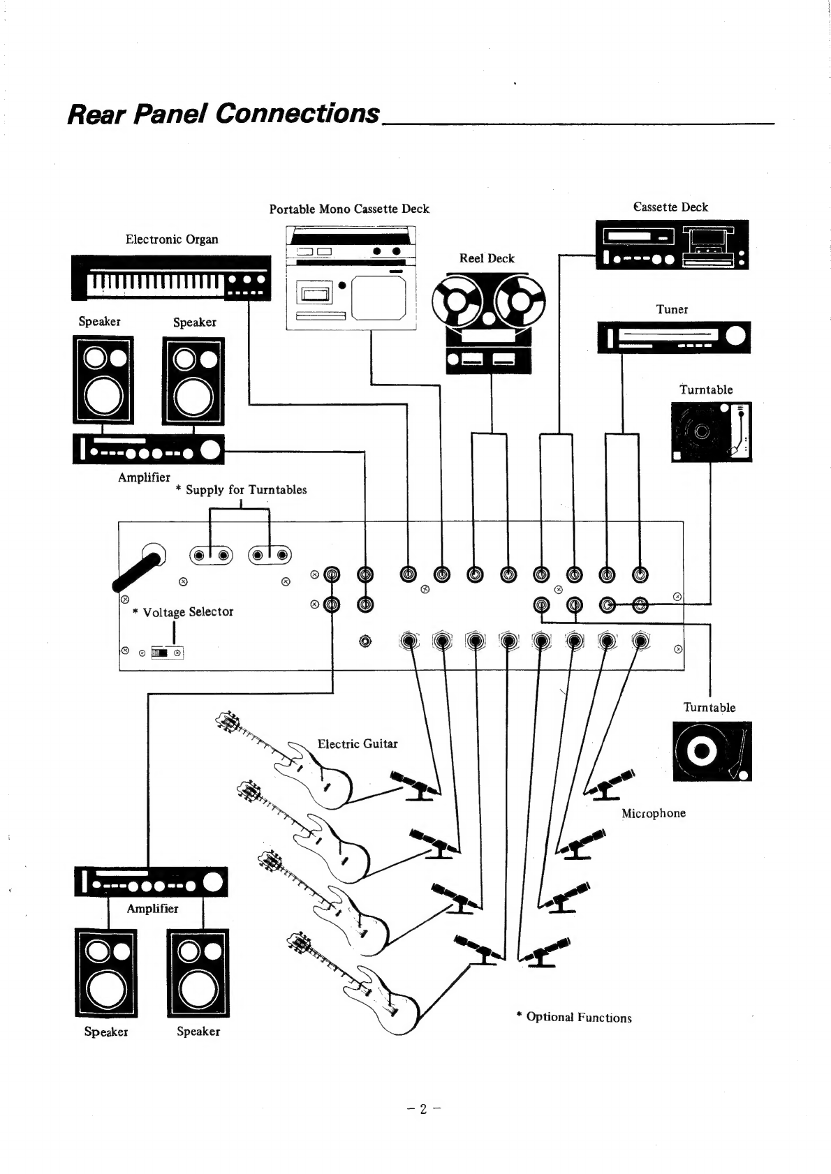
Rear
Panel
Connections
Portable
Mono
Cassette
Deck
Eassette
Deck
La
Electronic
Organ
le---ee
——_
Tuner
Amplifier
*
Supply
for
Turntables
Turntable
©
*
Voltage
Selector
©
©
is)
Turntable
Electric
Guitar
|
----e00--0
@
Amplifier
*
Optional
Functions
Speaker
Speaker

Rear
Panel
Connections
(continued)
1.
AC
INPUT
CORD
Plug
this
AC
INPUT
CORD
into
AC
outlet.
2.
AC
VOLTAGE
SELECTOR
(Optional)
In
case
of
multi
line
voltage
zone,
voltage
selector
(110V/220V)
is
provided.
For
the
single
power
source
area,
no
line
voltage
selector
is
provided
and
it
has
been
fixed
as
110
volts
or
220
volts
according
to
the
regional
requirement.
3.
AC
OUTLETS
FOR
TURNTABLES
(Optional)
You
can
turn
the
turntables
connected
to
this
outlets
on
and
off
by
using
the
switches
near
AC
main
switch.
4.
LINE
OUT
Signal
from
these
LINE
OUT
jacks
is
to
be
connected
to
AUX
jacks
or
TAPE
IN
jacks
if
necessary
on
the
amplifier.
5.
AUX
OUT
These
output
jacks
are
auxiliary
to
LINE
OUT
jacks
and
can
be
connected
with
auxiliary
amplifier.
6.
GND
TERMINAL
This
terminal
is
to
be
connected
to
the
ground
terminal
of
turntable
to
reduce
hum
to
minimum.
7.
LINE
INPUTS
These
input
jacks
are
to
be
connected
with
output
jacks
of
tuner,
cassette
deck
and
electronic
organ.
If
the
signals
are
stereophonic,
you
can
connect
left
and
right
channel
signals
with
independent
inputs
and
adjust
PANPOT
controls
to
the
left
and
right
ends.
8.
PHONO
INPUTS
Inputs
1
to
4
are
provided
to
be
connected
with
magnetic
cartridge
type
turntables.
9.
MIC
INPUTS
These
inputs
are
to
be
connected
with
microphones
and
electric
guitars.
You
can
attenuate
the
sensitivity
by
positioning
INPUT
SELECTOR
to
MIC
ATT.
:
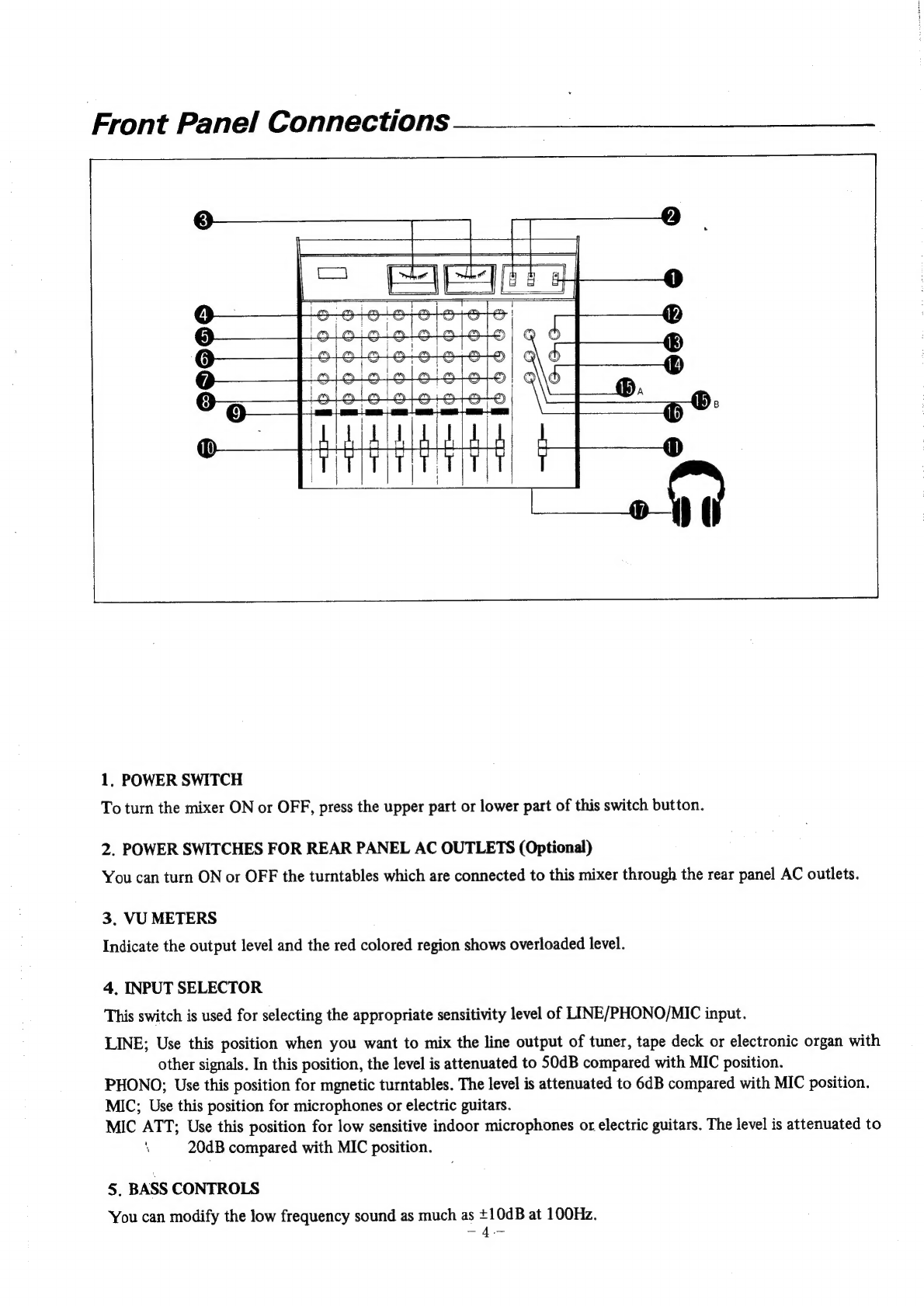
Front
Panel
Connections
1,
POWER
SWITCH
To
turn
the
mixer
ON
or
OFF,
press
the
upper
part
or
lower
part
of
this
switch
button.
2.
POWER
SWITCHES
FOR
REAR
PANEL
AC
OUTLETS
(Optional)
You
can
turn
ON
or
OFF
the
turntables
which
are
connected
to
this
mixer
through
the
rear
panel
AC
outlets.
3.
VU
METERS
Indicate
the
output
level
and
the
red
colored
region
shows
overloaded
level.
4,
INPUT
SELECTOR
This
switch
is
used
for
selecting
the
appropriate
sensitivity
level
of
LINE/PHONO/MIC
input.
LINE;
Use
this
position
when
you
want
to
mix
the
line
output
of
tuner,
tape
deck
or
electronic
organ
with
other
signals.
In
this
position,
the
level
is
attenuated
to
50dB
compared
with
MIC
position.
PHONO;
Use
this
position
for
mgnetic
turntables.
The
level
is
attenuated
to
6dB
compared
with
MIC
position.
MIC;
Use
this
position
for
microphones
or
electric
guitars.
MIC
ATT;
Use
this
position
for
low
sensitive
indoor
microphones
or
electric
guitars.
The
level
is
attenuated
to
‘
20dB
compared
with
MIC
position.
5.
BASS
CONTROLS
‘You
can
modify
the
low
frequency
sound
as
much
as
+10dB
at
100Hz.
-—4-
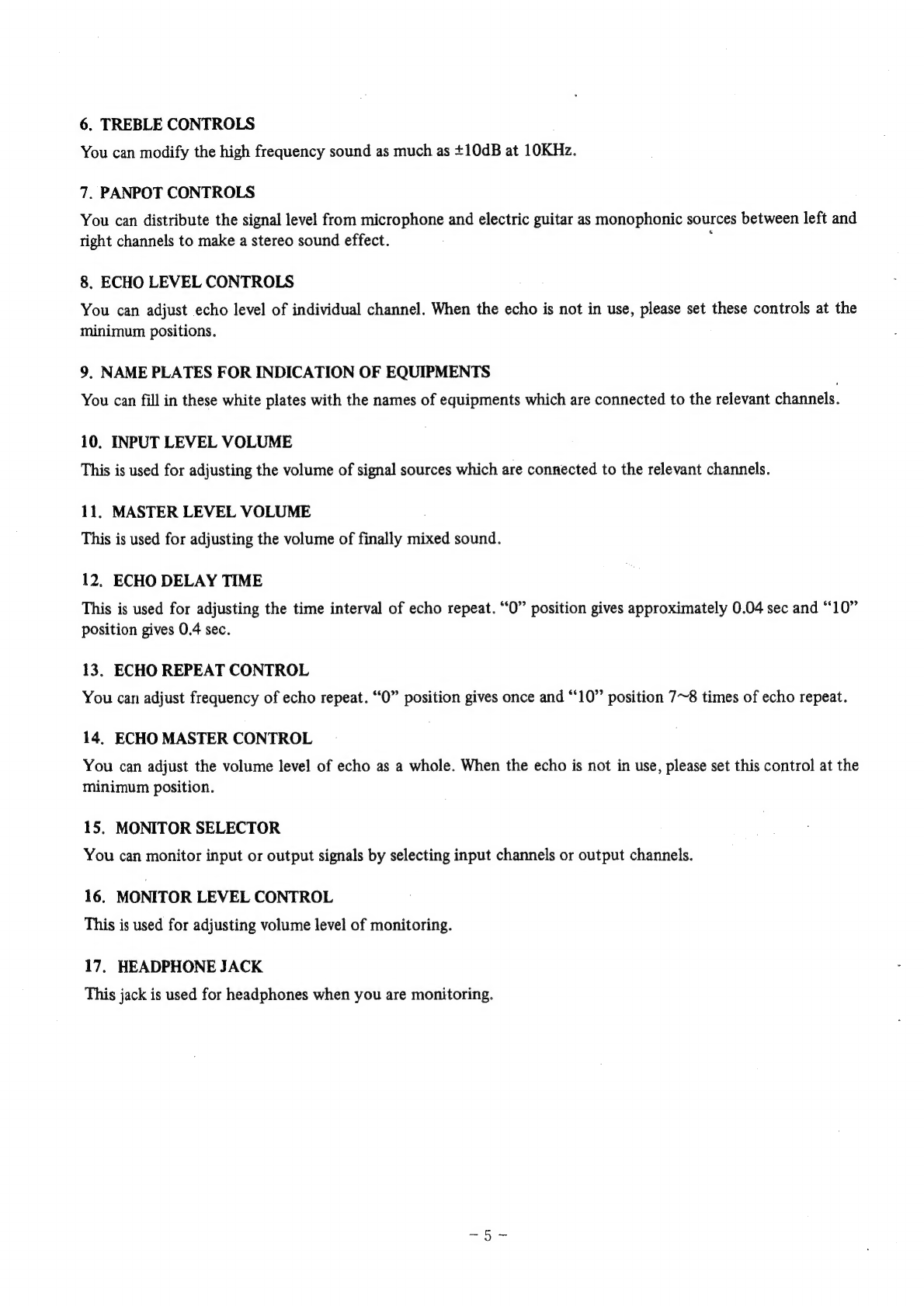
6.
TREBLE
CONTROLS
You
can
modify
the
high
frequency
sound
as
much
as
+10dB
at
10KHz.
7.
PANPOT
CONTROLS
You
can
distribute
the
signal
level
from
microphone
and
electric
guitar
as
monophonic
sources
between
left
and
right
channels
to
make
a
stereo
sound
effect.
;
8.
ECHO
LEVEL
CONTROLS
You
can
adjust
echo
level
of
individual
channel.
When
the
echo
is
not
in
use,
please
set
these
controls
at
the
minimum
positions.
9,
NAME
PLATES
FOR
INDICATION
OF
EQUIPMENTS
You
can
fill
in
these
white
plates
with
the
names
of
equipments
which
are
connected
to
the
relevant
channels.
10.
INPUT
LEVEL
VOLUME
This
is
used
for
adjusting
the
volume
of
signal
sources
which
are
connected
to
the
relevant
channels.
11.
MASTER
LEVEL
VOLUME
This
is
used
for
adjusting
the
volume
of
finally
mixed
sound.
12.
ECHO
DELAY
TIME
This
is
used
for
adjusting
the
time
interval
of
echo
repeat.
“0”
position
gives
approximately
0.04
sec
and
“10”
position
gives
0.4
sec.
13.
ECHO
REPEAT
CONTROL
You
can
adjust
frequency
of
echo
repeat.
“O”
position
gives
once
and
“10”
position
7~8
times
of
echo
repeat.
14,
ECHO
MASTER
CONTROL
You
can
adjust
the
volume
level
of
echo
as
a
whole.
When
the
echo
is
not
in
use,
please
set
this
control
at
the
minimum
position.
15.
MONITOR
SELECTOR
You
can
monitor
input
or
output
signals
by
selecting
input
channels
or
output
channels.
16.
MONITOR
LEVEL
CONTROL
This
is
used
for
adjusting
volume
level
of
monitoring.
17.
HEADPHONE
JACK
This
jack
is
used
for
headphones
when
you
are
monitoring.
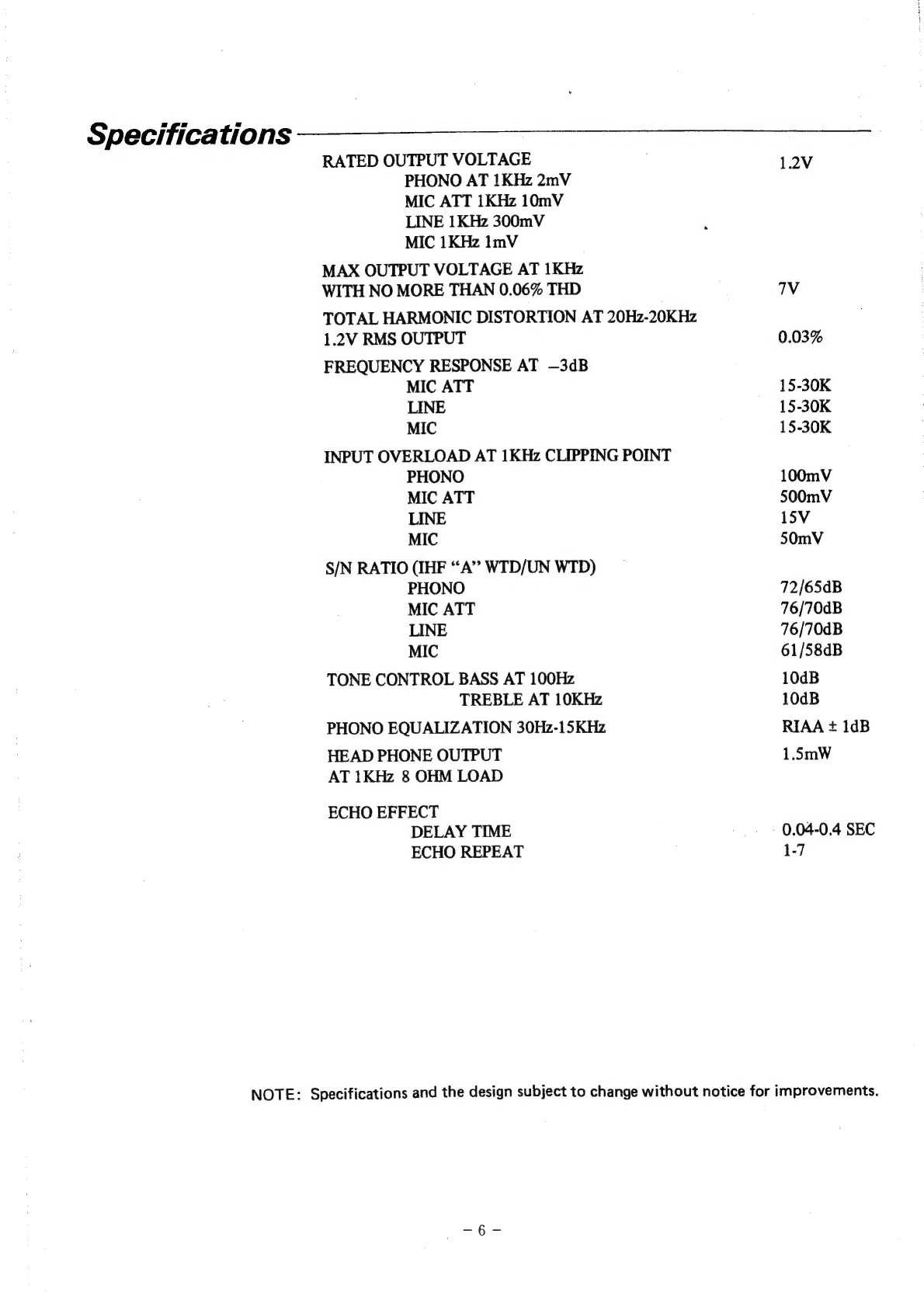
Specifications
RATED
OUTPUT
VOLTAGE
PHONO
AT
1KHz
2mV
MIC
ATT
1KHz
10mV
LINE
1KHz
300mV
MIC
1KHz
ImV
MAX
OUTPUT
VOLTAGE
AT
1KHz
WITH
NO
MORE
THAN
0.06%
THD
TOTAL
HARMONIC
DISTORTION
AT
20Hz-20KHz
1.2V
RMS
OUTPUT
FREQUENCY
RESPONSE
AT
—3dB
MIC
ATT
LINE
MIC
INPUT
OVERLOAD
AT
1KHz
CLIPPING
POINT
PHONO
MIC
ATT
LINE
MIC
S/N
RATIO
(IHF
“A”
WTD/UN
WTD)
PHONO
MIC
ATT
LINE
MIC
TONE
CONTROL
BASS
AT
100Hz
TREBLE
AT
10KHz
PHONO
EQUALIZATION
30Hz-15KHz
HEAD
PHONE
OUTPUT
AT
1KHz
8
OHM
LOAD
ECHO
EFFECT
DELAY
TIME
ECHO
REPEAT
1.2V
7V
0.03%
15-30K
15-30K
15-30K
100mV
500mV
15V
50mV
72/65dB
76/70dB
76/70dB
61/58dB
10dB
10dB
RIAA
+
1dB
1.5mW
-
0.04-0.4
SEC
1-7
NOTE:
Specifications
and
the
design
subject
to
change
without
notice
for
improvements.

xe)
(2)
oO
~S
je)
Oo
on
=
oO
Ww
=
©
D
oO
@
©
ESS
—
©
1]
ry
OoOe
CHANNEL
7
me
—
wie
att
po
time
CHANNEL
@
mic
maicsaTT
Ietol:
TATI36P
1C
102,
1¢
201,
1C301,1C
304:
Ny
435800
1302
:MN
3005
IC
303
/
MN
3108
02010301,
0401
:
MPS.9633
Q202
:
28K
30
0602
-MPSASS
403:
MPS
ACS
O50!
:
MOS
9401
MDS
945t
1015
Qbon
28c1819
0201,
0202
DB01,
D302,
D40!
(CDG24
er
MAISO
DS01,0502:wz140
D803
-
D307
:
IN
4002
NOTE!
1,
Resistonce
valves
ore
indicated
in
noms
wniess
otherwise
specif
leg
(%#1,000
,
#1,000,000
}
2.Copecivance
vetwes
ere
shown
in
etcrolereds
untess
otherwise
noted.
(Pe
micre
-
microtereds
)
‘S.Campenent
valves
ora
subject
1
without
oetieas.
4.A11
voltages
are
referanced
10
‘weund
under
the
following
S.Twe/\
mart
fount
on
some
ports
Indicates
the
Serene
of
the
ster
tecrer
ee
pert
Trerstere
onan
replacing,
be
sere
te
use
porte
of
isenticet
Gesignerion
.
V
‘4
(\})
Dd
Villy
@
OO?
WO
o30z
coeds
2
osor
ag
RUK
Cr0E.
.
2:
saat
nara
rigs
LIME
rl
bebe
ist
eit:
R29
PHONE
JACK
VAIOI:
IMPUT
FADER
VRIOZ:
GASS
CORTROL
VRIO3:
TREBLE
CONTROL
VRI04:
ECHO
VRIOS
A.B.
PAN
CONTROL
R201:
MASTER
FADER
VR302;ECHO
DELAY
TIME
VR
303.
6CHO
REPEAT
YR304:
ECHO
MASTER
presi
SWILIMPUT
SELECTOR
SwiTcH
SW2:MONITOR
SELECTOR
SWITCH
MAIN
SW3:MONITOR
SELECTOR
SWITCH
SUB
1n4002
FUSE
B'D
K-40304-2
F3504
0.854/230V
pRsov/0.54
A
o.c0amsovac/t\
VOLTAGE
SELECTOR
SWITCH
t%
OPTIONAL)
ACOV
SSmarz
VU
METER
RLUMINATE
Table of contents
Other Inkel Music Mixer manuals


