Inkel Juni JR20 MPE25K User manual

VzW MPE25K
Installation Manual
2008. 04
Draft Ver 0.5

2
Modified Manual LIST
Manual issue DATE Modified List Remark
Ver 0.2 2007. 08. 02 First Draft
Ver 0.3 2007. 09. 11
Added Information
▶ Changed DIP S/W control method
▶ Appendix C. System Block
▶ Appendix D. Troubleshooting for the MPE25K
Ver 0.4 2007. 10. 12. Modified Image
▶ Bias-T CU Port DC Block+50Ω Term
▶ Added material name of each image
Ver 0.5 2008. 04. 21 ▶ Changed Installation Bracket
▶ Updated System Block

3
▶Safety Precautions:
Î Use the power plug at the adaptor to turn the power on and off.
Î Please make sure that a ground wire is installed to connect the Antenna Unit to an appropriate
earth ground.
Î Refer servicing to a qualified technician who is familiar with NEC (National Electrical Code) and
a related regulation for installation to reduce the risk of electrical damage when the unit does not
appear to operate normally or exhibits a marked change in performance.
Radio Regulation Conformance
This equipment has been tested and found to comply with the limits for a Class B digital device,
pursuant to Part 15 of the FCC Rules. These limits are designed to provide reasonable protection
against harmful interference in a residential installation. This equipment generates, uses and can
radiate radio frequency energy and, if not installed and used in accordance with instructions, may
cause harmful and, if not installed and used in accordance with instructions, may cause harmful
interference to radio communications. However, there is no guarantee that the interference will not
occur in a particular installation.
This device complies with Part 15 of the FCC rules. Operation is subject to the following two
conditions: (1) this device may not cause harmful interference. And (2) this device must accept any
interference received, including interference that may cause understand operation.
FCC RF Radiation Exposure Statement
The antenna(s) used for this transmitter must be installed to provide a
separation distance of at least 20 cm from all persons and must not be co-located or
operating in conjunction with any other antenna or transmitter.
WARNING
Any changes or modifications not expressly approved by the manufacturer could void
the user’s authority to operate the equipment.

4
<Table of Contents>
1. Installation Flow Chart...................................................................................................... 7
2. Component Verification and Explanation.............................................................................8
2.1 DONOR UNIT(DU)....................................................................................................9
2.2 COVERAGE UNIT(CU)............................................................................................. 10
3. Preparing for DU and CU Installation........................ 오류! 책갈피가 정의되어 있지 않습니다.
4. BAND SETTING ...........................................................오류! 책갈피가 정의되어 있지 않습니다.
5. DONOR UNIT(DU) SET Installation ................................................................................... 15
5.1 BRACKET-DU Image.............................................................................................. 15
5.1.1. DU 에 BRACKET –DU Connection Image ........................................................ 15
5.1.2. BRACKET-DU Connection to Installation Place(WALL or POLE) Image................. 15
5.2 BRACKET Connection to DU................................................................................... 16
5.3 BRACKET Connection depending on Installation Place................................................ 17
5.3.1. BRACKET/MTG POLE MOUNTING................................................................... 17
5.3.2. BRACKET/MTG LUMBER WALL Mounting......................................................... 17
5.3.3. BRACKET/MTG CONCRETE WALL Mounting .................................................... 18
5.4 Connection DU(same as 5.1) with BRACKET(same as 5.2).......................................... 18
5.5 Installation Completion. .......................................................................................... 20
6. CU Wall & Ceil Mount Installation..................................................................................... 21
6.1. MTG Bracket Image............................................................................................... 21
6.2 GYPSUM BOARD WALL MOUNTING.......................................................................... 22
6.3 CONCRETE WALL MOUNTING ................................................................................. 22
6.4 LUMBER WALL MOUNTING ..................................................................................... 23
6.5 Install Bracket Connection with CU........................................................................... 24
6.6 CU SET Installation Completion................................................................................ 24
7. Power Connection and Optimization SETTING ................오류! 책갈피가 정의되어 있지 않습니다.
8. Status Check ................................................................................................................ 30
8.1 DU FAULT LED...................................................................................................... 30
8.2 CU FAULT LED...................................................................................................... 30
Appendix A. Product Introduction........................................................................................ 32
A.1 Overview .............................................................................................................. 32
A.2 Supported Frequency Range................................................................................... 34
Appendix B. System Specifications...................................................................................... 35
Appendix C. System Block.................................................................................................. 36
Appendix D. Troubleshooting for MPE25K............................................................................. 37

5
<Figures>
Fig. 1 Installation Flow Chart....................................................................................................................................7
Fig. 2 List of all the Componants in the System................................... 오류! 책갈피가 정의되어 있지 않습니다.
Fig. 3Additional CU Componants......................................................... 오류! 책갈피가 정의되어 있지 않습니다.
Fig. 4 DONOR UNIT(DU) Image..........................................................오류! 책갈피가 정의되어 있지 않습니다.
Fig. 5 CU Image....................................................................................... 오류! 책갈피가 정의되어 있지 않습니다.
Fig. 6 DIPS/W Basic Setting................................................................. 오류! 책갈피가 정의되어 있지 않습니다.
Fig. 7 MTG Bracket Image.......................................................................................................................................15
Fig. 8 MTG BRACKET Mounting (Pole, LumberWall, Concrete Wall) Connection Image.............................15
Fig. 9 DU Bracket Connection Diagram.................................................................................................................16
Fig. 10 POLE MOUNTING MTG BRACKET-DU Connection Sequence...........................................................17
Fig. 11 LUMBER WALL MOUNTING MTG BRACKET-DU Connection Sequence........................................17
Fig. 12 CONCRETE WALLMOUNTING MTG BRACKET-DU Connection Sequence...................................18
Fig. 13 DU Unit Wall Mounting...............................................................................................................................19
Fig. 14 DU Unit POLE Mounting Installation Completion Diagram...................................................................20
Fig. 15 DU Unit LUMBER WALL Mounting Installation Completion Diagram................................................20
Fig. 16 DU Unit CONCRETE WALLMounting Installation Completion Diagram...........................................20
Fig. 17 CU MTG Bracket Image & Hole distance..................................................................................................21
Fig. 18 CU Bracket Gypsum Wall Mounting..........................................................................................................22
Fig. 19 CU Bracket Concrete Wall Mounting.........................................................................................................23
Fig. 20 CU Bracket Lumber Wall Mounting ..........................................................................................................23
Fig. 21 CU MTG Bracket – CU SET Connection Image .......................................................................................24
Fig. 22 CU Installation Sequence.............................................................................................................................24
Fig. 23 Power PORT Connection Digram...............................................................................................................25
Fig. 24 POWER INJECTOR Installation Diagram...............................................................................................26
Fig. 25 DU ANT Tilt Diagram..................................................................................................................................28
Fig. 26 Verifying reception Status Diagram...........................................................................................................29
Fig. 27 DIPS/W Diagram.........................................................................................................................................29
Fig. 28 DU LED Diagram.........................................................................................................................................30
Fig. 29 CU LED Diagram.........................................................................................................................................31
Fig. 30 System Installation Diagram .......................................................................................................................32
Fig. 31 Basic Connection Diagram...........................................................................................................................33

6
<Tables>
Table 1 Band Setting.................................................................................................................................................14
Table 2 Cellular Frequency......................................................................................................................................34
Table 3 PCS Frequency.............................................................................................................................................34
Table 4 RF Specifications..........................................................................................................................................35
Table 5 Physical Specifications.................................................................................................................................35
Table 6 Antenna Specifications................................................................................................................................35

7
1. Installation Flow Chart
This document will provide details on how to successfully install the Juni JR-20 Repeater
system. The flow chart below provides a step by step guide for installing the JR-20 Repeater
Fig. 1 Installation Flow Chart
1. Start
3. Locating
4. Band Setting
5. DU
6. CU
7. Power / Optimization
9. End
8. Status Check
2. Package Check
8
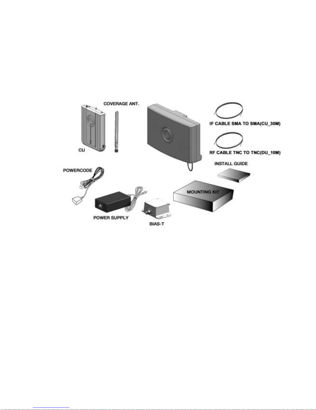
2. Component Verification and Explanation
The first step when installing the repeater is to check that all components are present and that the
parts do not have any visible faults. The figure below illustrates the items included in the Juni JR-
20 Repeater Kit.
Fig. 2 List of all the Components in the System
9
Fig. 3 Additional Coverage Unit Components
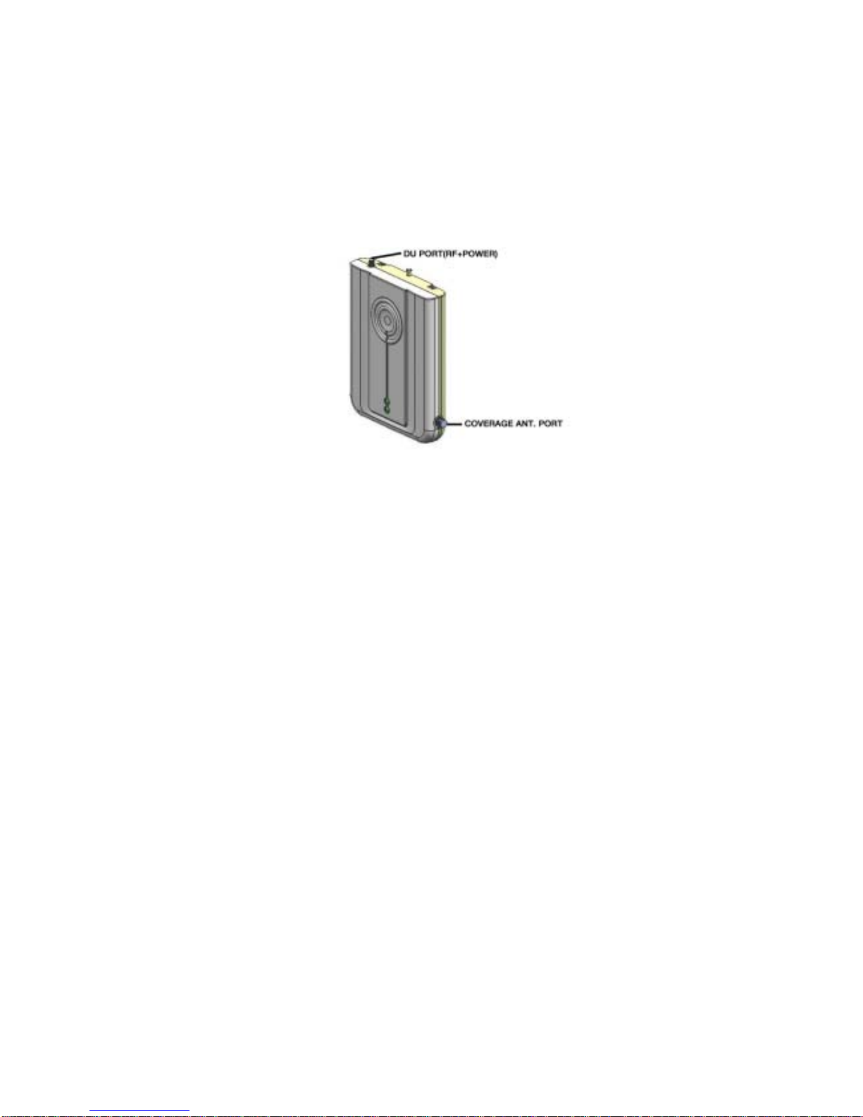
2.1 DONOR UNIT(DU)
The role of the Donor Unit is to communicate with the BTS. It is located outside the building
where service is to be improved. The Donor Unit can be mounted onto a wall or a pole,
depending on the specific installation needs.
Fig. 4 DONOR UNIT(DU)
10
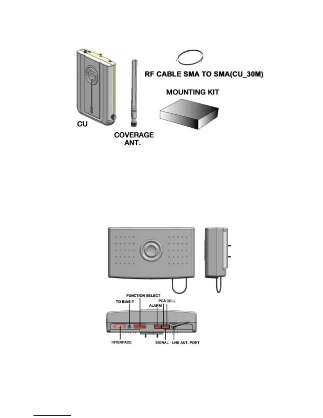
2.2 COVERAGE UNIT(CU)
The role of the Coverage Unit is to communicate with the mobiles within the building which
needs improved coverage. It is intended for wall mounting.
Fig. 5 Coverage Unit (CU)
3. Preparing for Donor Unit and Coverage Unit Installation
Determining the proper installation location for the Donor and Coverage Units is very important,
since their position will determine the overall performance of the repeater.
The authorized installer should determine where it will be mounted in accordance with the
instructions received by Juni for best reception by the BTS.
When determining the position of the Donor Unit, the following points should be considered.
ÎWhere is the target Donor BTS?
ÎWill the Donor Unit be mounted on a wall or a pole? (99% will be wall mounted)
ÎTry to avoid areas where may possibly hinder the communication between the Donor Unit
and the BTS such as large walls.
ÎThe Donor Unit should not be located any more than 10 feet away from the wall penetration
or window which will allow access to the inside of the building.
When determining the position of the Coverage Unit, the following points should be considered.
ÎTry to position the Coverage Unit at the center of the desired indoor coverage area.
ÎTry to position the Coverage Unit so that it is clearly visible throughout the desired indoor
coverage area.
ÎMake sure that the distance from the Coverage Unit to the power source is less than 20 feet.
11
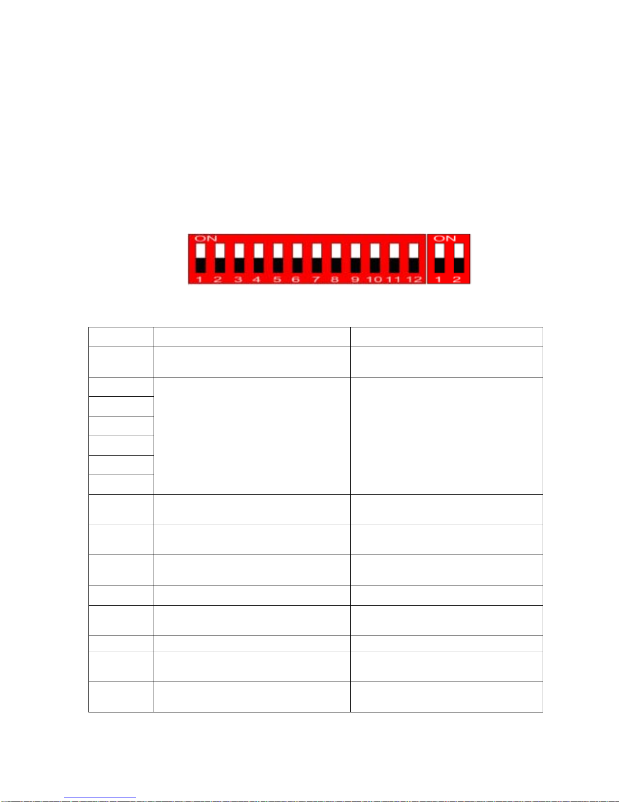
4. BAND SETTING
Once the planning of the location and positioning of the Donor and Coverage Units is finalized,
the authorized installer should proceed with installing the Donor and Coverage Units. But first,
the installer should set the appropriate frequency band(s) for the repeater. The figure and table
below show the DIP Switch and the functions for each section. Usually both the PCS and
Cellular bands have to be set up.
After DIP S/W setting, turn power ON/OFF or DIP S/W 12# PIN ON/OFF.
ÎDIP Switch Functions
Fig. 6 DIP Switch General Settings
PIN NO. FUNC TION STATUS
1 Cellular Band Selection ON : Cellular B Band
OFF : Cellular A Band
2
3
4
5
6
7
PCS Band Selection See the next tables below
8 PCS EVDO OFFSET ON : PCS Gain OFFSET 3dB(increase) ON
OFF : PCS Gain OFFSET 3dB(reduction) OFF
9 Cellular EVDO OFFSET
ON : Cellular Gain OFFSET 3dB(increase )ON
OFF : Cellular Gain OFFSET 3dB(reduction) OFF
10 Band Selection Mode ON : Software Band Selection Mode
OFF : Hardware Band Selection Mode
11 Uplink RF OFF ON : Reverse RF Power OFF
OFF : Reverse RF Power ON
12 Hardware Reset ON : Reset
OFF : Normal Operation
PIN NO. FUNC TION STATUS
1 PCS PATH HARDWARE ON/OFF ON : PCS UL/DL PATH HARDWARE ON
OFF : PCS UL/DL PATH HARDWARE OFF
2 CELLULAR PATH HARDWARE ON/OFF ON : CELLULAR UL/DL PATH HARDWARE ON
OFF : CELLULAR UL/DL PATH HARDWARE OFF
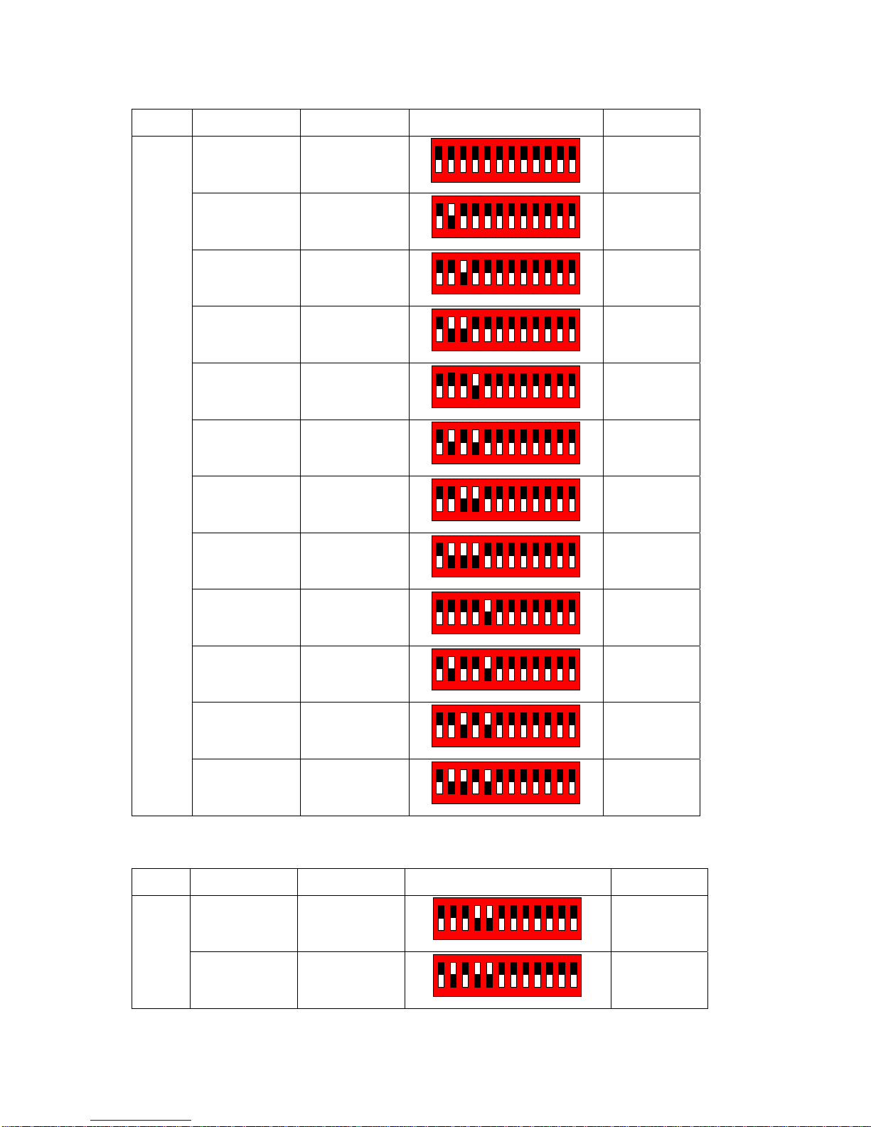
12
BW UP LINK DOWN LINK DIP SWITCH REMARK
1850 ~ 1855 1930 ~ 1935
123456789101112
ON
White color
is switch.
1855 ~ 1860 1935 ~ 1940
123456789101112
ON
1860 ~ 1865 1940 ~ 1945
123456789101112
ON
1865 ~ 1870 1945 ~ 1950
123456789101112
ON
1870 ~ 1875 1950 ~ 1955
123456789101112
ON
1875 ~ 1880 1955 ~ 1960
123456789101112
ON
1880 ~ 1885 1960 ~ 1965
123456789101112
ON
1885 ~ 1890 1965 ~ 1970
123456789101112
ON
1890 ~ 1895 1970 ~1975
123456789101112
ON
1895 ~ 1900 1975 ~ 1980
123456789101112
ON
1900 ~ 1905 1980 ~ 1985
123456789101112
ON
5MHz
1905 ~ 1910 1985 ~ 1990
123456789101112
ON
BW UP LINK DOWN LINK DIP SWITCH REMARK
1850 ~ 1860 1930 ~ 1940
123456789101112
ON
10MHz
1855 ~ 1865 1935 ~ 1945
123456789101112
ON

13
1860 ~ 1870 1940 ~ 1950
123456789101112
ON
1865 ~ 1875 1945 ~ 1955
123456789101112
ON
1870 ~ 1880 1950 ~ 1960
1 2 3 4 5 6 7 8 9 10 11 12
ON
1875 ~ 1885 1955 ~ 1965
1 2 3 4 5 6 7 8 9 10 11 12
ON
1880 ~ 1890 1960 ~ 1970
1 2 3 4 5 6 7 8 9 10 11 12
ON
1885 ~ 1895 1965 ~ 1975
1 2 3 4 5 6 7 8 9 10 11 12
ON
1890 ~ 1900 1970 ~ 1980
1 2 3 4 5 6 7 8 9 10 11 12
ON
1895 ~ 1905 1975 ~ 1985
1 2 3 4 5 6 7 8 9 10 11 12
ON
1900 ~ 1910 1980 ~ 1990 123456789101112
ON
BW UP LINK DOWN LINK DIP SWITCH REMARK
1850 ~ 1865 1930 ~ 1945 123456789101112
ON
1855 ~ 1870 1935 ~ 1950
123456789101112
ON
1860 ~ 1875 1940 ~ 1955
123456789101112
ON
1865 ~ 1880 1945 ~ 1960 123456789101112
ON
1870 ~ 1885 1950 ~ 1965
123456789101112
ON
15MHz
1875 ~ 1890 1955 ~ 1970
123456789101112
ON

14
1880 ~ 1895 1960 ~ 1975
123456789101112
ON
1885 ~ 1900 1965 ~ 1980
123456789101112
ON
1890 ~ 1905 1970 ~ 1985
123456789101112
ON
1895 ~ 1910 1975 ~ 1990
123456789101112
ON
Table 1 Band Setting

15
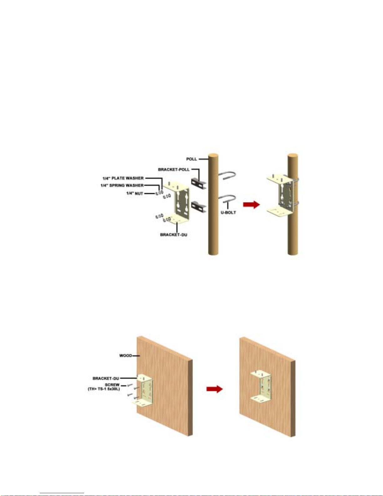
5. DONOR UNIT(DU) SET Installation
5.1 BRACKET-DU Image
5.1.1. DU 에 BRACKET –DU Connection Image
1) The length unit is [mm].
Fig. 7 MTG Bracket Image
5.1.2. BRACKET-DU Connection Image to Installation(WALL or POLE)
( Pole Mounting ) ( Lumber Wall Mounting) ( Concrete Wall Mounting )
Fig. 8 MTG BRACKET Mounting (Pole, Lumber Wall, Concrete Wall) Connection Image

16
5.2 BRACKET Connection to DU
1) 1) APPLY NUT, SPRING WASHER, PLATE WASHER.
(Do not Connect Completely)
[NUT, SPRING WASHER, PLATE WASHER each 4ea]
2) Apply BRACKET/MTG to DU. APPLY NUT COMPLETELY USING PROVIDED TOOL.
[BRACKER/MTG 1ea]
Fig. 9 DU Bracket Connection Diagram
17
5.3 BRACKET Connection depending on Installation Place
5.3.1. BRACKET/MTG POLE MOUNTING
1) Secure DU to the pole using U-BOLT.
2) Insert U-BOLT to between BRACKET-POLE and BRACKET-DU
3) Apply the pole to the BRACKET-DU: use the nuts and u-bolts provided to fixate the
bracket into the Pole.
[BRACKET-DU 1ea, BRACKET-POLE 2ea, U-Bolt 2ea, NUT, SPRING WASHER, PLATE
WASHER each 4ea]
Fig. 10 POLE MOUNTING MTG BRACKET-DU Connection Sequence
5.3.2. BRACKET/MTG LUMBER WALL Mounting
1) Secure BRACKET-DU to the wooden wall. Using cross driver connect SCREW to wooden
wall through BRACKET-DU.
[BRACKET-DU 1ea, SCREW 4ea]
Fig. 11 LUMBER WALL MOUNTING MTG BRACKET-DU Connection Sequence

18
5.3.3. BRACKET/MTG CONCRETE WALL Mounting
1) Drill on the wall as the BRACKET-ANT distance. (forφ 10mm Hole depth to be 30 to 40
mm.)
2) INSERT SET-ANCHOR TO DRILLED HOLE.
3) Secure BRACKET-DU to the Wall and fix the nut.
[BRACKER-DU 1ea, SET-ANCHOR 4ea]
Fig. 12 CONCRETE WALL MOUNTING MTG BRACKET-DU Connection Sequence
5.4 DU Connection (same as 5.1) with BRACKET(same as 5.2)
1) APPLY DU to the BRACKET.
2) Apply the NUT to the upside of BRACKET like below sequence. –Do not apply the NUT
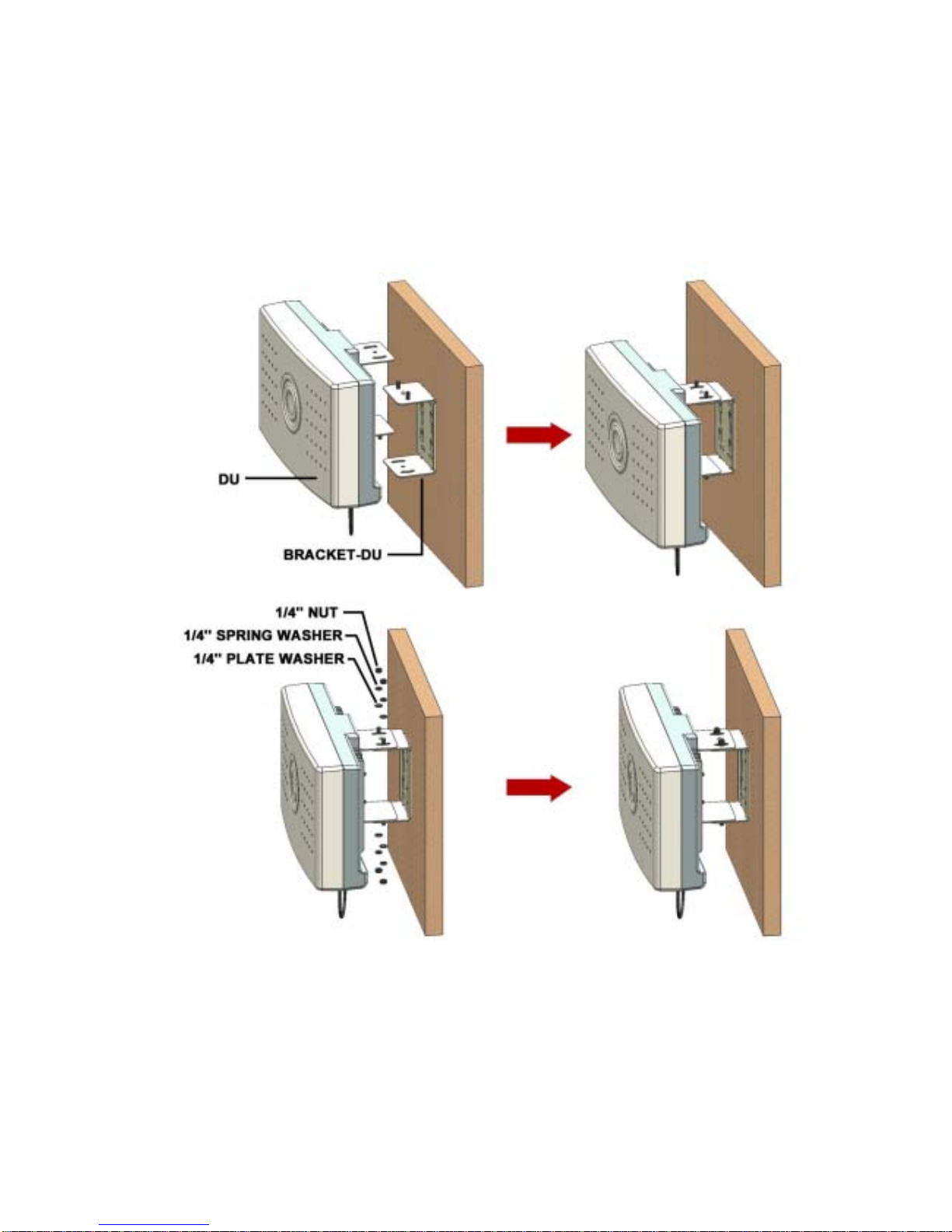
19
completely.
3) Set the receiving direction of the ANTENNA and apply the NUT completely using the
provided tool.
[NUT, SPRING WASHER, PLATE WASHER each 4ea]
Fig. 13 DU Unit Wall Mounting

20
5.5 Installation Completion.
Fig. 14 DU Unit POLE Mounting Installation Completion Diagram
Fig. 15 DU Unit LUMBER WALL Mounting Installation Completion Diagram
Fig. 16 DU Unit CONCRETE WALL Mounting Installation Completion Diagram
Table of contents


