Inkema RH11 User manual

Inkema
Loading Bays • Dock Shelters • High-Speed Doors
Fire Doors • Free Standing Frames and Dock Houses • Scissor Lifts
Loading Bridges • Industrial Doors
Instructions manual
Hydraulic dock leveller
Models: RH11 and RH12
EMBEDDED AND SELF-SUPPORTING
RH11
RH12
Contents

Instructions manual RH11 and RH12 Inkema
V03 –2016
www.inkema.com
2
01 –Introduction........................................................................................................................................ 3
02 –Technical specifications................................................................................................................... 4
02.01 –Usage conditions and limits .................................................................................................................4
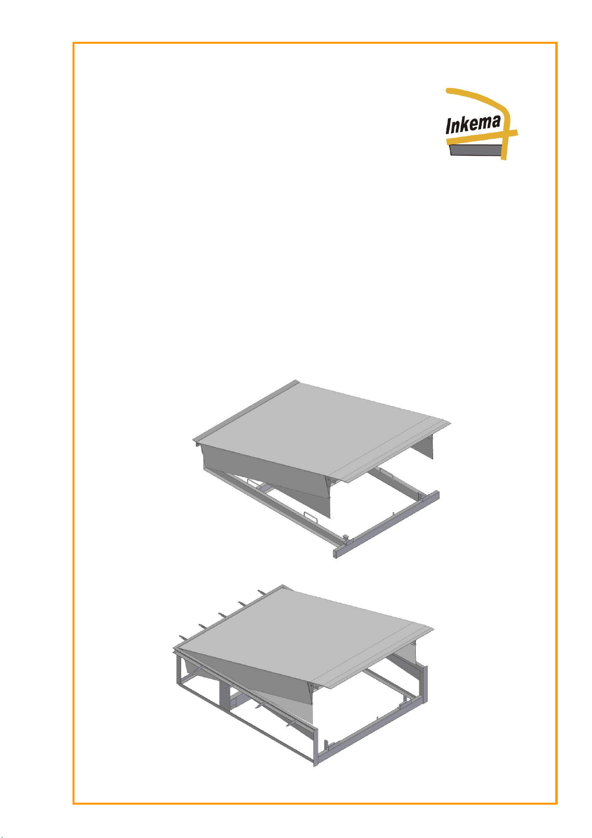
02.02 –RH11 embedded pit.............................................................................................................................4
02.03 –RH12 self-supporting pit ...................................................................................................................... 5
02.04 –Platform ...............................................................................................................................................5
02.05 –Lip........................................................................................................................................................5
02.06 –Bedplate...............................................................................................................................................5
02.07 –Hydraulic power unit ............................................................................................................................6
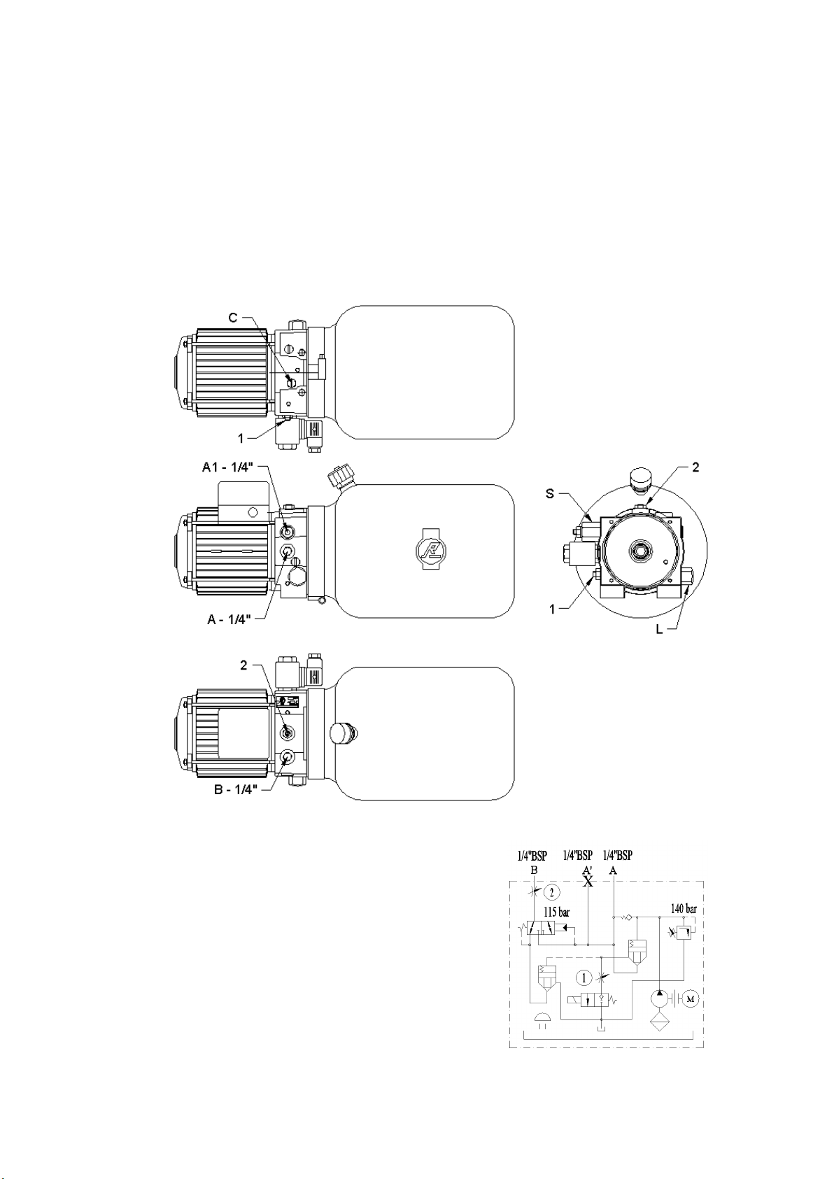
02.07.01 –Hydraulic unit version 03..................................................................................................6
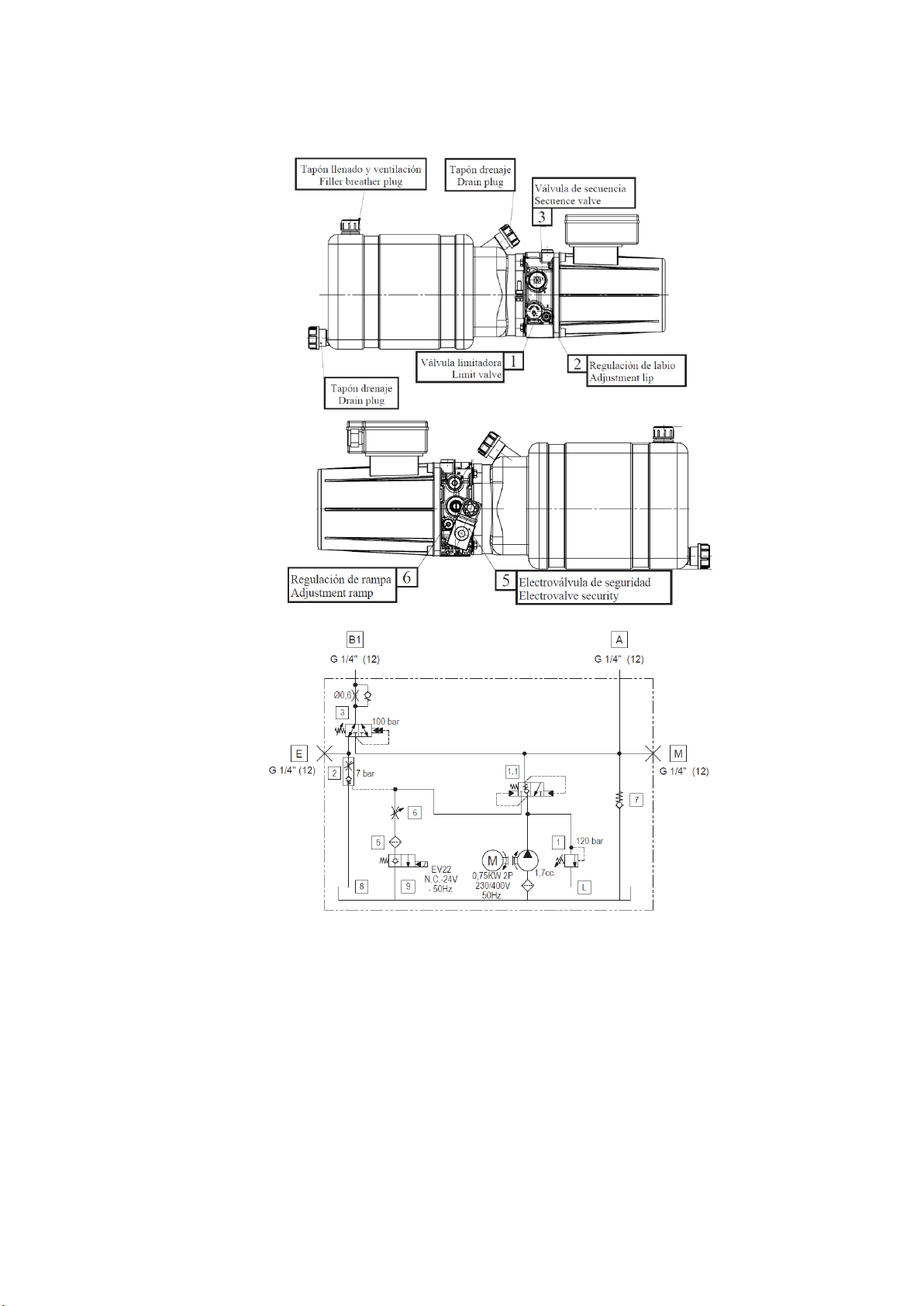
02.07.02 –Hydraulic unit version 07..................................................................................................7
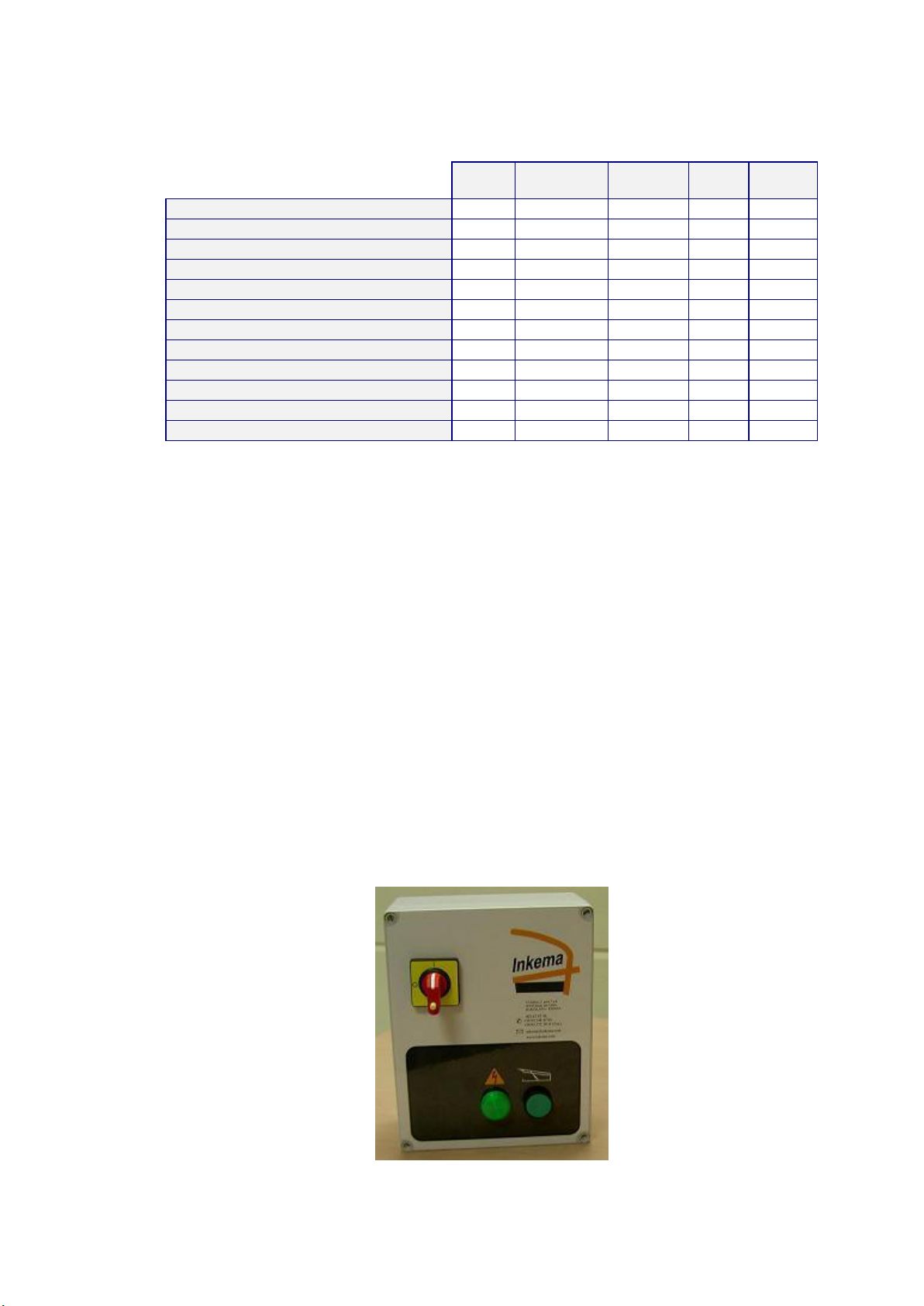
02.08 –Electrical control panel.........................................................................................................................7
02.09 –Safety systems .................................................................................................................................... 7
02.10 –Maintenance........................................................................................................................................ 8
02.10.01 –Hydraulic oil ..................................................................................................................... 8
02.10.02 –Grease points................................................................................................................... 8
02.10.03 –Dock leveller descent speed regulation............................................................................ 8
02.10.04 –Lip opening speed............................................................................................................8
02.10.05 –Maintenance plan.............................................................................................................9
02.11 –Instructions for use............................................................................................................................... 9
02.11.01 –Before use........................................................................................................................ 9
02.11.02 –During use...................................................................................................................... 10
02.11.03 –After use......................................................................................................................... 10
02.11.04 –Precautions during use .................................................................................................. 10
03 –CE Declaration................................................................................................................................. 11
04 –Machine units and parts ................................................................................................................. 12
05 –Installation........................................................................................................................................ 14
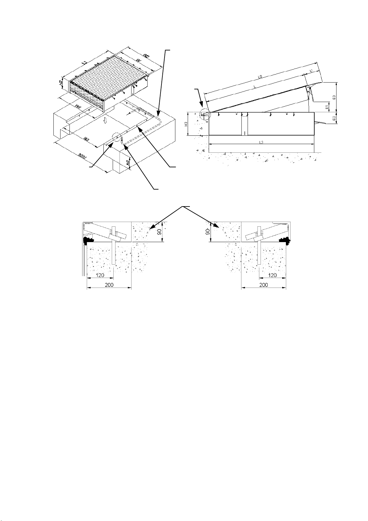
05.01 –Positioning in the pit........................................................................................................................... 14
05.02 –Securing the leveller in the pit............................................................................................................ 14
05.02.01 –Securing in the case of an embedded model................................................................. 14
05.02.02 –Securing in the case of a self-supporting model............................................................. 15
05.03 –Installing the electrical control panel.................................................................................................. 16
05.04 –Completed installation........................................................................................................................ 16
05.05 –Electrical control panel connection..................................................................................................... 17
05.05.01 –Connecting the power input ........................................................................................... 17
05.05.02 –Motor input connection................................................................................................... 17
05.05.03 –Electro valves connection .............................................................................................. 17
05.05.04 –Description of the connection terminals ......................................................................... 18
05.05.05 –Actions Selection............................................................................................................ 19
05.05.06 –Timers............................................................................................................................ 19
05.05.07 –Operation....................................................................................................................... 19
05.05.08 –Accessories.................................................................................................................... 19
05.05.09 –Characteristics ............................................................................................................... 19
06 –Dismantling...................................................................................................................................... 20
06.01 –Dismantling an embedded leveller..................................................................................................... 20
06.02 –Dismantling a self-supporting leveller ................................................................................................ 20
07 –Incidents........................................................................................................................................... 22
07.01 –The panel DOES NOT light up........................................................................................................... 22
07.02 –The ramp DOES NOT rise................................................................................................................. 23
07.03 –The leveller DOES NOT descend...................................................................................................... 24
07.04 –The lip DOES NOT open or functions very slowly ............................................................................. 24
07.05 –The lip opens before the leveller is raised.......................................................................................... 24
08 –Contact............................................................................................................................................. 25

Instructions manual RH11 and RH12 Inkema
V03 –2016
www.inkema.com
3
01 –Introduction
This manual is a guide for the correct, safe installation, use and maintenance of the RH11 and RH12 dock
levellers.
Compliance with the instruction set forth herein ensures the long life of the machine and respect for the safety
guidelines prevents the most common work or maintenance-related accidents.
The instructions in this manual do not, in themselves, guarantee safe working and do not release operators from
their obligation to observe the safety code, legislation or local or national regulations.
The service rule set out in this manual is only valid for mobile ramps and for loading and unloading trucks.
In the event of mislaying the instructions and maintenance manual, another copy that is specific for the machine
should be requested. It is essential and absolutely necessary to keep this manual with the machine, in order to
consult it at any time, or settle any doubts regarding its use.
The manufacturer has no direct control over the operations, locations or maintenance of the machine. Operators are
responsible for using best safety and maintenance practices.
Operators have the obligation to read and make sure they understand this manual before they use the machine.
Using the machine with caution and adequate training not only protects the operator but also the people who
depend on his work.
The information set out in the manual is valid at the time of publication.
The photographs and drawings are generic; as a result, this information may be changed, due to the constant
development and research carried out by INKEMA.
In the event of discrepancy, please consult the technical department.
The manual is an inseparable part of the machine and must be kept with it in the event of sale.

Instructions manual RH11 and RH12 Inkema
V03 –2016
www.inkema.com
4
02 –Technical specifications
Ramp designed pursuant to the UNE-EN 1398 standard
Calculated for a maximum nominal load of: (See its plate characteristics)
02.01 –Usage conditions and limits
Nominal load capacity 6t
Motor electrical voltage 230/400 volt. 3F 50Hz
Motor electrical power 0.75 Kw.
Electrical output voltage to emergency electro valve 24 volt. AC.
Max. operating pressure of the hydraulic circuit 140 kg/cm² (Bar)
Operating temperature range (-10ºC +40ºC)
Noise level generated <70db
Max. transit speed 10Km/h
Max. operating gradient 12.5% (7º)
Do not work with the machine while the emergency stop is activated or if the power supply has been cut off.
02.02 –RH11 embedded pit
(*) Pit tolerance
Detail A of subframe
Note: Metal profile joints with continuous cord and a neck of 6mm
Floor of at least H250 concrete with a thickness greater than or equal to 200mm
PIT FRAME
01
02
03
04
2 un.
2 un.
(1+1) Un. **
15 un. **
LPN-80.8 x (L3 – 10)
LPN-80.8 x (W3 + 160)
LPN-80.8 x H3
#3x40x200
(**) Parts with some type of machining (Ask the Technical Department for drawings)
The diagonals of the pit must be equal ± 5 mm
Detail A
Recess tube Ø50mm. for electrical conductors as far as
the electrical panel.
Allow for a cable guide inside the tube.
Position electrical cables 500 mm from the door opening
01- LPN-80.8
Weld on forged
04 - Claw
Obra civil (Ver nota)

Instructions manual RH11 and RH12 Inkema
V03 –2016
www.inkema.com
5
02.03 –RH12 self-supporting pit
Detail A Detail B
Note: Metal profile joints with continuous cord and a neck of 6mm
Floor of at least H250 concrete with a thickness greater than or equal to 200mm.
02.04 –Platform
Superior tear plate (thickness 6/8mm.), quality ST-37.
10 cold rolled profiles
2 cold rolled lateral profiles (non-shear safety panels).
Front hinge unit (lip joint).
Rear hinge unit (platform joint).
Safety bar for executing maintenance work.
02.05 –Lip
Tear plate (thickness 13/15mm.), quality ST-37.
Press stroke 5º 150mm. from the end (for perfect adjustment to the truck).
Milled at the end (to ease the passage of the fork-lift trucks).
02.06 –Bedplate
Rear assembly (head) formed by rolled profiles.
Front assembly with profiles for supporting the lip.
Side profiles joining the front assembly with the rear assembly.
The movements of the platform and lip are executed through an electro hydraulic unit.
Recess tube Ø50mm. for electrical conductors as far as
the electrical panel.
Allow for guide cable inside the tube.
Detail A
Position electric cable 500 mm from the door opening
Corrugated steel notches Ø20 embedded in concrete and
laid out on either side.
Detail B
Civil engineering (See note)

Instructions manual RH11 and RH12 Inkema
V03 –2016
www.inkema.com
6
02.07 –Hydraulic power unit
1.0CV electric motor. 0’75kw 230/400Volt 3F 50Hz.
Hydraulic pump with flowrate of 5 litres/minute.
7-litre tank with oil level viewer.
Logicblock where all the elements are incorporated (including 24V electro valve).
Ø50mm. cylinder with rod for raising platform and parachute safety valve.
1 Ø30mm. cylinder with rod for lip raising.
Leads, connection fittings, etc…
The machine may be supplied with any of the following hydraulic unit versions, both are identical and perform the
same function.
02.07.01 –Hydraulic unit version 03
1
Leveller regulation
2
Lip regulation
A
Lift cylinder
A1
Lift cylinder
B
Lip cylinder
C
Screw and spring
L
Limit valve
S
Sequence valve

Instructions manual RH11 and RH12 Inkema
V03 –2016
www.inkema.com
7
02.07.02 –Hydraulic unit version 07
02.08 –Electrical control panel
(See electrical control panel connections, page 17)
Transformer for manoeuvring circuit at 24Volt. AC.
Green light indicating ON.
Emergency stop/section switch.
Thermal switch.
Fuses.
Terminal block.
Box 190X*240Y*105Z (IP-55)
02.09 –Safety systems
Emergency and/or power failure electro valve
Emergency stop/section switch.
Elevation cylinder safety valve
Toe guards

Instructions manual RH11 and RH12 Inkema
V03 –2016
www.inkema.com
8
Non-slip surface
02.10 –Maintenance
The correct operation and long life of the ramp depend largely on the preventive maintenance work carried out.
Advanced maintenance may only be carried out by the INKEMA technical service or staff authorised by the latter.
This maintenance is carried out to ensure that the product conserves the safety and usage characteristics it had when
it was first installed.
All changes, repairs or manipulation of the product that fail to comply with these regulations will lead to the
cancellation of the one-year warranty term and the liability of INKEMA for the product will automatically end.
Continuous greasing, painting and vigilance is the best way to guarantee its performance for many years.
02.10.01 –Hydraulic oil
The hydraulic oil must be replaced every two years.
The oil must contain agents that prevent the formation of foam, oxidation and water absorption. If the winter
temperatures are very low, the oil must not be too thick and its viscosity index must remain stable at low
temperatures.
Never mix different oils, as the new oil may have a different resistance to oxidation and affect the life of the
original oil.
It is important to check the oil level every 6 months. The oil tank must be filled until it almost overflows from the
closing cap, in the lowest possible position.
The machine is supplied already containing T-15 oil
Hydraulic oil for ramps in refrigerated storerooms must have specific properties of use, in accordance with the
temperatures to which it is exposed. For this reason, if the need arises, the manufacturer must be informed about the
conditions in which the machine will be operating to ensure it contains the special oil.
02.10.02 –Grease points.
Every six months, check the grease points shown in the diagram
12345
6
02.10.03 –Dock leveller descent speed regulation
The speed will be regulated using the respective adjuster (1). (See hydraulic unit, page 6)
02.10.04 –Lip opening speed
The lip opening/closing speed is determined in the factory, but can be regulated using the respective adjuster (2).
(See hydraulic unit, page 6)

Instructions manual RH11 and RH12 Inkema
V03 –2016
www.inkema.com
9
02.10.05 –Maintenance plan
Maintenance job
Daily
Every
month
6 months
1 year
2 years
General state of the machine
Greasing
Hydraulic oil level
Oil leak inspection
Weld inspection
Axle inspection
Inspection of lateral adhesive bands
Paint inspection
Flexible conduits and connection fittings
Manoeuvring speed
Check parachute valve
Change hydraulic oil
02.11 –Instructions for use
02.11.01 –Before use
Make a visual check to ensure the leveller is in perfect conditions of use.
Centre the vehicle against the rubber stops of the leveller.
Check that the vehicle is completely immobilised and blocked. (Switch off the engine, apply the handbrake and
place chocks on the wheels).
To raise the leveller to the load surface level, connect the manoeuvring circuit by turning the red section switch.
The green pilot light will come on.
To raise the leveller and open the lip, press the elevation button without releasing it.
If you stop pressing the button, the leveller will descend at a controlled speed, due to its own weight.
Raise the leveller until the lip starts to open. Once the lip is open completely, release the elevation button.
Let the leveller descend at a steady speed until it rests on the load surface of the truck.
Check that the whole width of the lip is resting on the load surface of the vehicle in an area NO smaller than
130mm.

Instructions manual RH11 and RH12 Inkema
V03 –2016
www.inkema.com
10
02.11.02 –During use
The dock leveller will merely rest on the load surface (truck). The hydraulic cylinders MUST NOT be blocked to
allow the leveller to adapt to the height of the load surface (which will vary, depending on the variation in the truck
suspension).
Check that the emergency stop is NOT activated and that the leveller is supplied with power.
VERY IMPORTANT:
It is strictly prohibited to perform loading and unloading operations with the emergency stop activated, or
while the leveller is not supplied with power.
Never exceed the maximum nominal load. (See its plate characteristics).
Ensure that the leveller continues to rest on the load surface during transit. If this is not the case, press the
emergency stop button immediately.
Fork-lift trucks must be driven with caution. The maximum transit speed calculated for the leveller is 10 km/hour.
02.11.03 –After use
Raise the leveller and close the lip before the truck leaves the loading position. To do this, press the elevation
button and raise the leveller just enough for it to clear the truck.
Release the button and wait for the leveller to descend at a steady speed and rest on the closed lip on the front of the
bedplate.
02.11.04 –Precautions during use
Check that the emergency stop is not activated.
Never exceed the maximum nominal load. (See its plate characteristics).
Before each manoeuvre check that no-one is in the working area.
Check that the leveller is resting properly on the load surface of the truck, with the entire lip coupled to a surface of
approximately 130 mm along its whole width.
The hydraulic unit has the sole function of making the necessary movements to manipulate only the dock leveller.
It must never be used to support and/or lift loads.
Before raising the device ensure that its movement is not blocked by other equipment. (Doors, etc...)
After completing the operation check that the lip is properly inserted in the closed leveller position.

Instructions manual RH11 and RH12 Inkema
V03 –2016
www.inkema.com
11
03 –CE Declaration
DECLARATION OF CONFORMITY
INKEMA SISTEMAS, S.L. declares, under its own responsibility, that the electro hydraulic
dock levellers:
Make : INKEMA
Model : RH11 and RH12 with a capacity of 6000 Kg(*)
Year of manufacture : 2016
Are compliant with the essential requirements of the following directives:
2006 / 42 / EC
2004 / 108 / EC
2006 / 95 / EC
Machine safety.
Electromagnetic compatibility.
Low voltage.
And have been calculated and designed pursuant to the following European standards:
EN 1398:2010
Dock levellers
EN ISO 12100-1:2010
Machine safety. Basic concepts. General design principles.
EN 61000-6-2:2006
Electromagnetic compatibility. Basic immunity concepts for
industrial environments.
EN 61000-6-4:2011
Electromagnetic compatibility. Basic emissions concepts in
industrial environments.
EN 60204-1:2010
Machine safety – Electrical equipment – General provisions.
(*) In the event that the capacity is other than 6000kg, the respective EC certificate will be attached to this
manual.

Instructions manual RH11 and RH12 Inkema
V03 –2016
www.inkema.com
12
04 –Machine units and parts
Pos.
Part code
Description
10
20.0002 … (*)
6t RH bedplate (*)
20
20.0001 … (*)
6t RH structure (*)
30
20.0003 … (*)
6t RH swing lip (*)
40
20.0017.0001
RH hydraulic power unit (Complete)
40
30.0015.0005
400/230v 3F 1.0cv 3000rpm power unit motor
40
30.0011.0007
RH1 1.7cc/v hydraulic pump body
40
30.0011.0008
7 Lit. plastic tank for RH1 hydraulic power unit
40
30.0011.0009
RH1 power unit sliding safety electro valve
40
30.0011.0010
Safety electro valve coil for RH1 power unit
40
30.0011.0011
Electro valve coil electrical connector
45
30.0011.0001
Bonded washer 3/8"
45
30.0011.0002
M/M connection fitting thread 3/8" Zinced gas
45
30.0011.0014
M/M reducer connection fitting 3/8" to 1/4"
45
30.0011.0003
Hydr. flexible conduit 2 straight outputs 3/8" Gas L=700
45
30.0011.0004
Hydr. flexible conduit 1 straight output + 1 90º output 1/4" Gas L=1700
45
30.0011.0006
Hydraulic oil
45
30.0012.0009
Grower M10 DIN-7980 safety washer
45
30.0012.0010
M10x20 DIN-933 screw
50
30.0010 …(**)
Single effect cylinder, machine elevation
60
30.0010.0002
Single effect cylinder Ø30 e/c =260 run=105
70
30.0006.0007
Rear hinge axle Ø19 x 175
70
30.0012.0034
DIN-471 Seeger ring for axle with Ø19 / Ø17.5
71
30.0006.0059
Zinqued axle for mounting hole Ø30x103
72
30.0006.0011
Axle for cylinder Ø25x120
72
30.0012.0040
Ø5x40 DIN-94 Cotter Pin
73
30.0006 … (*)
Lip axle (*)
73
30.0012.0040
Ø5x40 DIN-94 Cotter Pin

Instructions manual RH11 and RH12 Inkema
V03 –2016
www.inkema.com
13
74
30.0008 …(*)
Galv. mobile toe guard
74
30.0012.0002
M6x16 ISO-7380 zinced Allen truss head cap screw
74
30.0012.0003
M6 DIN-985 zinced self-locking nut
75
30.0006.0008
Zinqued axle Ø16 x 70
75
30.0012.0039
Ø5x28 DIN-94 Cotter Pin
76
20.0018.0001
RH electrical panel (standard)
76
30.0015.0104
190X*240Y*105Z IP-55 plastic box for electrical panel
76
30.0013.0005
Electrical panel cover for doors
76
30.0015.0090
Telemecanique XB7-EA1P green push button
76
30.0015.0097
Telemecanique XB7-EV0.MP green pilot led
76
30.0015.0088
Telemecanique VN12 3-phase section switch
76
30.0015.0089
Telemecanique VN12 3-phase section switch control or handle
76
30.0015.0085
Electroniccard for ramps
76
30.0015.0103
Telemecanique GV2ME08 2.5-4Amagnetothermal motor guard
76
30.0015.0101
Ø5x20 1Amp 230v glass fuse
76
30.0015.0001
Black/Brown/Grey class 5 or 6 4x1.5 electrical hose
76
30.0015.0002
Black 2x1 Aceflex AG electrical cable
76
30.0015.0003
BGR M25 PG-9 tube with two sleeves.
(*) Specify the part code and description, and the machine model, dimensions and load.
(**) Specify the part code and the machine model, dimensions and cylinder dimension.

Instructions manual RH11 and RH12 Inkema
V03 –2016
www.inkema.com
14
05 –Installation
05.01 –Positioning in the pit
VERY IMPORTANT: When handling the leveller, always respect the occupation risk prevention legislation and
the regulations regarding safety, hygiene and health at work.
Place it in the pit with the help of a crane, fork lift truck or similar element, using the worm screws, and chains,
slings and similar items to lift it. With a load capacity equal to or greater than the weight of the leveller
Then unwind the electrical cable and pass it through the tube that is centred at the back the pit. Once the cable has
emerged at the other end of the tube, position the leveller correctly in the pit.
05.02 –Securing the leveller in the pit
05.02.01 –Securing in the case of an embedded model
Once the leveller is in the pit, check the following:
The separation between the sides of the leveller and the pit must be exactly the same at the front and back of it.
In the event of the separation not being equal in the pit, this must be at the rear part and not at the sides.
Considering that the height of the pit is usually about 10mm. more than the height of the leveller it is essential to
support the leveller base with plates or similar elements until the leveller is flush with the loading bay. The support
points are those marked with the arrows in the following diagram:
Place at least the following levelling plates in position:
- 2 at the front of the machine (which must coincide with the weld cords).
- 3 at the rear of the machine which must coincide with the bedplate head pipes.
- 1 at each cylinder application point.
Then weld the plates to the leveller and weld the ramp to the recessing subframe, as indicated:
Block it against the wall, if necessary.

Instructions manual RH11 and RH12 Inkema
V03 –2016
www.inkema.com
15
The weld areas are indicated in the following diagram:
- 2 weld cords with a throat of 6mm. and length of 200mm. coinciding with the points where the lip is
supported on the front of the machine.
- 5 weld cords with a throat of 6 mm. and length of 100mm., distributed and separated by 375mm at the rear
part.
6x100/375 (x5)
6x200 (x2)
05.02.02 –Securing in the case of a self-supporting model.
Once the leveller is in the pit, check the following:
The separation between the sides of the leveller and the pit must be exactly the same at the front and back of it.
In the event of the separation not being equal in the pit, this must be at the rear part and not at the sides.
These spacers have the mission of NOT allowing the sides of the bedplate to close against the mobile leveller, due
to the pressure exerted when concreting the paving in the premises; if this should occur, it would cause a serious
problem in the subsequent functioning of the machine.
The anchoring hooks are in a pack supplied with the machine.
Distribute 5 hooks at the rear, 3 or 4 at each side (depending on the machine length) and 2 at each pipe at the front.
Weld one end to the profile of the bedplate and the other end to the reinforced concrete notch.
Weld one end to the profile of the bedplate and then seal the sides with polyurethane foam.
Once all the lips are welded, seal the sides with polyurethane foam so that the concrete cannot penetrate into the
existing space. The platform will be ready for creating the formwork of the final paving in the loading bay.
Note: Floor of at least H250 concrete with a thickness greater than or equal to 200mm. Filling of perimeter with at least H250
concrete.
Joints welded with
4mm cord on both
faces
Polyurethane sealing foam
Civil engineering
(See note)

Instructions manual RH11 and RH12 Inkema
V03 –2016
www.inkema.com
16
05.03 –Installing the electrical control panel
The electrical panel must be installed in the wall on the truck driver side, to allow the dock leveller operator to see
and talk to the driver if necessary. (See electrical control panel connections, page 17)
Secure the electrical panel box to the wall at the desired height and perfectly aligned with the output of the leveller
cables, approximately 1300mm from the floor.
Adjust the tube for the electrical cables to pass through at the existing distance between the panel and floor.
Secure the tube to the wall (using at least 3 brackets); it must be perpendicular to the loading bay floor and aligned
with the leveller output cables.
The plastic tube is delivered sealed to one of the two sides of the leveller bedplate.
Cuadro eléctrico rampa
Dock leveller control box
Conduccion eléctrica vista
Electric pipe on the wall
Conduccion eléctrica bajo tierra
Electric pipe under ground
Once everything is secured, pass the cables through and connect, pursuant to the attached electrical diagram which
is inside the electrical control panel. (See electrical control panel connections, page 17)
05.04 –Completed installation
Eliminate the front strips joining the lip to the bedplate.
VERY IMPORTANT: Weld the lateral panels, removing the rivet that holds them in place and check their
movement and functionality.
Lastly, check the condition of the leveller paint, correcting any flaws (including the levelling plates).
The installation is considered completed when the installer authorised by INKEMA has filled in the respective
installation control sheet.

Instructions manual RH11 and RH12 Inkema
V03 –2016
www.inkema.com
17
05.05 –Electrical control panel connection
Before installing the automatisms, check that the power supply is disconnected
05.05.01 –Connecting the power input
3-phase 380 V connection
3-phase 220 V connection
05.05.02 –Motor input connection
Note: check the rotation direction and change to the U-V-W motor output (if not correct)
05.05.03 –Electro valves connection
.
MOTOR GUARD
3-phase
Ground
Neutral
5x1.5 black hose
CONTACTOR
3-phase
Ground
4x1.5 black hose
MOTOR GUARD
3-phase
4x1.5 black hose
Ground
Connect between terminals 5 and
6
2x1 black hose
Removible terminal

Instructions manual RH11 and RH12 Inkema
V03 –2016
www.inkema.com
18
05.05.04 –Description of the connection terminals
1
2
3
4
5
6
7
8
9
10
11
12
Ground
Power input 220V ac
Power input 220V ac
Voltage 24V ac
Electro valve output 24V ac
Electro valve output 24V ac (24V ac power)
FC2 N.C. electro valve limit switch
Common Limit Switches
FC1 N.C. motor limit switch
S2 N.O. button ( electro valve)
Common Push Buttons
S1 N.O. button (motor)
Note: N.O., Normally Open
N.C., Normally Closed

Instructions manual RH11 and RH12 Inkema
V03 –2016
www.inkema.com
19
05.05.05 –Actions Selection
Select the type of operation using the micro switches.
TABLE type Man present manual operation
RH1 LEVELLER type semi-automatic operation
BAY WITH AUTOMATIC RETURN type semi-automatic operation.
05.05.06 –Timers
Leveller raising time. Regulates the automatic raising time when FC2 is activated.
1 sec.
R. TIME
15 sec.
05.05.07 –Operation
The automatism manoeuvres vary, depending on the type of operation selected.
a) TABLE type Man present manual operation
S1 activates the motor while pressed; electro valve deactivated.
S2 activates the electro valve when pressed; motor stopped.
FC1 deactivates the motor.
FC2 deactivates the electro valve.
b) RH1 LEVELLER type semi-automatic operation
S1 activates the motor while pressed; electro valve deactivated.
S2 deactivates the motor and the electro valve.
FC1 deactivates the motor.
FC2 deactivates the electro valve.
c) BAY WITH TIMED L.S., type semi-automatic operation.
S1 activates the motor while pressed; electro valve deactivated.
S2 deactivates the motor and the electro valve.
FC1 deactivates the motor.
FC2 activates the motor and deactivates the electro valve, when FC2 is deactivated, the motor continues operating
during the time selected in R. TIME and the electro valve is activated, which will continue to be activated.
05.05.08 –Accessories
Radio Card.
Permits the use of a radio card for activating the automatism from the distance. This action is equivalent to
pressing buttons S1 and S2.
RADIO C. connector
05.05.09 –Characteristics
Power supply
220V ac 20%
Fuse
1Amp.
Automatic Raising Rime
1 sec. to 15 sec.
Radio Card
Optional
Operating Temperature
-20º C to +85ºC

Instructions manual RH11 and RH12 Inkema
V03 –2016
www.inkema.com
20
06 –Dismantling
06.01 –Dismantling an embedded leveller
VERY IMPORTANT: When handling the leveller, always respect the occupation risk prevention legislation and
the regulations regarding safety, hygiene and health at work.
To dismantle the leveller, it must be in the rest position.
Disconnect from the mains and also disconnect the electrical panel. Dismantle the electrical panel box and
electrical conduction tube.
Strap the front of the leveller to prevent it from opening when being handled. To do so, use at least 2 steel flanges
of 30x1mm.
Then cut all the welding attaching the leveller to the subframe, at the front and back.
Once the above tasks have been completed, remove the leveller from the pit.
This operation should be made using a crane or similar element, using chains, slings or similar elements to raise it.
With a load capacity equal to or greater than the weight of the leveller.
06.02 –Dismantling a self-supporting leveller
It is important to bear in mind that this type of leveller cannot be dismantled completely, as the bedplate is attached
to the loading bay paving using formwork.
VERY IMPORTANT: When handling the leveller, always respect the occupation risk prevention legislation and
the regulations regarding safety, hygiene and health at work.
Proceed as follows:
- With the leveller in the rest position, press the up/down button. The machine starts to rise. Just before the
lip starts to open, press the emergency STOP button turning the selection switch to the (0) setting.
- In this position, release the maintenance bar and place it in the operating position.
- Connect the power and press the up/down button (once). Let the machine rest on the bar.
- Turn off the power.
VERY IMPORTANT: Check that the maintenance bar is in the correct position, as the dismantling work must be
done inside the machine.
25 3 4 1
This manual suits for next models
1
Table of contents