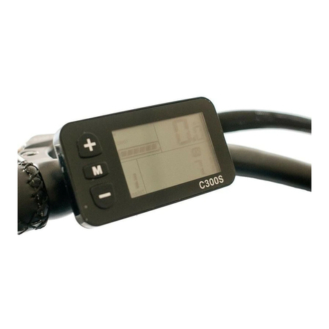
Innata brose Programming manual

1
04/10/2017
USAGE AND
MAINTENANCE MANUAL
CEB S.r.l.
Via Luigi Abbiati 22/C
25131 Brescia
Tel. 030 3539025
Fax 030 3539045
email: info@innata-ebike.it
ID: Usage and Maintenance Manual INNAT-B
R0.1
Brose system eBike
Dear Customer, Congratulations!
He has just bought one of the electric bicycle models with assisted pedalling produced by CEB s.r.l.
Equipped with components from Italian, German and Japanese leading companies.
Use it with caution and have fun!

2
04/10/2017
1. This manual is an integral and essential part of all INNATA electric bicycles.
2. Before any operation, carefully read the manual and the warnings contained therein, as they
provide important information and instructions regarding safety, use and maintenance.
3. This bicycle must be for the intended use only. Each different use is to be considered improper
and therefore potentially dangerous.
4. CEB s.r.l. cannot be held liable for damage caused to persons or things, to misuse, erroneous
or unreasonable use.
5. CEB s.r.l. is responsible for the product in its original configuration.
6. CEB s.r.l. is not responsible for the consequences of the use of non-original components.
7. CEB s.r.l. is not responsible for the consequences of intervention on the INNATA vehicle
performed by staff not expressly trained and qualified.
8. Any use or intervention that alters the original structure of the INNATA vehicle must be
exclusively authorized and executed by CEB s.r.l. or by people or companies expressly
authorized.
9. CEB s.r.l. is held responsible for what is written in the original version of this manual in Italian
language.
10. CEB s.r.l. reserves the right to make any changes to this manual and to any product without
prior notice in order to correct any errors, integrate new features or improvements.
11. For any problem or controversy, the updated Italian language version text has to be considered
as effective and its downloadable from the official website www.innata-ebike.it.
12. CEB s.r.l. applies to the product 24 months’ warranty, except for improper use or tampering.
For specific details see chapter WARRANTIES.
This manual is a restricted property of CEB s.r.l. Reproduction and disclosure without the
permission of the Company is prohibited.

3
04/10/2017
INDEX
DRAWINGS................................................................................................................................................ 4
QUICK USAGE GUIDE.............................................................................................................................. 6
USAGE AND MAINTENANCE (SECURITY) ............................................................................................ 7
BICYCLE PREPARATION ...................................................................................................................... 10
CONTROL DISPLAY UNIT ..................................................................................................................... 11
BATTERY INSTALLATION AND REMOVAL .......................................................................................... 15
BATTERY HANDLING AND CHARGING ............................................................................................... 16
PROBLEM RESEARCH AND TROUBLESHOOTING ............................................................................ 18
DISPOSAL ............................................................................................................................................... 20
WARRANTIES ......................................................................................................................................... 21

4
04/10/2017
DRAWINGS 1
1 Engine cover and crank
4 Display Unit buttons
2 Display Unit installation and removal
3 Display Unit safety lock
5 Display Unit functions
6 Control Unit buttons

5
04/10/2017
DRAWINGS 2
7 USB interface
8 Speed sensor and magnet
9 Battery kit
10 Battery kit installation and removal
11 Battery kit recharge connection
12 Battery charger

6
04/10/2017
QUICK USAGE GUIDE
This section summarizes all the basic operations that will allow you to start using quickly your INNATA
eBike motorized by BROSE.
Step1 Battery kit installation
Step2 Battery kit charging/connection
Step3 Battery kit locking
Step4 Display Unit connection
Step5 Activate Brose engine by clicking the
button on the led charge indicator of the
Battery kit
Step6 Select the assistance level by clicking
on the Control Unit placed on the handlebar

7
04/10/2017
USAGE AND MAINTENANCE
INSTRUCTIONS FOR YOUR SAFETY
Carefully follow all the instructions in the manual, paying particular attention to paragraphs titled in red.
Not following these instructions may result in electric shock, fire, and/or serious injuries.
Carefully keep this manual in case of future consultations.
In this manual Battery Kit or more simply Battery indicate both the model mounted on the crossbar of the
frame and the one in the rear luggage compartment.
For any reference, however, is relevant the latest version available at www.innata-ebike.it
REFERENCE LEGISLATION
The electrical pedal assisted bicycle is covered by the 2002/24/CE directive, which compares it to a
normal bicycle with an electric motor installed, connected to a battery, that lightens pedalling and which
automatically disconnects at 25Km/h.
The assisted pedal bicycles are regulated by Article 50 of the New Road Code and from the European
regulation EN15194, called EPAC (electrically power assisted cycle).
CAUTION
The bicycle is a vehicle that requires physical effort.
Consult your doctor for any contraindications you may have regarding your health using the bicycle.
CAUTION
Bicycle use is governed by the provisions of the current Highway Code.
If present, use the bike paths in the direction of travel whether it’s indicated.
Improper bicycle use can cause accidents, physical injuries, death.
It is recommended to use the helmet.
BICYCLE MAINTENANCE
Before any maintenance operation, it is recommended to remove the Battery Kit (26), as in case of
accidental triggering of the eBike system there would be a risk of being hurt, even seriously.
The bicycle is a mechanical vehicle subjected to stress.
It is therefore recommended:
•Periodic check of all mechanical clamps after the first 200Km and anyway every 2 or 3 months,
please refer to CEB s.r.l. or qualified mechanics.
•Check tire usury and tire pressure regularly.
•Leakage and setting test of the bicycle spokes.
•Check the wear condition of the braking system.
•Check the wear of the braking path rim and of the break discs.
•BROSE engine does not require any maintenance, any unauthorized intervention on the engine
immediately decay its warranty.
It is highlighted that wheels and chain are the most stressed and worn-out components and, therefore,
it’s recommended special attention and careful checking at the end of every use of the eBike.
For any problem, please contact CEB s.r.l. or a trusted mechanic.

8
04/10/2017
CLEANING THE BICYCLE
The bicycle can be cleaned using a damp cloth in warm water with, optionally, the addition of specific
detergents.
CAUTION
Before washing, remove the Battery Kit (26) and the Display Unit (1).
Do not use high pressure water jets directly on the Engine, Battery, Display Unit, and Wirings.
Before use make sure that there is no water stagnation on the Electrical Components, Cables,
Connectors, Batteries.
After cleaning, replace the lubricants on moving components.
Pay particular attention to the Hanger (31) before inserting Battery, checking its cleanliness and integrity.
CAUTION
The energy available at the minimum effort on pedals PROHIBITS to climb on the bicycle with the
powered engine on, taking advantage of the pedal support to climb.
The BROSE engine sensing the effort applied to the pedal starts almost instantly to deliver power and
the bicycle could then get out of hand.
In addition to damage the bicycle, the manoeuvre may cause you to lose balance, resulting probably in
physical damage and further damage to the vehicle.
CAUTION
Bicycle shelter and/or parking
Avoid to leave the Battery exposed to the sun or sever weather for long periods of time. Temperatures
excessively high or too low can damage the battery, or reduce its life significantly. It is recommended to
take and store in a cool place.
Minimum and maximum storage temperature: -10 / + 40ºC
Minimum operating temperature: -5 / + 40ºC
For long stops or transport of the eBike we recommend removing the Battery Kit.

9
04/10/2017
Battery life can be extended by making sure that each component of your battery is stored in the ideal
conditions as shown in the table.
Temperature
18-23°C
Humidity
0-80%
Level of charge
70%
GENERAL REMARKS
Do not make any change to the eBike system.
Do not try to improve the performance of the eBike system, these operations reduce the lifetime of the
BROSE system or even damage it.
Such unauthorized interventions will immediately terminate any form of warranty and may put at serious
risk both your own health and the health of others.
Carefully respect the national rules for the possession and use of an eBike.
Please read the instruction manual carefully, paying particular attention to notes regarding the BatteryKit
(26).
Be careful about the integrity of wirings, as the accidental contact between the live parts to each other or
to other eBike metal components may cause damage or fire.
After a distance of 15,000 Km it is advisable to inspect the Drive Unit at a BROSE authorized service
centre.

10
04/10/2017
BICYCLE PREPARATION
The BROSE system mounted on your eBike INNATA only works when the Display Unit (1) is properly
installed in its housing (2-3), the motor is connected to the Battery Kit (26) (charged) and the Speed
Sensor (25) is connected to the Engine with the Magnet (23-24) correctly aligned with the referenced
notch on the Sensor.
The electric motor start (Button (28)) must be done with pedals still, with no force applied the pedals.
The BROSE system allows and guarantees the cyclist assistance through the electric engine with an
assisted-pedal system (PEDELEC).
This assistance depends on the force applied by the cyclist to the pedals.
Therefore, PEDELEC assistance is only guaranteed if the cyclist is pedalling.
This is regardless of the assistance level set.
The eBike system is automatically deactivated when it exceeds 25 Km/h.
If the speed drops below 25 Km/h, the eBike system will restart automatically.
An exception is the Help function button (20) that allows you to push the eBike by hand at low speed,
without the need to pedal.
This function is achieved by pressing the button (20) until the service levels are excluded and then
maintained pressed for a few seconds.

11
04/10/2017
INNATA can also be used as a normal bicycle, without help, simply turning off the BROSE eBIKE system
button on the Battery Kit (28) or pushing the button (20) and bringing the level of assistance on OFF
(CRUISE, TOUR, SPORT "9" power off indicators).
The same happens with Battery (26) discharged, with led indicators (27) turned off.
Do not be overwhelmed by the enthusiasm of using the eBike INNATA, take the time you need to get
used to the eBike BROSE system before you venture into normal traffic conditions or on challenging off-
road routes.
Try/Test/Experience different levels of assistance until you feel comfortable in handling the INNATA eBike
system.
Before you venture on long journeys, gain experience on how the different parameters and environmental
conditions act on your eBike's range, that will avoid unpleasant muscle soreness.
LOSS OF THE eBIKE SYSTEM’S POWER
To protect Drive Unit from overload or overheating (for instance on a challenging hill), it has an automatic
power reduction system.
The Drive Unit initially reduces its power by 50%.
If the overload persists, the unit shuts down completely (error code "44").
ENGINE DATA
BROSE Material Identification Number
C16162
Dimensions
213 x 150 x 128 mm
Weight
3.400 g
Supply voltage
36 Vdc
Protection class
IP56 (protection against strong jet water and water)
Torque max.
90 Nm
Power
250W
Maximum speed
25 Km/h
Operating temperature
-10º + 50ºC
CONTROL DISPLAY UNIT
CONNECTION
Figure 2: Install the Dispaly Unit (1) by inserting it from the top of the Support (2).
Slide down the Display Unit along all the length of the Support until you hear it closing correctly.
To prevent it from being removed, tighten a suitable screw (4), making sure that it does not damage the
support.
DISPLAY UNIT REMOVAL
Turn off the Display Unit by pressing the Button (8) on the top.
Unscrew any Anti-Removal Screw (4).
Keep pressing down Lever (3) and push up the Display Unit by sliding it along the guides until it has left
the Support (2).
A buffered internal memory ensures thatyour historical data (eg clock, miles per day, pedalling time, etc.)
are maintained.

12
04/10/2017
PUTTING INTO SERVICE
After inserting the Display Unit into the Support, no other operation is required.
The system is ready to operate (if all the BROSE system devices are properly connected and the Battery
kit is sufficiently charged).
Press the Button (28) to activate the Battery Kit (26).
N.B.
The Display Unit does not have its own battery and therefore it cannot operate independently, so it must
Be installed properly in its Support.
As soon as the Battery Kit (26) is on, the Display Unit (1) lights up and stays on both during pedalling and
with the engine off.
If the eBike is not moving the Display Unit switches into standby mode after a few seconds.
Pressing for less than 2 sec. the Button (8) will resume the Display Unit.
Pressing for less than 2 sec. the button (8) can be used to force the standby mode.
The battery will remain in "Active Mode" for two hours.
As soon as the eBike restarts, the BROSE system will be reactivated and INNATA will be ready for use.
To minimize power consumption after two hours in "Active Mode" without any activity, the Battery Kit
automatically switches to "Deep Sleep Mode" and the Display Unit switches off permanently.
The "Deep Sleep Mode" mode is also activated by pressing the Button (28) on the Battery Kit for more
than 3 sec.
or by pressing the Button (8) on the Control Unit or when the Battery Kit is disconnected from the eBike
for more than 30 sec.
You can exit from the "Deep Sleep Mode" by pressing the Button (28) on the Battery Kit or by pressing
the Button (8) on the Display Unit (1) for more than 3 seconds.
There is a USB port with a capacity of max 500mA.
In the bottom of the Display Unit (1), open the Cover (21) to access the USB port (22).
DISPLAY FUNCTIONS
Display Unit shows different useful information. Figure 5:
Assistance level (9),
hand shifting activities (11)
speed,
battery charge level (13) each mark=10%
lighting mode activated (14)
multifunctional panel (15)
BRIGHTNESS
The bright background is 100% active whenever you press the Light Button (7) on the side of the Display
Unit.
During the night, the bright background is always active with a lower intensity so you do notdazzle cyclist.
Brightness is automatically adjusted based on ambient light.

13
04/10/2017
BATTERY CHARGING INDICATION
the charge level (13) is shown in 10 segments.
Each segment corresponds to a 10% charge.
If the charge level is less than 20%, the remaining segments will start blinking.
When the Battery charge level is less than 6%, the BROSE system turns off, removing engine assistance,
in order to make sure that each light can still work for about 2 hours if necessary.
SET UP DISPLAY UNIT
Pressthebutton(6)on theDisplayUnit(1) side ortheButton(19) of the ControlUnit(16) on the handlebar
to change and choose between the available functions.
DATA SHEET
BROSE Material Identification Number Display Unit
C54764
BROSE Material Identification Number Control Unit
C54760
Display Unit Dimensions
44.0 x 62.5 x 8.0 mm
Display Size
38.0 x 50.0 mm
Control Unit Dimensions
18.0 x 46.0 x 19.75 mm
Display Unit Weight
67 g
Protection class
IP65
Working temperature
-10º + 60º
Storage temperature
-20º + 85ºC
USB Voltage
5Vdc
Maximum power USB port
500 mA
AVAILABLE FUNCTIONS
"Range Time"
Distance travelled
Average speed
Time spent
Pedal resistance
Total Kilometres
Total time spent
Clock
Some functions can be disabled depending on the bicycle model. More information is available contacting
CEB s.r.l.
CHANGE UNIT OF MEASUREMENT
Turn off the Display Unit (1) by pressing the On/Off button (8) for less than 2sec.
Press simultaneously the On/Off Button (8) and the Menu Button (6) for more than 3 seconds until the
Multi-Function Panel (15) will display the software version.
All units of measurement on the display can be modified Km and Mi, Km/h and Mi/h.
WATCH SETTING
Press the Menu Button (6) until the Clock Function is displayed in Multifunctional Field (15).
Press the Menu Button (6) for more than 2 sec. until the time flashes, use the Set Assistance Level
Buttons (18) and (20) to adjust the time, press the Button (6) again and repeat the operation to change
minutes.

14
04/10/2017
Confirm your choice using the Button (6) or the Button (19) of the Multifunctional Panel (16) located on
the handlebar.
RESET MODE TRIP
Press the Button (6) on the Display Unit (1) or the Button (19) on the Multifunctional Panel (16) and
choose the desired function.
Press the Buttons (6) or (19) for more than 2 seconds. Until the function is reset.
TOTAL TIME RESET
Press the button (6) and select "Total Time".
Press Button (6) for more than 2 sec. Until the function is reset.
SOFTWARE VERSION VISUALIZATION
Press the On/Off button (8) briefly (for less than 2 sec.).
The Dispaly Unit shuts down.
Press and hold the On/Off button (8) for more than 5 sec.
In the Multifunctional section (15) of the display, the software version currently loaded will be displayed.
CONTROL UNIT
Your BROSE system installed on INNATA has 3 levels of assistance:
OFF, no engine assistance.
CRUISE, the cyclist dominates the light but perceptible engine assistance.
TOUR, the engine increases its assistance but the cyclist's strength is still present.
SPORT, full power from the engine, minimal effort from the cyclist.
Button (18) increments
Button (20) decreases
ON/OFF ASSISTANCE BUTTON
Assistance mode is used in special situations where minimal engine contribution is required without the
need to pedal.
Pressing the Command Unit (16) the Button (20) until the assistance level is Off, then holding it pressed,
the Assistance function (11) is activated.
Assistance remains active as long as the Button (20) remains pressed and it is disabled if released. In
this mode the engine pushes and limits the speed at 3 Km/h.

15
04/10/2017
BATTERY INSTALLATION AND REMOVAL
CENTRAL BATTERY or DOWNTUBE
Inserting the battery
1. Carefully position the Battery(26) in the Housing (31) by carefully sliding the Batteryon the appropriate
anchorage.
2. Push the Battery so that it locks and that it is perfectly adherent to the Housing (31).
3. Tighten the Battery with the appropriate Key (29) supplied, the cylinder has to fit into the Housing. (31)
4. Connect the Power Supply Connector to its Socket (30) securely
hooking.
Removing the battery
1. Turn off the system pressing the Button (28)
2. Turn the key (29) in the lock until the cylinder is ejected from the Housing.
3. Pull out the battery by pushing upwards.
4. Place the battery in a dry and safe place away from sources of heat and children's reach.
REAR LUGGAGE CARRIER BATTERY
Inserting the battery in the rear luggage carrier housing:
1. Carefully place the battery on the support located on the rear luggage carrier by doing so pass the
black metal stirrup inside the slot provided under the Battery.
2. Carefully push in the direction of travel until the battery locks with the holder (if necessary, rotate the
key to facilitate the locking)
Removing the battery from the rack:
1. Turn off the system
2. Turn the key in the lock counterclockwise,
3. Pull the battery along the luggage rack slot, in the opposite direction to the direction of travel
4. Place the Battery in a dry and safe place away from sources of heat and the reach of children.

16
04/10/2017
HANDLING AND CHARGING THE BATTERY
WARNINGS
Always pay extreme attention to handling the Battery (26) avoiding any impact.
Only use original power supplies (33) for charging.
If you need to purchase and/or replace the power supply, use only those supplied by CEB S.r.l.
Never short-circuit the battery by connecting the electric contacts, this will irreparably damage the battery
and it can cause sparks, explosions or fire.
The user cannot perform battery maintenance.
Never try to open the Battery. Opening the Battery entails serious risks to the user (explosions,
fire) and you lose any kind of warranty.
Do not use damaged Batteries.
Do not use the supplied Battery Charger (33) to charge other Batteries.
When charging with the Charger connected to the power grid and/or turned on, you must ensure that the
Battery
and the Battery Charger are not damp or wet in order to avoid short circuits resulting in fire. They have
to be placed
away from flammable objects or surfaces.
Do not use the Battery Charger whether the Cable, Body or Plug is clearly damaged.
Do not allow children to use the Battery Charger.
Lithium batteries have very low discharge currents (approximately 5% monthly), but if not
used have a permanent loss of charge capacity (see indicative table)
Storage Temperature
40% Charge
100% Charge
0°C
2% loss after 1 year
6% loss after 1 year
25°C
4% loss after 1 year
20% loss after 1 year
40°C
15% loss after 1 year
35% loss after 1 year
60°C
25% loss after 1 year
40% loss after 1 year
The battery must be recharged in a ventilated place, avoiding exposure to heat sources. Use power
supply grid built as required by current regulations.
Charging at too high or too low temperatures damages the cells and causes a significant reduction of
battery life.
Therefore, we recommend recharging the battery at room temperature (about 20°C). Before charging,
leave the battery at room temperature so that the battery can stabilize, this way it maintains maximum
efficiency and saves the accumulator from any damage.
It is possible to charge the Battery both on the bicycle and separately.
The lithium cells don’t have any memory effect, so you don’t have to wait for the battery to be completely
discharged before charging; you can charge it after each travel.
However, if possible and compatible with the route you intend to do, it is recommended to recharge the
battery only when charging indicator is at least at 50% of capacity.
If the battery will remain unused for a longer period of time (e.g. for a winter break), we recommend to
take it to 70% charge before the unused period.

17
04/10/2017
IMPORTANT
Check that for unused batteries the charge never drops below 50%.
Store unused batteries at 20 ° C (ideal temperature 18-23°C).
Compliance with the rules significantly increases battery life.
Failure to comply with the rules will invalidate the warranty.
Store unutilized battery in a cool place at a temperature between 18-23°C.
Never store the battery in places where the temperature exceeds 40°C or less than 0°C.
The battery should never be subject extreme temperature fluctuations and, during storage, it must
be protected against moisture to avoid corrosion of the electric contacts.
Battery both in use and in rest must always be protected from heat and shock or hits.
Never use damaged batteries.
The use of damaged batteries is potentially dangerous to the safety of people.
The battery runs properly within a temperature between 5°C and 40°C. The autonomy of the battery is
reduced if used outside of these values.
To keep it in good condition, the Battery is recommended to removing it from the bicycle if you park for a
long time in the sun or in the rain.
If well maintained and stored, the supplied Battery provides a minimum of 500 full charge cycles.
RECOVERY PROCESS
Each Battery (26) needs its own Battery Charger (33).
It is recommended to use a battery charger approved by the manufacturer.
Time required for charging is variable and depend on charging status, battery capacity, and from the
power of the supplied Battery Charger (typically 5-8 hours fully discharged battery).
Chargers automatically disconnect when charging is complete,nevertheless the battery, at the end of the
charge, should not remain connected for a long period to the Battery Charger and power supply.
1. Connect the cable (35) to the Battery Charger (36) and to the 230Vac household power supply
making sure that it corresponds to the specifications of the Charger included.
2. Connect the Battery Charger (33) to the Cable (32) to the Jack (30).
3. LEDs on the display (34) should turn on flashing LEDs.
4. The Yellow LEDs (27) on the Battery Kit flash indicating the charge status.
5. The Charger is now operating.
6. At the end of the charging process, the status LED (34) will switch from intermittent to fixed, the
battery is charged.
7. All the yellow LEDs on the Battery Kit (27) will be switched on.
8. Disconnect the Charger Cable (32) from the Jack (32).
9. Disconnect the Charger Cable (35) from the home power grid and then from the Battery Charger
(33).
AUTONOMY
The battery's autonomy depends on various factors such as, for instance,
- pedal support mode set on the Display Unit (Cruise, Tour, Sport),
- type and difficulty of the path,
- weight of cyclist and bicycle,
- speed,
- temperature and wind on the path,
- type of tires and their pressure,
- pedalling quality and gear ratio used.

18
04/10/2017
CEB S.r.l. recommends that you choose the assistance mode as needed, remembering that less fatigue
will result in higher power consumption and less battery life.
The PEDELEC system supports the cyclist in proportion to its capacity and, therefore, reaches
automatically the best efficiency.
LED on
flashing LED
Charge level
-
1
0-19%
1
2
20-39%
1,2
3
40-59%
1,2,3
4
60-79%
1,2,3,4
5
80-99%
1,2,3,4,5
-
Complete charge 100%
PROBLEM RESEARCH AND TROUBLESHOOTING
Before anyaction, if you encounter any problem during the use of yourBROSE motorized INNATA eBIke,
check all the examples in the tables below.
This will allow you to solve the problems by yourself in most cases.
Thank you for your cooperation.
Problem
Possible cause
Solution
The Display Unit and/or the eBike
BROSE system do not start
Battery Kit (26) doesn't work even if
charged
Press the Button (28) to check if the Battery
Kit (26) is on. LEDs (27) should turn on on the
Battery Kit (26). If this is not the case, the
Battery Kit (26) is defected. Contact the
manufacturer.
Battery Kit (26) not installed properly on
its Support (31)
Remove the Battery Kit (26) and re-insert it.
Make sure it is well positioned and locked.
Battery Kit (26) out of charge
Complete to charge the Battery (26) using the
provided Charger (33)
Dirt between the Battery (36) and the
Support (31)
Clean with a dry cloth or a brush
Dirt between the Socket (30) and the
Cable (32)
Clean with a dry cloth or a brush. Where
appropriate use electric contacts detergents.
Dirt between the Display Unit (1) and the
Support (2)
Clean with a dry cloth or a brush. Where
appropriate use electric contacts detergents.
Faulty contact between the Display Unit
(1) and the Support (2)
Remove the Display Unit (1) and re-insert it.
Make sure it is well positioned and locked.
Wirings, Sockets and Jacks not inserted
properly
Check connections and restore them properly
if necessary.
The Display Unit doesn't display
pedalling data properly even if
the eBike is active
The magnetic sensor is not positioned
properly
Check the relative position of the Magnet
(23-24) applied to the spoke and the Sensor
(25) located on the eBike chassis. It must be
aligned with the reference notch on the
Sensor (25) at an ideal distance between 5 to
17mm.
Front/rear lights do not turn on (if
installed)
Disconnected wiring
Check the connections and restore them
properly if necessary.
The Display Unit shows an error
code
There is an activation error in the system
Check the table below

19
04/10/2017
Error code
Description
Solution
10
The battery voltage is too low.
Charge the Battery (26) using the Charger (33)
11
The battery voltage is too high.
Fully turn off the BROSE system. Press the Button (28) on the
Battery Kit (26). If the problem persists contact the eBike
provider.
12
The battery is almost completely discharged.
Charge the Battery (26) using the Charger (33)
20
Incorrect electrical measurements,
Fully turn off the BROSE system. Press the Button (28) on the
Battery Kit (26). If the problem persists contact the eBike
provider.
21
Faulty temperature sensor.
23
24
Power problems internal to the system
Charge the Battery (26) using the Charger (33)
25
Motor electric current measurement error.
Fully turn off the BROSE system. Press the Button (28) on the
Battery Kit (26). If the problem persists contact the eBike
provider.
26
A reset software was executed.
30
Error in the Assistance function.
40
Detected overcurrent in the Engine.
Reduce engine load by pedalling less or reducing the assistance
level.
41
Detected overcurrent in the Engine.
Reduce engine load by pedalling less.
42
Engine malfunction.
Fully turn off the BROSE system. Press the Button (28) on the
Battery Kit (26). If the problem persists contact the eBike
provider.
43
Short Circuit in the engine.
44
Engine overheating
Reduce engine load by pedalling less or reducing the assistance
level. If necessary, turn off the BROSE system and proceed
muscularly.
45
The software corrected an error while the engine was
running.
Fully turn off the BROSE system. Press the Button (28) on the
Battery Kit (26). If the problem persists contact the eBike
provider.
46
No motion of the Engine is detected despite a current
greater than 2A has been detected.
60
Interruption of data exchange on the CAN/BUS system.
Check the cables and signal connectors of all components of
the BROSE eBike system.
70
Effort applied to the pedals is out-of-range.
Fully turn off the BROSE system. Press the Button (28) on the
Battery Kit (26). If the problem persists contact the eBike
provider.
71
No pedal movement is detected,
72
No force applied to the pedals is detected.
73
Error in the connection of the Pedal Stress Sensor.
80
Incorrect Engine Parameters.
81
Speed signal not detected.
Make sure that the Magnet (23-24) and the Sensor (25) are
correctly positioned.
82
The program has been manipulated.
Fully turn off the BROSE system. Press the Button (28) on the
Battery Kit (26). If the problem persists contact the eBike
provider.
83
Error in the program sequence.
84
Incorrect Engine Parameters.

20
04/10/2017
DISPOSAL
Battery (26), Battery Charger (33), Electric Motor, Control Unit (1), Wiring (3-16-32-35) and Mechanic
Parts are NOT garbage-like urban waste.
Each component of the electric bicycle must be disposed in appropriate differentiated collection centers
according to local provisions in force.
Table of contents
Popular Bicycle Accessories manuals by other brands
by.schulz
by.schulz D.1 Ri Installation and operating instructions
SRAM
SRAM RockShox Super Deluxe Flight Attendant user manual

KOLOFOGO
KOLOFOGO TAHOE User Guide, Directions For Use
Steadyrack
Steadyrack Classic Rack installation instructions
Cateye
Cateye OS 1.0 Setup guide
dbRevO
dbRevO Wireless Tech All-in -One Design Usage manual
