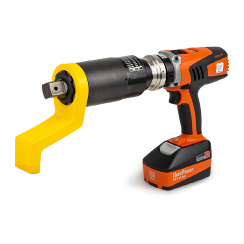
Inno Torc EMAX Series User manual

InnoTorc GmbH Instruction Manual EMA Page 1
Instruction Manual
Battery-Powered Torque Wrench, EMA series with TorcDoc

InnoTorc GmbH Instruction Manual EMA Page 2
Technical Data: EMA series
Torque ranges in accordance with characteristic curve for type. Please consult the calibration certificate for
precise values. All dimensions stated are approximate; technical specifications subject to change without notice
Model
EMA
40
EMA
80
EMA
150
EMA
300
EMA
450
EMA
600
Square drive shaft DIN 3121 ¾“ ¾“ ¾“ (1") 1" 1½" (1“) 1½"
Min. torque (Nm) 20 50 100 200 300 400
Max. torque (Nm) 450 800 1500 3000 4500 6000
Length A, without drive shaft (mm) 300 300 345 345 405 420
Overall height B, incl. gear holding ring and
battery (mm) 270
Diameter of gear holding ring C (mm) 78,0
Gear diameter D (mm) 77,0 90,0 102,0
Weight without support arm (kg) 4,9 5,2 6,1 6,2 8,9 11,0
Idling speed for Gear 1 (rpm) 18,0 9,0 5,0 2,5 1,5 1,0
Idling speed for Gear 2 (rpm) 54,0 27,0 15,0 7,5 4,5 3,0
Charger and batteries as per instructions from the company Fein

InnoTorc GmbH Instruction Manual EMA Page 3
Incoming goods inspection and packaging
Check the device and accessories for transport damage. If any damage is detected, please notify the
carrier immediately and return the device in its original packaging to InnoTorc or the responsible sales
partner. Please retain the original packaging.
Read these instructions before putting the device into service and make yourself familiar with the
procedure for handling it. Do not use the device if you are unsure of the purpose, the consequences
and the precise execution of the specific operation.
In particular, make yourself familiar with the safety instructions. Failure to observe them may result in
severe bodily harm.

InnoTorc GmbH Instruction Manual EMA Page 4
Safety precautions prior to commissioning and assembling the
device
Each time you use the device and accessories, inspect them for any damage. Devices that are
damaged or defective must not be put into service. Repairs may only be performed by the
manufacturer. Send any defective/damaged devices back to the manufacturer in the original
packaging.
Check whether the available mains supply voltage matches to the data on the identification plate of
the charger.
Only use the device for its intended purpose.
The noise level may exceed 85 dB(A) so you must always wear ear protection.
Observe any local, industry-specific regulations, such as the wearing of safety footwear, helmets,
gloves, etc.
Do not use the device in an explosive atmosphere or in the presence of inflammable liquids, gases,
paints, vapours or dust.
Do not use the device in rain or other damp conditions.
Before you insert the battery, assemble the socket and the support arm in accordance with the
illustration above. The socket together with the pin and the support arm must be fixed with the screw.
Make sure that these parts are correctly and completely in position. Do not use any defective or
damaged accessories.

InnoTorc GmbH Instruction Manual EMA Page 5
Safety precautions and performing the tensioning operation
[RICHTIG = CORRECT; FALSCH = WRONG]
Never hold the device at the front by the socket or support arm due to the risk of crushing and other
injuries! Under no circumstances should you reach into the space between support arm and support
point.
Set the desired torque. A power reserve of approx. 25% should be allowed for loosening bolts.
The socket must be placed completely onto the head of the bolt and must not be tilted. The
transmission axis must be in line with and not deviate from the axis of the bolt.
The support arm must rest securely on the adjacent bolt or on another fixed point. The supporting
point must be at the same height as the bolt. The support arm must be resting on the vertical side
surfaces.
Never block the operating button with any kind of aid. Always be ready to switch it off.
Only press the trigger switch lightly while the support arm is not firmly positioned on the resting point
so that the device is able to turn slowly. Do not press the trigger switch to its maximum extent until the
wrench is firmly in position.
The wrench switches off when the pre-set torque has been attained.

InnoTorc GmbH Instruction Manual EMA Page 6
Setting the switch off torque in torque mode:
Switch on the tool:
The EMAX torque tool is switched on by pressing the button . The main menu is shown in figure 1.
With the two buttons and , the individual menu items can be selected. Select the “Start Torque”
function. The selection is accepted by pressing the button .
Select Gear:
The choice of gear stage (power = gear 1, fast = gear 2) is selected by using the rotary switch on the
side of the tool. Care should be taken to ensure that the rotary switch is in the respective end position!
The selected gear stage is shown in the display. The torque ranges available for gears 1 and 2 are
each adjusted (gear 1 = full torque range, gear 2 = reduced torque range).
Select Torque:
The desired switch off torque can be specified in stages (figure 2). With the buttons – and + the
switch-off torque can be selected in fixed steps. The selection is done with the button . The display
changes to "Ready".
You can return to the higher-level menu by briefly pressing the button . Similarly, one of the three
buttons can be pressed to return to the higher-level menu.
Ready to start:
After torque selection, the tool is ready for operation (figure 3). The tool can now be started with the
rocker button in the handle. Pressing the lower half of the rocker starts the tool in clockwise rotation,
the upper half starts the tool in counter clockwise rotation. Releasing the rocker, or when the set
torque has been reached, the tool stops.
You can return to the higher-level menu by briefly pressing the button . Similarly, one of the three
buttons can be pressed to return to the higher-level menu.
Esc
Esc
Esc
Fig. 2: Select switch off
torque for gear 1
Fig. 1: Main menu Fig. 3: Tool is ready for
working in gear 1

InnoTorc GmbH Instruction Manual EMA Page 7
Setting the pre-torque and angle in torque + angle mode:
Switch on the tool:
The EMAX torque tool is switched on by pressing the button . The main menu is shown in figure 4.
With the two outer buttons and , the individual menu items can be selected. Select the “Start
Torque+Angle” function. The selection is accepted by pressing the button .
Select Gear:
In torque + angle mode, we recommend using only gear 1!
Select Pre-Torque:
The desired pre-torque can be specified in stages (figure 5). With the buttons – and + the pre-torque
can be selected in fixed steps. The selection is done with the button . The menu changes to "Angle".
You can return to the higher-level menu by briefly pressing the button .
Select Angle:
The desired angle can be specified (figure 6). With the buttons – and + the angle can be selected in
fixed steps. The selection is done with the button . The menu changes to "Ready" (figure 7). You can
return to the higher-level menu by briefly pressing the button .
Ready to start:
After above selections, the tool is ready for operation in torque and angle mode. The tool can now be
started with the rocker button in the handle. Pressing the lower half of the rocker starts the tool in
clockwise rotation, the upper half starts the tool in counter clockwise rotation. Releasing the rocker, or
when the pre-torque and the angle have been reached, the tool stops.
You can return to the higher-level menu by briefly pressing the button . Similarly, one of the three
buttons can be pressed to return to the higher-level menu.
Esc
Esc
Esc
Esc
Fig. 5: Select pre-torque
Fig. 4: Select torque and
angle mode
Fig. 6: Select angle Fig. 7: Tool is ready for
working

InnoTorc GmbH Instruction Manual EMA Page 8
Controls
Switch off the tool:
The tool is switched off by a long press on the button .
Esc
Fig. 9: Tool is working:
torque + angle mode
(Running clockwise)
Fig. 8: Tool is working:
torque mode
(Run
ning clockwise
)

InnoTorc GmbH Instruction Manual EMA Page 9
Options: Release Angle
Change Release Angle:
The automatic release angle of the tool can be specified in menu “Options” (figure 10 and 11).
With the buttons – and + the angle can be changed (figure 12). The selection is done with the
button . We recommend a release angle of no more than 20 degrees!
You can return to the higher-level menu by briefly pressing the button . Similarly, one of the three
buttons can be pressed to return to the higher-level menu.
Esc
Fig. 10: Options Fig. 11: Release angle Fig. 12: Change release angle

InnoTorc GmbH Instruction Manual EMA Page 10
Start a project without parameter import
General
Switch on the tool:
The EMAX torque tool is switched on by pressing the button . The main menu is shown in figure 13.
With the buttons and , the individual menu items can be selected. Select the “Start Project”
function. The selection is accepted by pressing the button .
Select Gear:
The choice of the gear stage (power = gear 1, fast = gear 2) is selected by using the rotary switch on
the side of the tool. Care should be taken to ensure that the rotary switch is in the respective end
position! The selected gear stage is shown in the display. The torque ranges available for gears 1 and
2 are each adjusted (gear 1 = full torque range, gear 2 = reduced torque range).
In torque and angle mode, we recommend using only gear 1!
Documentation:
In the “Start Project” submenu, the required pre-torque can be selected with the - and + buttons (figure
14). After accepting it with the button , the desired rotation angle is selected (figure 15). Next, the
limits of the desired tightening torque are selected by entering the minimum and maximum torque
values. (figure 16 and 17).
Esc
Fig. 14: Select pre-torqueFig. 13: Start project Fig. 15: Select angle

InnoTorc GmbH Instruction Manual EMA Page 11
After entering the number of screws (figure 18), an overview of the parameters entered appears (figure
19). The parameter set is given a name which is composed of the current date and time. After
pressing the button , the project is started (figure 20)
Ready to start:
Now, the tool is ready for operation. The tool can be started with the rocker button in the handle.
Pressing the lower half of the rocker starts the tool in clockwise rotation, the upper half starts the tool
in counter clockwise rotation. Releasing the rocker, or when the set torque has been reached, the tool
stops. You can return to the higher-level menu by briefly pressing the button . Similarly, one of the
three buttons can be pressed to return to the higher-level menu.
Esc
Fig.17: Maximum torque
Fig. 16: Minimum torque
Fig. 18: Number of
screws
Fig. 20: Start tightening
Fig. 19: Overview

InnoTorc GmbH Instruction Manual EMA Page 12
Start a project with parameter import
App installation:
The Android App TorcDoc from InnoTorc GmbH is required for the import parameter. Download it and
install it on a smartphone or tablet with Android. In the “Settings” menu item (figure 21), enter an e-
mail address for the data export and select the desired format. Finally, press the "Save configuration"
button.
Connect to torque tool:
Switch on the torque wrench. In the app select the item "Connect", a search will be started. As soon as
a device is found, it appears on the display. The coupling is carried out by clicking on the desired
device name. When connecting for the first time, you need the coupling code, ask the manufacturer for
this. When the app is connected to the torque wrench, the data is synchronized and the logs appear in
the app (figure 22).
Create and import projects:
You need a csv file to create the projects, an example file is included. You can create or edit the file on
the PC / laptop. You can create multiple users, projects, objects and parameter sets in this file. The
created file can e.g. be sent to the smartphone by email or you can use a cloud that you can access
with the smartphone. Save the file on the smartphone.
First make sure that there is a connection to the torque tool. In the app, select the item "Import
Configuration Data". This button is only active when there is a connection to the tool. A file manager
appears in which you can select the previously downloaded csv file. As soon as the file is clicked, the
transfer to the torque tool begins. When the transfer is finished, the tool is automatically switched off.
Fig. 21: Settings Fig. 22: Protocolls Fig. 23: Protocoll
preview

InnoTorc GmbH Instruction Manual EMA Page 13
Start Project:
Switch on the torque wrench. The previously created data file will now appear in the “Start project”
submenu. The individual menu items can be selected with the buttons and . The selection is
accepted by pressing the button . Select the user, then the project, an object and a parameter set
(figure 24-27).
After selecting the parameter set, an overview of the parameters entered appears (figure 28). After
pressing the button , the project is started (figure 29).
Tightening:
The torque wrench can now be started with the rocker button in the handle. The torque achieved
appears on the display after each screw connection (figure 29). If the torque is within the specified
minimum and maximum values, an "ok" appears. If the value is outside the limits, a "nok" appears.
After a parameter set has been processed, a protocol is saved in the tool. This can now be exported
using the app.
Fig. 29: Tightening
Fig. 28: Overview
Fig. 24: User Fig. 27: Parameter set
Fig. 25: Project Fig. 26: Object

InnoTorc GmbH Instruction Manual EMA Page 14
Export protocol:
First, make sure that there is a connection to the tool. As soon as there is a connection to the torque
tool, the data is automatically synchronized and the logs appear in the app. The desired protocol can
now be selected and viewed in the app (figure 23). To export, press the "Export" button. You can
choose whether the log should be sent by email or saved in a cloud. You can output the file either as a
pdf or as a csv file.
Delete protocol:
The logs are synchronized each time a tool is connected and displayed in the list with a new time
stamp. You can delete individual protocols in the “Protocols” menu item. Only the log is deleted from
the app. To delete the protocols in the torque tool, go to Settings and click on "Delete protocols In
Tool". This deletes all (!) logs in the torque wrench.

InnoTorc GmbH Instruction Manual EMA Page 15
Option: Testmode
The testmode is used to check the torque of a screw connection. If the screw connections is tighten
enough, the screw is not turned any further; with loose screw connections, the retightening angle is
shown on the screwdriver's display until the required tightening torque is reached.
Select Torque:
With the buttons – and + the test torque can be selected. The selection is done with the button . The
display changes to "Ready".
You can return to the higher-level menu by briefly pressing the button . Similarly, one of the three
buttons can be pressed to return to the higher-level menu.
Ready to start:
After torque selection, the tool is ready for operation. The tool can now be started with the rocker
button in the handle.
Test torque:
Pressing the lower half of the rocker starts the tool in clockwise rotation, the upper half starts the tool
in counter clockwise rotation. When the test torque has been reached, the tool stops automatically. As
long as the rocker is still pressed, the screwdriver's display shows the retracted angle. Releasing the
rocker deletes the post-rotation angle and the screwdriver can be started to test the next screw
connection.
Esc

InnoTorc GmbH Instruction Manual EMA Page 16
EC declaration of conformity
according to the EU Machinery Directive
2006/42/EC, Annex II 1.
A
Manufacturer
InnoTorc GmbH
Augsburger Str. 91
DE - 85290 Geisenfeld
Description and identification of the machinery
Product / Article Electric shut-off wrench EMAX Series
Project number PRJ-2020-03-01-0001
Function Battery-Powered Torque Wrench, for tightening and loosening screw connections.
It is expressly declared that the machinery fulfils all relevant provisions of the following EU
Directives or Regulations:
2006/42/EC Directive 2006/42/EC of the European Parliament and of the Council of 17 May 2006 on
machinery, and amending Directive 95/16/EC (recast) (1)
Published in L 157/24 of 09.06.2006
2014/30/EU Directive 2014/30/EU of the European Parliament and of the Council of 26 February 2014 on
the harmonisation of the laws of the Member States relating to electromagnetic compatibility
(recast)
Published in 2014/L 96/79 of 29.03.2014
2014/35/EU Directive 2014/35/EU of the European Parliament and of the Council of 26 February 2014 on
the harmonisation of the laws of the Member States relating to the making available on the
market of electrical equipment designed for use within certain voltage limits
Published in 2014/L 96/357 of 29.03.2014
2011/65/EU Directive 2011/65/EU of the European Parliament and of the Council of 8 June 2011 on the
restriction of the use of certain hazardous substances in electrical and electronic equipment
Published in 2011/L 174/88 of 01.07.2011
Reference to the harmonised standards used, as referred to in Article 7 (2):
EN ISO 12100:2010-11 Safety of machinery - General principles for design - Risk assessment and risk reduction (ISO
12100:2010)
EN 60204-1:2018 Safety of machinery - Electrical equipment of machines - Part 1: General requirements (IEC
60204-1:2016, modified)
EN 62841-1:2015 Electric motor-operated hand-held tools, transportable tools and lawn and garden machinery —
Safety — Part 1: General requirements
EN 62841-2-2:2014 Electric motor-operated hand-held tools, transportable tools and lawn and garden machinery —
Safety — Part 2-2: Particular requirements for hand-held screwdrivers and impact wrenches
(IEC 62841-2-2:2014, modified)
Geisenfeld, 01.03.2020
Place, Date
Signature
Jürgen Vogl
Geschäftsführer

InnoTorc GmbH Instruction Manual EMA Page 17
Servicing and manufacturer’s details
The device contains no components to be serviced or repaired by the end customer.
In the event of a malfunction, the display flashes and shows "E" followed by a two-digit error number.
Please make a note of this number and send the device to InnoTorc GmbH or the responsible sales
partner. Do not try to repair the device yourself.
After 10,000 screwdriving operations, “Service is due” appears in the display. You should send the
device to InnoTorc for maintenance as soon as possible.
We recommend a service and torque calibration every 12 months or after a maximum of 1,000
operating hours. Please send the device in its original packaging to the manufacturer or the respective
sales partner.
Manufacturer’s details
InnoTorc GmbH
Augsburger Str. 91
D-85290 Geisenfeld
This manual suits for next models
6
Other Inno Torc Power Tools manuals
