INNO View 12R User manual

1
User Manual
Please read this manual before
operating your fusion splicer,
and keep it for future reference.
2021/04 Rev.1.3

2
View 12R
User Manual

3

4
Contents
Introduction
Chapter 1: Technical specifications
Applicable fiber type
Splice loss
Splice mode
Heat oven
Power supply
Dimensions and weight
Environment
Other
Battery precautions
Chapter 2: Installation
Safety warnings and precautions
Operational safety warnings
Maintenance and external care precautions
Transport and storage precautions
Installation
Unpacking the splicer
Splicer overview
Power supply
Battery
Charge the battery
How to check remaining battery capacity
Battery refresh
Chapter 3: Basic Operation
Turning on the splicer
Adjusting the monitor position
Adjusting the monitor brightness
7
8
8
8
8
8
9
9
9
9
10
11
11
11
12
13
14
14
16
17
17
17
18
18
19
19
19
20

Contents 5
Touch screen On/Off
Fiber zoom function on screen
Preparing the fibers
How to make a splice
Placing the fibers
Inspecting the fibers
Splicing
How to protect the splice
Heating procedure
Chapter 4: Splice Programs
Displaying the active splice program
Selecting a splice program
General splicing steps
Pre-fusion
Fusion
Splicing process
Splice program parameters under general splicing process
Chapter 5: Splice Option
Setting up splice mode
Chapter 6: Heater Mode
Selecting heater mode
Editing heater mode
Deleting heater mode
Heater mode parameters
Chapter 7: Maintenance Menu
Replace electrodes
Replacement procedure
Stabilize electrodes
Operation procedure
Diagnostic test
20
21
21
22
22
22
23
24
24
25
25
26
27
27
27
27
28
30
30
32
32
33
34
34
35
35
35
36
36
36

Contents 6
Operation procedure
Motor calibration
Arc calibration
Operation procedure
Electrode setting
Update software
Chapter 8: Other Functions & Utilities
Data storage
Display splice record
Delete splice record
Cancel data storage
System setting
Monitor position
Power save option
System information
Appendix I: Reasons for high splice loss and solutions
Appendix II: List of error messages
Appendix III: Frequent questions and troubleshooting
36
37
37
38
38
39
40
40
40
40
40
41
42
43
43
44
46
49

7
Important: INNO Instrument strongly recommends all users to read this manual
before operating VIEW 12R.
This manual is valid for the following software version:

8
Introduction
Thank you for choosing VIEW 12R Arc Fusion Splicer from INNO Instrument.
View 12R adopts innovative product design and exquisite manufacturing
technology so as to deliver unprecedented splicing experience to customers.
The totally new technology greatly reduces splicing and heating time, and
advanced estimation method and alignment technique ensure the accuracy
of splice loss estimation. The simple-but-trendy product design, sophisticated
internal structure and reliable protective cover make the splicer be suitable for any
operating environment. Dynamic operation interface and automatic splice mode
provide users great convenience. For more information of VIEW 12R,
please visit our official website at www.innoinstrument.com

9
Technical Specifications
Applicable fiber type
•SM(ITU-T G.652 & G.657) / MM(ITU-T G.651) / DS(ITU-T G.653)
/ NZDS(ITU-T G.655)
•Fiber count: Single to 12 cables
•Applicable fiber cables: Ribbon: 0.25mm- 0.4mm / Single: 250μm & 900μm
•Applicable fiber diameter: Cladding diameter: 125μm
Splice loss
Measured by cut-back method relevant to ITU-T standard:
•SM : 0.05dB
•MM : 0.02dB
•DS : 0.08dB
•NZDS : 0.08dB
Splice mode
•Maximum 100 splice modes
•Internal splice data storage: 2000
•Splicing time: Ribbon fiber: 15s / Single fiber: 9s
Heat oven
•5 applicable protection sleeve: Micro, 40mm, 50mm, 60mm
•Heating time: 8-900s
•Typical heating time: 20s
•Heat mode: Maximum 32 modes
•Heat oven: VIEW 12R special heat oven
1

Chapter 1 Technical Specifications 10
Power supply
•Standard AC power voltage: AC 100-240V, 50-60Hz
•Standard DC power voltage: DC 9-14V
Dimensions and weight
•Size: Height x Width X Depth = 167mm x 143mm x 163mm
•Weight: 2.64kg (battery included)
Environment
•Operating condition: 0~3,660m above sea level, 0~95% relative humidity,
-10~50℃, 15m/s max wind speed
•Storage condition: 0~95% relative humidity, -40~80℃
•Battery: -20~30℃for long time storage
Other
•Viewing and displaying method: two cameras and 5.0 inch color LCD monitor
•250x magnification for single X or Y view, or 250x magnification for
both X and Y view.
•Tensile test: 1.96-2.25N
•Terminals: DIN / USB Type-C

Chapter 1 Technical Specifications 11
Battery precautions
•DO NOT collide the battery with sharp or hard objects.
•DO NOT transport or store the battery with metals simultaneously.
•DO NOT throw, drop, impact or bend the battery.
•DO NOT strike the battery with hammers or tread on it.
•DO NOT connect the anode and cathode of the battery to metals such as
electrical short circuit.
•DO NOT let the anode and cathode contact with the external aluminum coating
of the battery so as to avoid short circuit.
•DO NOT disassemble the battery under any circumstances.
•DO NOT immerse the battery in fresh water or sea water, and avoid moisture.
•DO NOT use or place the battery near heat source. (e.g. fire, heat oven)
•DO NOT heat the battery or throw it into water.
•DO NOT weld the battery directly.
•DO NOT charge the battery near fire or in high temperature.
•DO NOT put the battery into the microwave oven or high pressure container.
•DO NOT use or place the battery in extremely high temperature
(e.g. strong sunlight or inside a car which is with poor ventilation) for long period
of time. Otherwise, it may cause overheat, fire, battery malfunction, or shorter
battery life.
•DO NOT use damaged battery. The battery with electrolyte leakage or electrolyte
smell shall be kept away from fire to avoid fire or explosion.
•If electrolyte leakage contacts with skin or other parts of body, please wash it off
with a plenty of water immediately. If electrolyte leakage contacts with your
eye(s), please rinse your eye(s) with water immediately and seek medical advice.

12
2
Installation
Safety warnings and precautions
As VIEW 12R is designed for fusion splicing silica glass optical fibers, it is very
important that the splicer should not be used for any other purposes. The splicer
is a precision instrument and must be handled with caution. Therefore, you must
read the following safety rules and general precautions in this manual regarding the
use and handling of VIEW 12R at any time. Any behaviors that do not follow the
warnings and cautions will break the safety standard about design, manufacture,
and usage of the fusion splicer. INNO Instrument will not take the responsibility for
those consequences caused by misuse!
Operational safety warnings
•Never operate the splicer in an environment where flammable liquids or vapors
exist.
•DO NOT touch the electrodes when the splicer is on.
Note: Only use specified electrodes for the fusion splicer. Select [Replace
electrode] in maintenance menu to replace electrodes, or turn off the splicer and
disconnect the AC power source or remove battery before replacing electrodes.
Discharging is prohibited before the electrodes are placed as a pair.
•DO NOT disassemble or modify any components of the splicer without approval,
except for the permitted-to-disassemble / modify components or parts by users
stated in this manual. Component replacement and its internal adjustment must
be implemented by INNO Instrument or its authorized technicians or engineers.
•Never operate the splicer in an environment where flammable liquids or vapors
exist. Risk of dangerous fire or explosion could result from the splicer’s electrical
arc in such an environment. DO NOT operate the splicer near hot objects or in
high temperature and dusty / humid atmosphere, or when condensation is
present on the splicer. This may result in electric shock, splicer malfunction,
or poor splicing performance.

Chapter 2 Installation 13
•Users should always wear safety glasses during fiber preparation and splicing
operation. Fiber fragments can be extremely dangerous if they are ingested or
come into contact with eyes, skin.
•Take out the battery immediately if the followings are observed when using
the splicer:
•Fumes, bad smell, abnormal noise or over heat.
•Liquid or other matter falls into cabinet
•The splicer is damaged or dropped.
Note: If any of these faults occurs, please contact our service center
immediately. Leaving the splicer in a damaged state without any prompt
measures may cause equipment failure, electric shock, or fire and may result in
injury or death.
•Do not use compressed gas or canned air to clean the splicer. They may contain
flammable materials that could ignite during the electrical discharge.
•Please use VIEW 12R designed battery only. Using an improper AC power
source
may cause fuming, electric shock or equipment damage and may even result in
fire, injury or death.
•Please use VIEW 12R designed charger only. Do not place any heavy objects on
the AC power cord. Keep the power cord away from heat source. Using an
improper cord or a damaged cord may cause fuming, electric shock or
equipment damage and may even result in fire, injury or death.
Maintenance and external care precautions
•Always avoid using hard objects to clean V-grooves and electrodes.
•Always avoid using acetone, thinner, benzol or alcohol when cleaning any parts
of the splicer, except for the places advised.
•Use a dry cloth to remove dust and dirt from the splicer.
•If the outside of the splicer is dirty, plunge a soft cloth into diluted neutral
washing up liquid, wring out the cloth and clean. Dry the splicer with a dry cloth
but DO NOT USE furniture polish or other cleaning agents.
•Always follow the maintenance instructions in this manual.

Chapter 2 Installation 14
Transport and storage precautions
•When the splicer is moved from cold to warm environment, you should allow the
splicer to warm up gradually. Otherwise, the condensation generated inside will
bring harmful effects to the splicer.
•Pack the fusion splicer well for long time storage.
•Keep the splicer clean and dry.
•The splicer is precision adjusted and aligned. Always keep the splicer in its
carrying case to protect from damage and dirt. Put cushion package outside the
carrying case for long distance transportation.
•Always avoid leaving the splicer in direct sunlight or expose to excessive heat.
•DO NOT store the splicer in dusty or humid environment. This may result in
electric shock, splicer malfunction or poor splicing performance.
•Keep the humidity to a minimum level where the splicer is stored. The humidity
must not exceed 95%.

Chapter 2 Installation 15
Installation
Important: Please follow the instructions below carefully.
Unpacking the splicer
Hold the handle upwards, then lift the splicer out of the carrying case.
Package
⑪Battery Pack
⑫Power Cable
⑬USB Type-C to USB Cable
⑭DIN Cable
⑮ Protection Sleeves
⑯ V-Groove Cleaning Brush
⑰Carrying Case
①VIEW 12R
②High Precision Cleaver (V7)
③Thermal Stripper (TS Plus)
④Replaceable Fiber Holders
⑤SOC Heater Cover
⑥AC Adapter
⑦Cooling Tray
⑧Electrode
⑨Electrode Grinder
⑩Manual CD

Chapter 2 Installation 16
Documents (not shown)
•User manual
•Supplier’s declaration of conformity
•Test protocol
Chapter 2 Installation 17
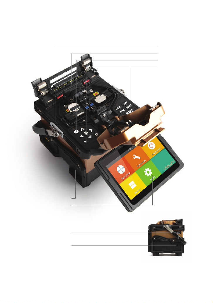
Heat oven
USB Type-C port
DIN Port
Power supply connector
Display
Power supply / Battery
Loop
On / Off button
Control buttons
Splicer overview

Chapter 2 Installation 18
Insert the battery into the power unit dock until it clicks into place.
Insert
Release button
Take out the battery
Step 1 Step 2
Power supply
Battery
Switch off the splicer. Press the [Release] button at the side of the splicer and take
out the battery from the splicer.
Charge the battery
Connect the battery charger to the battery.
Charging progress is indicated by five lit LEDs continuously sweeping from 20% to
100% on the battery indicator (see below).
As charging proceeds, one LED is lit when 20% charged. When it’s fully charged,
all five LEDs are lit (i.e. 100%).

Chapter 2 Installation 19
Note: Check and make sure the remaining battery capacity is 20% or greater
before splicing. If the battery capacity is less than 20%, please use AC / DC
adapter to power the splicer. Heat will be generated during the charging
process. Do not stack the battery on top of AC / DC adapter while charging.
How to check remaining battery capacity
You have two ways to check remaining battery capacity.
•If the battery is connected to the splicer, its charging level appears on the top
right corner of the monitor.
•If the battery is detached from the splicer, press “PUSH” button on the battery.
Then the battery capacity will be indicated by LEDs as shown below:
Battery refresh
In order to prevent the aging effect of the battery, the battery needs to be refreshed
periodically. Turn the splicer on and discharging until it consumes all the battery
capacity and the splicer turns off automatically. Fully recharge the battery and redo
discharging.
20
Basic Operation
Turning on the splicer
Press [Power] key on the operation panel, and wait the splicer to be turned on and
move to Workbench page.
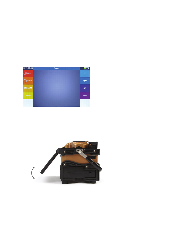
Adjusting the monitor position
Users can adjust the monitor position by moving it with a desired angle in purpose
of operation convenience.
3
Table of contents
Other INNO Industrial Electrical manuals

Popular Industrial Electrical manuals by other brands

Siemens
Siemens 8MF1000-2H Series operating instructions

Lucent Technologies
Lucent Technologies LINEAGE 2000 Evolutionary Control System Battery... product manual

Murata
Murata GRM0225C1E5R2DA03 Series Reference sheet

Siemens
Siemens 3VT9200-3MJ00 operating instructions

Murata
Murata GQM1555C2A470JB01 Series Reference sheet

Murata
Murata GRM0335C1E5R0CA01 Series Reference sheet


Murata
Murata GRM0225C1E7R6WDAE Series Reference sheet

Murata
Murata GRM32RR71E225KA01 Series Reference sheet

Murata
Murata GRM32NR61A226KE19 Series Reference sheet

ABB
ABB PCS100 AVC-40-1B Accessories assembly instructions

Fagor
Fagor S2 installation manual

Murata
Murata GRM21BR71E154KA01 Series Reference sheet