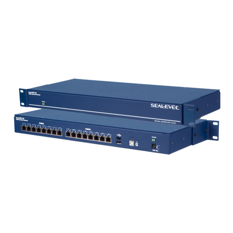
Innoband HomePlug AV Wireless N Starter Kit User manual

HomePlug AV Wireless N
Starter Kit
User Manual
Issue1.0
Sept 3rd, 2009

User Manual
INNOBAND HOMEPLUG AV WIRELESS NSTARTER KIT
Information in this document is subject to change without notice and does not represent a commitment on
the part of Innoband Technologies, Inc. The software described in this document is furnished under a
license agreement and may be used or copied only in accordance with the terms of the license
agreement. It is against the law to copy the software on any other medium except as specifically allowed
in the license agreement. The licensee may make one copy of the software for backup purposes. No part
of this manual may be reproduced or transmitted in any form or by any means, electronic or mechanical,
including photocopying and recording, for any purpose without the written permission of Innoband
Technologies, Inc.
All contents are Copyright © 2009 Innoband Technologies, Inc. All rights reserved.
Manual Version 1.0
September 2009
Innoband is a trademark of Innoband Technologies, Inc. The trademarks, logos and service marks
(“Marks”) displayed on this manual are the property of Innoband or other third parties. Users are not
permitted to use these Marks without the prior written consent of Innoband or such third party that may
own the Mark. IBM is a registered trademark of International Business Machines Corporation. Intel and
Pentium are registered trademarks of Intel Corporation. Microsoft, MS-DOS, Windows, and the Windows
logo are registered trademarks of Microsoft Corporation. All other products are trademarks or registered
trademarks of their respective owners.
2

Table of Contents
USER MANUAL..........................................................................................................................................................2
1PRODUCT INTRODUCTION.........................................................................................................................5
NO SWEAT TO SET UP AN IN-HOME NETWORK ............................................................................................................5
EXTENDED WIRELESS COVERAGE .............................................................................................................................5
SMOOTH TRAFFIC AND PRIORITIZATION.....................................................................................................................5
IMMUNE TO NOISE AND INTERVENTION......................................................................................................................5
FEATURES..................................................................................................................................................................6
QUALITY OF SERVICE CONTROL................................................................................................................................6
WIRELESS LAN.........................................................................................................................................................6
SPECIFICATIONS.........................................................................................................................................................7
2INSTALLING THE ADAPTER.......................................................................................................................8
DEVICE OVERVIEW....................................................................................................................................................9
HomePlug AV 200P-I1.........................................................................................................................................9
HomePlug AV Wireless-N 210P-I1....................................................................................................................10
HARDWARE INSTALLATION .....................................................................................................................................11
Installing a different Clip to the Socket..............................................................................................................11
Installing the HomePlug AV 200P-I1 / 210P-I1 ................................................................................................12
QUICK START (SETUP POWERLINE NETWORK)........................................................................................................13
Push Button usage..............................................................................................................................................13
Application Scenarios........................................................................................................................................13
Powerline Network Illustration..........................................................................................................................15
3CONFIGURATION.........................................................................................................................................16
UNDERSTANDING THE CD CONTENT .......................................................................................................................16
Microsoft .NET Framework 2.0 Installation......................................................................................................18
HomePlug AV 200P-I1 Utility Installation........................................................................................................19
UNDERSTANDING THE HOMEPLUG AV 200P-I1 UTILITY........................................................................................20
Main Tab............................................................................................................................................................20
Procedure to Setup Password to a HomePlug Device:.................................................................................................... 22
Procedure to add New HomePlug Device to a Powerline Network:...............................................................................22
Privacy Tab........................................................................................................................................................23
Diagnostics Tab .................................................................................................................................................25
QoS Tab .............................................................................................................................................................26
Firmware Download Tab...................................................................................................................................27
About Tab...........................................................................................................................................................28
UNDERSTANDING THE HOMEPLUG AV WIRELESS N210P-I1 WEB INTERFACE ......................................................29
Network Configuration ......................................................................................................................................30
Configuring PC in Windows Vista..................................................................................................................................30
Configuring PC in Windows XP.....................................................................................................................................32
Configuring PC in Windows 2000.................................................................................................................................. 33
Configuring PC in Windows 95/98/Me...........................................................................................................................34
Configuring PC in Windows NT4.0................................................................................................................................35
Configuring 210P-I1 with your Web Browser ...................................................................................................36
HomePlug AV Wireless N 210P-I1 Factory Default Settings:........................................................................................36
Logging on to the HomePlug AV Wireless N 210P-I1 Web Interface:...........................................................................36
Navigating through the HomePlug AV Wireless N 210P-I1 Web Interface:..................................................................36
Status .........................................................................................................................................................................37
Statistic...................................................................................................................................................................... 38
Internet Setting .......................................................................................................................................................... 39
LAN......................................................................................................................................................................39
3

DHCP Type: Server (DHCP Server)....................................................................................................................40
Wireless Settings ....................................................................................................................................................... 41
Basic Wireless Settings ........................................................................................................................................ 41
Wireless Distribution System (WDS)................................................................................................................... 42
Wireless Security/Encryption Settings.......................................................................................................................44
Access Policy .......................................................................................................................................................44
Security Modes..................................................................................................................................................... 45
Advanced Wireless Settings.................................................................................................................................47
Wi-Fi Protected Setup .......................................................................................................................................... 48
Station List ........................................................................................................................................................... 49
Power Line Settings................................................................................................................................................... 50
Status
....................................................................................................................................................................50
Privacy
..................................................................................................................................................................51
QoS.......................................................................................................................................................................52
Administration........................................................................................................................................................... 55
System Management ............................................................................................................................................55
Firmware Upgrade................................................................................................................................................ 55
Settings Management ........................................................................................................................................... 57
4TROUBLESHOOTING ..................................................................................................................................58
APPENDIX A - WARRANTIES..............................................................................................................................60
APPENDIX B - REGULATION ..............................................................................................................................62
APPENDIX C – CONTACT INFORMATION......................................................................................................63
4

1 Product Introduction
Compliant with the latest HomePlug AV standards, which support data speeds of up to 200Mbps,
Innoband HomePlug AV Wireless N Starter Kit is a bundle that includes Innoband’s non-wireless
HomePlug, the 200P-I1. Together, the 200P-I1 and the 210P-I1 can be used to bridge Ethernet
devices such as modems, routers, PCs, set-top-boxes, and game consoles, allowing users to share
network access via existing in-home power cabling. What's unique is that the device has an extra
built-in 02.11n Access Point, enabling users to enjoy mobility, high-speed wireless connection and
better coverage with no more dead zones. Just plug the 210P-I1 into any wall power socket and you
can easily set up a secure wireless network by pressing the Wi-Fi Protected Setup (WPS) button.
Thus, the adapter can extend your wireless coverage through powerlines for multimedia applications
such as online games, IPTV and audio streaming from room to room.
No sweat to set up an in-home network
Innoband HomePlug AV Wireless N Starter Kit does not require the time and money needed to
install expensive Ethernet cables throughout your house in order to share your home network. Nor
does it require any drilling. Just one touch of the “Sync” button to install the bridge utility and your
high-speed network is ready. It’s as easy as simply plugging in your networking devices and using
the electrical wiring in your home.
Extended Wireless Coverage
With an integrated Draft-802.11n Wireless Access Point, the wireless unit, the 210P-I1, can bridge
wireless connections of up to 6 times the speed and 3 times the wireless coverage of an 802.11b/g
network device. It supports a data rates up to 300Mbps and is also compatible with 802.11b/g
equipment. The Wireless Protected Access (WPA-PSK / WPA2-PSK) and Wireless Encryption
Protocol (WEP) features enhance the level of transmission security and access control over Wireless
LAN. The device is also pre-configured with the Wi-Fi Protected Setup (WPS) standard, allowing
users to establish a secure wireless network by simply pushing a button.
Smooth traffic and prioritization
Quality of Service control guarantees the transmission quality by automatically prioritizing data.
200P-I1 and 210P-I1 automatically recognizes the bandwidth needs of voice and video applications.
QoS prioritizes the data to guarantee optimal transmission quality. TV and video images are received
and displayed with absolute smoothness. QoS also guarantees clear, instant transmission of voice
data, even when other applications are running on the network at the same time. QoS makes your
network a pleasure to use.
Immune to noise and intervention
Unlike others, the device supports superior and noise-immune data transmission over in-home
electrical powerlines. Even at the moment your family turns on an electronic device or turns off a
light, you won’t experience any interruption to latency-sensitive applications such as multimedia or
video being shared with your family in another room.
5

Features
• Provides physical layer data rate of up to 200Mbps over existing in-home powerlines
• Extended wireless coverage of up to 3 times the range of 802.11g products
• Pre-configured WPS (Wi-Fi Protected Setup)
• Auto channel select
• Utilizes powerline technology that takes advantage of the unused bandwidth of the electrical
wiring in your home
• Utilizes Quality of Service (QoS) control
• Supports Triple Play applications such as IPTV, VoIP and high-speed Internet access
• Supports 10/100 Base-T Ethernet
• Compliant with the HomePlug Powerline Alliance industry specifications
• Ideal for residential users
Quality of Service Control
• Enhancements: contention-free access, four-level priority based contention access, and multi-
segment bursting
• ToS, CoS and IP Port Number Packet Classifiers
• Supports IGMP managed multicast sessions
• IGMP snooping with multicast to multiple unicast support in CSMA
• QoS classification for quasi-error-free delivery - VLAN priority field, ToS Field
• Enhanced IPv4/IGMPv1-3 snooping support
• Supports IPv6 and MLDv1-2 snooping
Wireless LAN
• Compliant with IEEE 802.11n, 802.11g and 802.11b standards
• 2.4 GHz-2.484 GHz frequency range
• Auto channel select
• Up to 150Mbps wireless operation rate
• Pre-configured WPS (Wi-Fi Protected Setup)
• 64/128 bits WEP supported for encryption
• Wireless Security with WEP/WPA-PSK/WPA2-PSK support
6

Specifications
Protocol TDMA, CSMA/CA
Standard Ethernet specification: IEEE 802.3, IEEE 802.3x, IEEE 802.3u, Auto
MDI/MDIX
Powerline Up to 200Mbps transfer rate
Modulation Supports OFDM - 1155 carriers,1024 / 256/64QAM, QPSK, BPSK and ROBO
Frequency Band 2MHz ~ 30MHz
Security 128-bit AES Link Encryption with key management for secure powerline
communications.
Encryption: NMK (Network Membership Key) used to authenticate/access
Rotating NEK (Network Encryption Key)
Operating System Windows 98_SE / Me / 2000 /XP/ Vista
Other 10/100 Base-T Ethernet devices
Power Supplier Input: 100~240V AC, 50~60Hz
Protection: OCP, OVP, SCP
Operating Temperature
/ Humidity
Operating temperature: 0 ~ 40°C
Storage temperature: -20 ~ 70°C
Humidity: 20~95% non-condensing
Physical Interface 200P-I1
AC power plug
RJ-45 compatible (10/100 Base-T
Ethernet)
Sync button
Reset button
LED display:
DET
POWER
PLC
ETH
210P-I1
1 antenna
AC power plug
RJ-45 compatible (10/100 Base-T
Ethernet)
WPS button
Sync button
Reset button
LED display:
WLAN
POWER
PLC
ETH
Dimension (W, D, H): 4.42” x 3.05” x 1.75”
(112.4mm x 77.4mm x 45mm) (W, D, H): 4.42” x 3.05” x 2.12”
(112.4mm x 77.4mm x 53mm)
Power Saving
(200P-I1 only) Reduce power consumption by at least 60% during power saving mode.
7

2Installing the Adapter
In addition to this document, your package should arrive containing the following:
A non-wireless HomePlug AV 200P1-I1
A wireless N HomePlug AV 210P-I1
Two Ethernet cables ( RJ-45 )
A CD that contains User Manual and 200P-I1 utility
1 x 200P-I1
HomePlug AV device
1 x 210P-I1
HomePlug AV Wireless N device
2 x Ethernet cables (RJ-45)
CD contents:
- User manual
- 200P-I1 utility
8

Device Overview
HomePlug AV 200P-I1
The Description of each labeled part is described in the table below:
1.0 DET LED Blink when detect the presence of other HomePlug 1.0 devices that
have the transmission rate of 14 or 85 Mbps.
Note: Due to the incompatibility of HomePlug AV 200 with
HomePlug 1.0 devices, the presence of the HomePlug 1.0 devices
within the powerline network will thus reduce the performance of
your powerline network.
Power LED Lit when the power is on.
PLC (Powerline Link/Act)
LED
Lit when a network has been established.
Blink after Sync button is pushed (see Sync button description below)
Blink quickly when powerline data is transmitted or received.
ETH (Ethernet Link/Act) LED Lit when an Ethernet data signal is transmitted or received.
Sync Button Used to establish a LAN network with other powerline devices.
Press this button for 1~3 second(s) and release it to set device into
powerline Sync state.
Reset Button Press this button for 1~3 second(s) to restore the device configuration
to factory default.
Ethernet Port Connect the HomePlug AV device with an Ethernet device (e.g. PC or
modem router) with the Ethernet cable included.
Power Plug Plug into an electric socket to draw power and to form a powerline
network with other HomePlug AV devices.
Ethernet Port
1.0 DET LED
POWER LED
PLC LED
ETH LED
SYNC button
RESET button
Power Plug
9

HomePlug AV Wireless-N 210P-I1
The Description of each labeled part is described in the table below:
WLAN LED Lit green when the wireless function is enabled.
Blink when data is transmitted or received via WLAN.
Blink quickly when WPS is activated.
Power LED Lit when the power is on.
PLC (Powerline Link/Act)
LED
Lit when the powerline sync is established.
Blink after Sync button is pushed (see Sync button description below)
Blink quickly when data is transmitted or received via powerline.
ETH (Ethernet Link/Act) LED Lit when connected to an Ethernet device.
Blink when data is transmitted or received via Ethernet port.
WPS Button Push this button to trigger Wi-Fi Protected Setup function.
Sync Button Used to establish a LAN network with other powerline devices.
Press this button for 1~3 second(s) and release it to set device into
powerline Sync state.
Reset Button Press this button for 1~3 second(s) to reset the device to factory
default settings.
Ethernet Port Connect the HomePlug AV device with an Ethernet device (e.g.
computer, router, hub/switch, IP pone, IPTV set-top-box, gaming
consoles), using the RJ-45 Ethernet cable included.
Power Plug Plug into an AC outlet for power supply and to build a powerline
network with other HomePlug AV devices.
Clip Socket Install the clip into this socket.
Note: Please DO NOT remove or disassemble the socket clip
frequently as this may cause serious damage on your HomePlug
AV device.
10

Hardware Installation
Installing a different Clip to the Socket
Refer to the following diagrams and instructions to install the clip with Innoband HomePlug
AV 210P-I1:
Example 1: EU clip
Example 2: UK clip
11

Installing the HomePlug AV 200P-I1 / 210P-I1
Refer to the following steps:
1. Connect an Ethernet cable to the Ethernet port of the HomePlug AV, and then plug
either 200P-I1/210P-I1 into a power socket (sample shown is 210P-I1).
2. Then connect 200P-I1/210P-I1 to a laptop, modem, router or a set-top-box.
3. Create a secure network by simply pushing the SYNC button for 1~3 seconds.
4. Repeat the first three steps with the other HomePlug AV device.
Note: Plug/socket, power cable and input voltage/frequency may vary from
country to country.
12

Quick Start (Setup Powerline Network)
Push Button usage
Sync Button is used to add a HomePlug AV device to a Powerline network or enable it to join a network
by pressing the Sync Button of the device to turn it into Broadcast state or Join state.
There are 3 types of Sync Button trigger states:
1.
Broadcast State:
Enable
Innoband HomePlug AV 200P-I1/210P-I1
device to provide
information for another
HomePlug AV device to join its powerline network group (works even
if it is the only device existing within the network group).
2.
Join State:
This allows an ungrouped
Innoband HomePlug AV 200P-I1/210P-I1
device to
join an existing powerline network group.
3.
Ungroup State:
Press the Sync Button for more than
10 seconds
to detach the device
from its network group.
Application Scenarios
Scenario 1: An Innoband HomePlug AV device A wants to form a network group with another
Innoband HomePlug AV device B
You can assign whichever device (A or B) to be in the Broadcast State and the other in the Join State.
Example:
1. Press the Sync Button of device A for 1~3 seconds to turn it into Broadcast State, you
should find the Power LED blinks steadily signifying it is in Broadcast state.
2. Press the Sync Button of device B for 1~3 seconds to turn it into Join State, you should
find the Power LED blinks steadily signifying it is in Join state.
3.
Wait for both devices to boot again (all LEDs will turn off and on) and when the PLC LEDs
of both devices lit steadily
, you will now have these devices being in the same network
group.
Applicable to 200P-I1 only: Once the device is plugged into the electric socket, connect it with an
Ethernet cable within 60 seconds to prevent the device from going into Power Saving mode.
13

Scenario 2: An Innoband HomePlug AV device wants to join an existing network group BC
Device A wants to join a network group “BC” currently consisting of device B and device C. Any devices
within the “BC” group can become the “Broadcast State” and device A will be the “Join State”.
Example:
1. Press the Sync Button of device A for more than 10 seconds to make sure that it is detached
completely from any possible network group.
2. Press the Sync Button of device B or C of the BC network group for 1~3 seconds to turn it into
Broadcast State, you should find the Power LED blinks steadily signifying it is in Broadcast
state.
3. Press the Sync Button of device A for 1~3 seconds to turn it into Join State, you should find
the Power LED blinks steadily signifying it is in Join state.
4. Wait for the devices to boot again and when the PLC LEDs of both devices lit steadily, you will
now have device A joined with the BC network group.
Applicable to 200P-I1 only: Once the device is plugged into the electric socket, connect it with an
Ethernet cable within 60 seconds to prevent the device from going into Power Saving mode.
Scenario 3: An Innoband HomePlug AV device A of network group AD wants to join an existing network
group BC
For a device which already belongs to a network group is to join with a different network group, that device
has to be ungrouped from its current attached group first.
Example:
1. Press the Sync Button of device A for more than 10 seconds to ungroup it from network group AD.
2. Then press the Sync Button of device (B or C) of network group BC for 1~3 seconds to turn it to
Broadcast State, you should find the Power LED blinks steadily signifying it is in Broadcast state.
3. Press the Sync Button of device A again for 1~3 seconds to turn it to Join State, you should find
the Power LED blinks steadily signifying it is in Join state.
4. Wait for the Sync LED of both devices A and (B or C) lit steadily. Now you will have device A join
the network group BC.
Applicable to 200P-I1 only: Once the device is plugged into the electric socket, connect it with an
Ethernet cable within 60 seconds to prevent the device from going into Power Saving mode.
14

Powerline Network Illustration
15

3Configuration
Understanding the CD Content
1. Place the HomePlug AV Wireless N Starter Kit auto-installation CD into your CD/DVD ROM
drive.
2. When the following splash screen appears, click on 200P-I1 Utility for Easy Installation.
16

3. The following splash screen would appear:
4. Click on Step 1: Install Microsoft .NET Framework 2.0 to install this program first before
installing Innoband 200P-I1 Utility.
Note: If you are running Windows Vista or already have installed Microsoft .NET
Framework 2.0, simply click on Step2: Install the Utility.
17

Microsoft .NET Framework 2.0 Installation
1. After clicking on Step1: Install Microsoft .NET
Framework 2.0 in the splash screen, the following
pop-up window would appear.
2. Click on the Yes button.
3. Click on Next to proceed with the installation.
4. Check the “I accept the terms of the
License Agreement” checkbox to proceed.
5. Click on Install button to start the installation.
6. When the installation is completed, click on
Finish to exit.
18

HomePlug AV 200P-I1 Utility Installation
1. After clicking on Step 2: Install HomePlug AV
200P-I1 Utility, the following installation wizard
will appear.
2. Click on Next to proceed with the installation.
3. Click on Browse to define a location other than
the default location.
4. Select whether to install HomePlug AV 200P-I1
Utility only for yourself or for all the users who
share your PC.
5. Click on Next to proceed with the installation.
6. Click on Next to confirm and start the
installation.
7. When the installation is completed, click on
Close.
19

8. A shortcut will appear on the desktop once the HomePlug AV 200P-I1 Utility
Setup Wizard is installed. You can start the HomePlug AV 200P-I1 Utility by
double clicking on the shortcut, or go through Start ÆAll Programs Æ
HomePlug AV 200P-I1 Utility ÆHomePlug AV 200P-I1.
Understanding the HomePlug AV 200P-I1 Utility
The HomePlug AV 200P-I1 Utility window consists of 6 tabs. They are: Main, Privacy, Diagnostics,
QoS, Firmware Download, and About.
Main Tab
This tab shows details of locally and remotely connected device(s). It also allows user to customize their
powerline network.
Local Device(s) on your computer panel: Shows all local HomePlug devices connected to the
computer’s NIC (Network Interface Card).
Connected to HomePlug AV Device status area: Indicates that your PC is connected to the device
highlighted on the left panel. The status area displays a HomePlug Adapter NOT DETECTED
message when no local HomePlug device is discovered.
Connect button: Click to select a local device when multiple devices are listed on the left panel.
Note: the utility automatically scans the powerline periodically for other newly connected
HomePlug devices the moment a HomePlug adapter is connected to the local device.
20
This manual suits for next models
2
Table of contents
