Innomed Medical TOP-X 100NR User manual
TOP-X
HIGH-FREQUENCY
X-RAY GENERATOR
MODEL: TOP-X 100NR
USER MANUAL
Manufacturer:
Innomed Medical Inc.
1146 Budapest
Szabó József u. 12.
Hun ary
Tel: (36-1) 460-9200
Fax: (36-1) 460-9222
www.innomed.hu
D-0603-EN/F
28.04.2010.

TOP-X100NR USER MANUAL Innomed Medical Inc.
2
Table of contents
1. Introduction ........................................................................................................................ 5
1.1 General ....................................................................................................................... 5
1.2 Control panel .............................................................................................................. 6
2. Turning the generator on and off........................................................................................ 8
3. Load limits, writing a log file............................................................................................. 9
4. Errors................................................................................................................................ 11
4.1 Error display............................................................................................................. 11
4.2 Error acknowledgement ........................................................................................... 11
4.3 Types of errors.......................................................................................................... 11
4.3.1 Limit control..................................................................................................... 11
4.3.2 Warnings .......................................................................................................... 11
4.3.3 X-Ray interruption, inhibition.......................................................................... 12
4.3.4 Safe mode......................................................................................................... 12
4.3.5 Turn off ............................................................................................................ 13
4.4 Log file ..................................................................................................................... 13
4.5 Service contact ......................................................................................................... 13
4.6 Basic errors............................................................................................................... 13
5. Anatomical program mode............................................................................................... 15
6. Automatic exposure control (AEC).................................................................................. 17
6.1 The AEC operating mode......................................................................................... 17
6.2 AEC operating mode setting possibilities ................................................................ 17
6.2.1 DENSITY – density correction ........................................................................ 18
6.2.2 SCREEN – screen selection ............................................................................. 18
6.3 Verifying the exact operation of the AEC................................................................ 19
7. Parameter setting in manual operating mode ................................................................... 20
7.1 Radiation parameter setting...................................................................................... 21
7.1.1 Setting exposure X-ray tube voltage (kV)........................................................ 21
7.1.2 Three-point mode, mA / ms setting.................................................................. 21
7.1.3 mAs mode (or two-point mode) ....................................................................... 22
7.1.4 PATIENT – Patient size................................................................................... 22
7.2 Examination device, X-ray tube and focal spot selection ........................................ 23
7.2.1 TECHNIQUE – examination device................................................................ 23
7.2.2 BUCKY – grid symbol..................................................................................... 23
7.2.3 HS – high-speed ............................................................................................... 23
7.2.4 FOCUS – X-ray tube focal spot ....................................................................... 24
7.2.5 Automatic selection of large focal spot and high-speed rotation ..................... 24
7.2.6 TUBE – X-ray tube .......................................................................................... 25
7.3 RADIATION - Preparation, exposure...................................................................... 25
8. Fluoroscopic mode ........................................................................................................... 26
8.1 Controls on the fluoroscopic controller.................................................................... 26
8.2 Power on................................................................................................................... 26
8.3 Exposure parameters ................................................................................................ 28
8.3.1 Exposure x-ray tube voltage (kV) setting......................................................... 28
8.3.2 mAs mode (or two-point mode) ....................................................................... 28
8.3.3 AEC dominant field selection .......................................................................... 28

TOP-X100NR USER MANUAL Innomed Medical Inc.
3
8.3.4 Selecting anatomical program .......................................................................... 29
8.4 Fluoroscopic parameter setting ................................................................................ 30
8.4.1 Fluoroscopic x-ray tube voltage (kV) setting................................................... 30
8.4.2 Fluoroscopic x-ray anode current (mA) setting................................................ 30
8.4.3 Fluoroscopic time............................................................................................. 30
8.4.4 Zoom ................................................................................................................ 31
8.4.5 Video modes..................................................................................................... 31
8.4.6 Impulse fluoroscopic operating mode .............................................................. 32
8.4.7 Automatic brightness setting (ABS)................................................................. 33
8.4.8 Digital image storage from fluoroscopic operating mode................................ 34
8.5 Fluoroscopic parameter setting on the control panel................................................ 35
8.5.1 Displaying fluoroscopic parameters on the control panel ................................ 35
8.5.2 Setting fluoroscopy x-ray voltage (kV) ............................................................ 36
8.5.3 Setting fluoroscopy x-ray current (mA) ........................................................... 36
8.5.4 Fluoroscopy time.............................................................................................. 36
8.5.5 Zoom ................................................................................................................ 36
8.5.6 Video modes..................................................................................................... 37
8.5.7 Impulse fluoroscopy operating mode ............................................................... 37
8.5.8 Automatic brightness setting (ABS)................................................................. 38
8.5.9 Digital image storage from fluoroscopy operating mode ................................. 38
9. Cleaning and maintenance................................................................................................ 40
10. Technical data............................................................................................................... 41
11. Disposal of Old Electrical & Electronic Equipment .................................................... 46

TOP-X100NR USER MANUAL Innomed Medical Inc.
4
WARNING!
Innomed Medical Inc. states the following information according to operative European
norms and related international standards.
Extensive preparedness in the field of X-ray diagnostics is
required for the operation of the
generator. There is dangerous voltage inside the generator and in the high-
voltage cables
connected to the X-
ray tubes, even after it has been turned off. During the operation of the
generator the X-ray source generates X-
rays, so the device may only be used in a work area
prepared according to X-
ray safety regulations. During operation take all necessary
precautions to protect the patient, yourself and the environment from the harmful effects of
the generated X-ray radiation.
During the operation of the generator when selecting the applied examination, treatment or
intervention, for the patient’s protection and the accuracy of the diagnostic results, take into
consideration the generated X-ray radiation’s physical, chemica
l and physiological effects,
their treatments, interventions and efficiency, and the effects and possible risks on the
equipment.
The generator must be installed, checked and maintained according to the following
document and references:
R-2622
TOP-X 100NR
HIGH FREQUENCY X-RAY GENERATORS
TECHNICAL MANUAL AND INSTALLATION GUIDE
Only personnel properly trained in X-
ray technology may perform any servicing on the
generator.
During normal operation the generator does not emit any environmentally dangerous
substances. The oil in the generator’s high-
voltage transformer is dangerous to the
environment so its disposal must be according to the environmental regulations in effect.
When rolling out the generator or its parts the operative environmental regulations
must be
followed.
Not complying with the user manual and the installation related regulations might result in
the generator not fulfilling manufacturer specified specifications and endanger the operator,
the patient or the environment. The manufacturer i
s not responsible for results of not
complying with the regulations.
Portable and mobile RF communication equipment may interfere with generator operation.
The generator requires special precautions regarding EMC. Installation must be performed
according to the EMC information in the technical data and installation manual.
For the safety of your patient and the reliable operation of the device please read the entire
manual to become acquainted with it.

TOP-X100NR USER MANUAL Innomed Medical Inc.
5
1. Introduction
We would like to welcome your decision to purchase the TOP-X 100NR high-
frequency X-ray generator. We wish you success with its application!
This document contains all the information necessary for the operation of the TOP-X
100NR high-frequency X-ray generator.
1.1 General
With the permanently installed devices connected at installation, generator TOP-X
100NR is capable of making diagnostic X-ray exposures and fluoroscopy on human
bodies or animals, in a hospital or a surgery. Exposure parameter limits can be found
in chapter 10.
Operators of this equipment should be properly qualified for X-ray diagnostics,
especially for the harmful properties of X-ray radiation. Manufacturer of the X-ray
equipment is not responsible for any harms resulting from wrong X-ray parameter
setting.
The main feature of the TOP-X 100NR X-ray generator is the easy operation. The
configuration containing the anatomical programs can contain up to 1700 pre-
programmed automatic recording settings. The settings are grouped by body parts;
selection of a body part menu allows the selection of sub body parts. If required the
settings can be modified manually (3-point: kV, mA, time; and 2-point: kV, mAs).
The TOP-X 100NR X-ray generator has the following main parts:
• control panel
• power unit, which contains the high-voltage transformer, the power electronics, the
generator controller and the device interface
X-ray diagnostic equipments are connected to the generator: X-ray tube, collimator,
examination devices, etc. These are already connected during installation according
to the installation manual; other devices do not have to be connected during
operation.
In this manual we will detail the control panel’s operation; the power unit does not
contain any controls.
The appearance of the control panel (NRDTC) can be the following:
• Plastic frame, table-top version
• Glass frame with stainless-steel stand and exposure switch holder
The front panels of the above versions are identical, their operation are the same.
TOP-X100NR USER MANUAL Innomed Medical Inc.
6
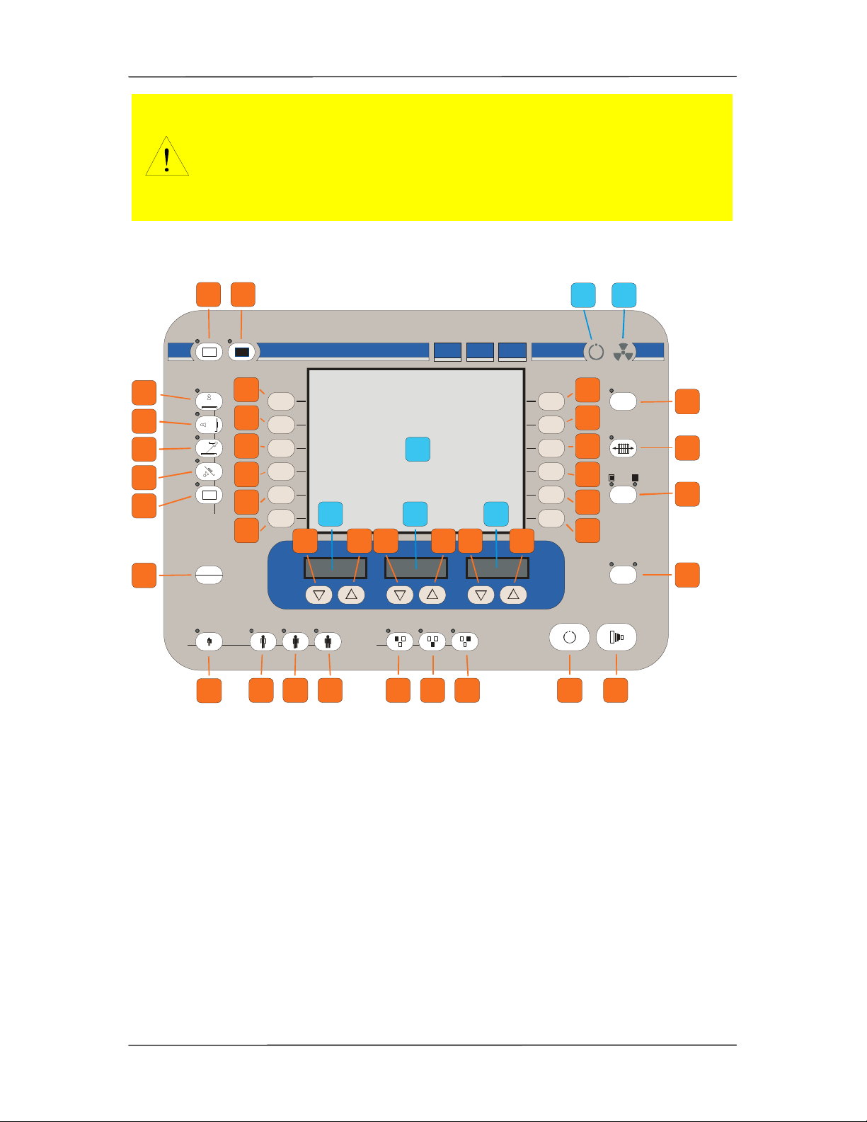
1.2 Control panel
PREP EXP
TOP-X 100 NR - INNOMED MEDICAL
sec
mA / mAs
kV
WARNING ! This X-ra unit ma be dangerous to patient and operator unless safe exposure factors and operating instructions are observed.
FOCUS
HS
MODE
mAs
mA / sec
APR
SET
AUX
OFFON
1 2
3
4
5
6
7
8
9
10
11
12
13
14
15
16
17
18
19
20
21 22 23 24 25 26 27 28 29
30
31
32
33
34 35 36 37 38 39
A
B C D
E F
In the rest of the manual the above image is referenced by the button and display
identifying number or letter. For example (8), (B).
Make sure the generator and its parts (control panel) are always
clean. For the proper cooling of the power unit the vent openings
must be open at all times. Do not cover it with a tablecloth or place
other items on it even temporarily. Make sure no liquid or foreign
objects – especially metal – get inside the generator. Cleaning the
generator is detailed in the Cleaning and maintenance section.
TOP-X100NR USER MANUAL Innomed Medical Inc.
7
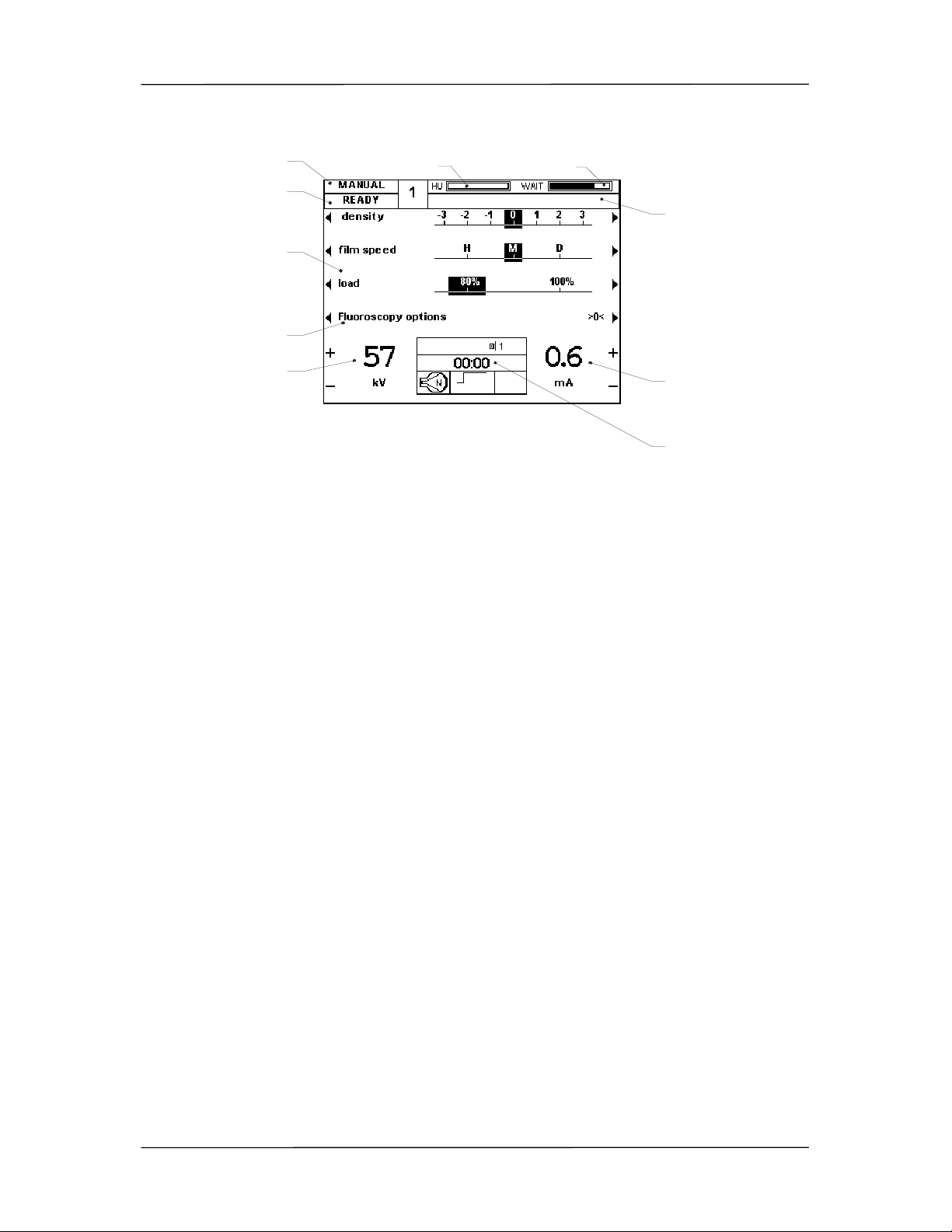
LCD display layout
Manual parameter setting
Ready for use
Other settings
Other fluoro settings
Fluoroscopic X-Ray
tube voltage
Heat being
stored in X-Ray tube Cooling time
Fluorocsopic X-Ray tube
current
Actual fluoro settings
Error / information
display

TOP-X100NR USER MANUAL Innomed Medical Inc.
8
2. Turning the generator on and off
Turn the generator on with the ON button (1) and off with the OFF button (2). The
LED above the ON button indicates when the generator is on, and the LED above
the OFF button indicates when it is off, but the input mains presented.
When turning the generator on a process starts during which the control panel, the
X-ray controller, and the generator controlled parts are placed under voltage. As a
first step the generator performs a self-test procedure.
Parameters may be set after the default settings (80kV, 100mA, 100ms) appear on
the LED displays (B, C, D).
Exposure can be started when the main contactor is on and READY appears on the
panel LCD (A).

TOP-X100NR USER MANUAL Innomed Medical Inc.
9
3. Load limits, writing a log file
The generator takes the load-limit of the parts into consideration in all operating
modes and does not allow the use of settings that can damage the generator or the
X-ray tube.
The generator considers the following limits:
• The maximum allowed anode voltage (kV) value of the generator.
• The maximum allowed anode current (mA) value of the generator.
• The maximum allowed power (kW) value of the generator.
• The maximum allowed current – time product (mAs) value of the generator.
• The maximum allowed anode current (mA) value of the X-ray tube for both focal
spots, considering anode rotation speed.
• The maximum allowed anode voltage (kV) of the X-ray tube.
• The maximum allowed power (kW) of the X-ray tube for both focal spots,
considering the anode rotation speed and the set exposure time.
• The input heat from rotation and from exposures, and the cooling period,
considering the thermal energy in the anode and in the housing. This is calculated
exactly even if the generator is turned off and turned back on much later. This is
called the “heat unit (HU) calculation”.
• The cooling period of the “track” – the anode’s most loaded part during exposure.
This is called ”wait time”.
To prevent overload, the HU value is always displayed on the top right corner of the
control panel’s LCD (A). It indicates the calculated amount of heat that would be
stored in the tube, as a percentage of the total load-limit, if the exposure with the
currently set parameters was made. As the tube cools, this value decreases.
A slowly decreasing line will appear after every exposure next to the HU value with
the word WAIT. This indicates the cooling period of the anode track.
Do not perform exposure as long as the HU value is over 100%,
because it will overload the tube!
Do not perform exposure until the word WAIT disappears, because
it will overload the tube!

TOP-X100NR USER MANUAL Innomed Medical Inc.
10
The generator logs all exposures. All exposure data (date, time, set / measured
values) are stored. Three logs are created:
Normal exposures:
This contains all perfect exposures. Its capacity is approximately 600 exposures.
Faulty exposures:
This contains the data of exposures that end with fault-message. Its capacity is
approximately 300 exposures.
Overloaded exposures:
This contains the exposures that had HU value over 100% at the moment of
exposure, or the WAIT time did not reach zero. Its capacity is approximately 300
exposures.
A PC based service program can be used to view the logs. If any of the logs are full,
the oldest exposure’s data is deleted, overwritten with the newest ones.
For both of the above cases exposure is not disabled.
It is the operator’s responsibility to decide whether to make
exposure contrary to the warning. The generator records
exposures made with overloading in a separate log-file!
TOP-X100NR USER MANUAL Innomed Medical Inc.
11
4. Errors
4.1 Error display
In case of an error a text is shown on the top right part of the console display to
inform about the type of the error and a code which identifies the error more precise
for a qualified person.
If the operational state of the generator changes the top left script of "READY" shows
the new state.
4.2 Error acknowledgement
In case of any error it can be cleared by pushing any button on the console or on the
fluoro remote controller. In case of an error causing “safe mode”, the error display
can be cleared, but the exposure remains disabled. Another exposition can only be
made after turning the generator off and on again.
4.3 Types of errors
The errors are grouped by their fatality.
The "READY" script on the console display means that no error happened disabling
the generator operation, so the generator is ready for use.
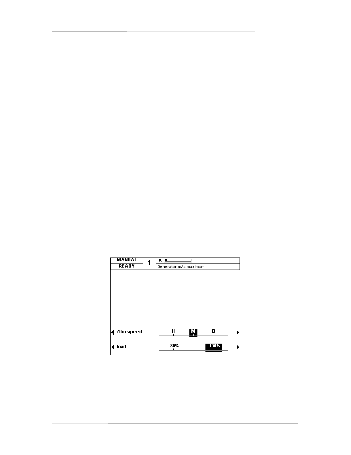
4.3.1 Limit control
The warnings displayed when reaching the load limits of the X-Ray tube or the
generator are only for information. E.g.: Reaching the current-time product (mAs)
limit of the generator:
The generator remains ready for use, the "READY" script does not change.
4.3.2 Warnings
Warnings are errors detected by the generator that do not influence the operation
from the standpoint of the user, but are logged. E.g.: Pushing an exposure button
that is unusable according to the current configuration.

TOP-X100NR USER MANUAL Innomed Medical Inc.
12
The "READY" script changes to "WARNING".
4.3.3 X-Ray interruption, inhibition
These error disable the exposure and preparation. In case of such an error the
exposure in progress is interrupted. Mostly caused by a system state that is
dangerous to the generator or the connected equipment or makes the further use
impossible. E.g.: No current on the selected filament.
The "READY" script changes to "ERROR".
4.3.4 Safe mode
Gross errors, the high power parts of the generator must be deenergised in order to
avoid damage. E.g.: Communication with the fluoro remote controller is interrupted
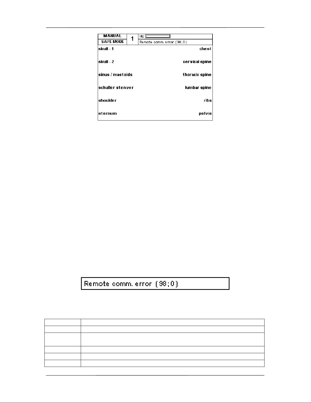
TOP-X100NR USER MANUAL Innomed Medical Inc.
13
The "READY" script changes to "SAFE MODE".
4.3.5 Turn off
Gross errors, the high power parts and the control of the generator must be
deenergised in order to avoid damage. In case of such an error the generator turns
off, the error can not be displayed.
The error can only be read from the log file by a PC-based installation software.
4.4 Log file
All the errors are stored in a log file. The time of the error and its code is stored. The
log file can be read by a PC based installation software.
4.5 Service contact
Please contact the nearest service in case of errors which make the use of the
generator impossible, or are not caused by improper use.
Please inform the service person about the code of the error which is located after
the name of the error in round brackets.
E.g.: Remote comm. error (98;0)
4.6 Basic errors
A list of errors that can appear during normal operation
Error code Description
(1;1), (1;2) The tube is overheated by load. Wait until it cools.
(2;1) Preparation button pressed during tube change. Wait a few seconds
with preparation after device change.
(3;1) Check the tube positioning (Device interlock missing)
(4;1) The examination room door is open.
(18;1) The maximum fluoro time is reached. Reset the time counter.

TOP-X100NR USER MANUAL Innomed Medical Inc.
14
Error code Description
(20;1) The tube is overheated by load. Wait until it cools.
(25;1..512) Error of the power unit during exposure. If regularly happens contact
the service.
(37;0) The set time for tomo exposure was too short.
(47;0) The set mAs value for the AEC-controlled exposure was too little
(51;0) Prep button released during preparation.
(55;0) The generator is overheated by load. Wait until it cools.
(56;0) Exp button released during exposure
(70;0) The ionization chamber has not received sufficient amount of X-Ray.
Check the X-Ray parameters set, and that the sensitive areas of the
ionization chamber receive X-Ray properly.
(71;0) The other exposure button must be used in the current configuration
(76;0) Preparation longer than 10 seconds
(106;0) Attempt to start a tomographic exposure, but the tomo mode was not
selected on the device (there is no tomo-ready signal from the device)
(119;0) Exp button not released 10 seconds after exposure
(122;0) Too little mAs set for an AEC controlled exposure. Check the set X-
Ray parameters.
(137;0) The external device (image processor, PC) is not turned on or is not
ready receiving X-Ray. (Waiting for ready signal on the serial line)

TOP-X100NR USER MANUAL Innomed Medical Inc.
15
5. Anatomical program mode
After turning on, the generator starts with the APR operating mode – a low-power
program.
In the APR operating mode of the TOP-X 100NR 12 buttons (9-20) are reserved in
the APR field (A) for the anatomical programs. Each button is an arbitrary level,
independent anatomical program. During installation it is possible to set each field’s
unique name.
When a body part button (9-20) is pushed, the selected body part’s sub-menu is
displayed. Here 12 body parts or sub-body parts selections are available.
When the anatomical program is displayed (sub body part selection including
settings), all program-related settings appear on the control panel displays.
Selecting an anatomical program (APR) always means the automatic setting of the
next parameters (in this example at the “SKULL AP”).
kV: 70kV
mAs: 40mAs
Device (TECHNIQUE): Vertical Bucky stand
Grid use (GRID): Grid is used
High-speed starter (HS): Not used
Tube (TUBE): Tube 1
Focal spot (FOCUS): Large focal spot
AEC ON/OFF: On
Dominant field (FIELD): 2. (middle) is selected
Film type (SCREEN): M medium film sensitivity
Density correction (DENSITY): "0" (middle setting)
Patient thickness (PATIENT): Normal (average) size
Load (LOAD 100%): Allows max. 80% load
The parameter values retrieved in APR mode are preset to a patient with average
height and weight, but the parameters can be changed anytime.

TOP-X100NR USER MANUAL Innomed Medical Inc.
16
All changes (fatter/thinner patient, film sensitivity selection, etc.) that modify the
default data are supervised by the generator’s software. It is important to note that
these modifications will set only correct values for the anatomical programs until one
of the following buttons will be used:
kV up/down (34,35), mA up/down (36,37), mAs up/down (36,37), sec up/down
(38,39)
Using these buttons will switch the generator into manual mode, in other words an
operating mode with free parameter setting (see section 2.2). In this case all
parameters can be changed freely within the limits of the tube and generator.
Use the APR/SET button (8) to return to the main APR menu.
After exposure the console returns to the last used sub-body part menu. If you would
like to return to the upper body part selection, push the APR/SET button
again.

TOP-X100NR USER MANUAL Innomed Medical Inc.
17
6. Automatic exposure control (AEC)
6.1 The AEC operating mode
When using the AEC operating mode, the so-called ionization chamber placed
between the patient and the film performs the in time exposure stoppage. The
ionization chamber measures the dosage passing through it and stops exposure
when the dosage required for the optimal darkening of the used film is reached.
AEC can be used in both APR and manual mode, but only if AEC mode is configured
for the given examination device. In both cases the AEC function can be turned on or
off according to user preference. In APR mode, depending on body part related
programming the program starts either with or without AEC. The LEDs above the
AEC field buttons (25-27) indicate which fields are used. If any of the three LEDs are
on, the device is operating in AEC mode.
The AEC dominant field buttons (25-27) determine which part of the image is
considered important; while the DENSITY (density correction) buttons (12, 18) let
you set whether to make the image darker or lighter than usual.
In AEC mode the time (sec) or current-time product (mAs) parameters on the RAD
parameter displays (C, D) only indicate the maximum value the generator will allow
during exposure. If this exposure time value or the mAs value is reached during
exposure, the generator will turn off exposure. These are the so-called backup
values. These are protections in case the AEC function is not operational. This can
happen, for example, if X-ray radiation does not reach the ionization chamber,
because the collimator setting is not appropriate.
If the AEC function did not stop the exposure but reaching either the set time or the
set mAs value, the generator displays an error message at the end of the exposure,
warning that the film will most likely be too light. In this case the error message
remains and exposure is disabled until the user pushes any of the buttons on the
console to acknowledge it.
The two backup values have to be set according to the expected mAs value within
the current conditions (FFD, patient size, etc.) and at the given tube voltage (kV).
6.2 AEC operating mode setting possibilities
You can access AEC operating mode by selecting one or more of the AEC dominant
fields (25-27). The LED over the selected field’s button turns on
and the DENSITY field appears on the LCD display (A). The mentioned field is not
accessible in other operating modes. Setting the dominant fields does not affect the
recording parameters.
TOP-X100NR USER MANUAL Innomed Medical Inc.
18
When using AEC, prior to the exposure mAs or sec backup values must be set on
the LED displays (B, C, D) according to the examination. The measured values after
exposure appear floating on the LCD display.
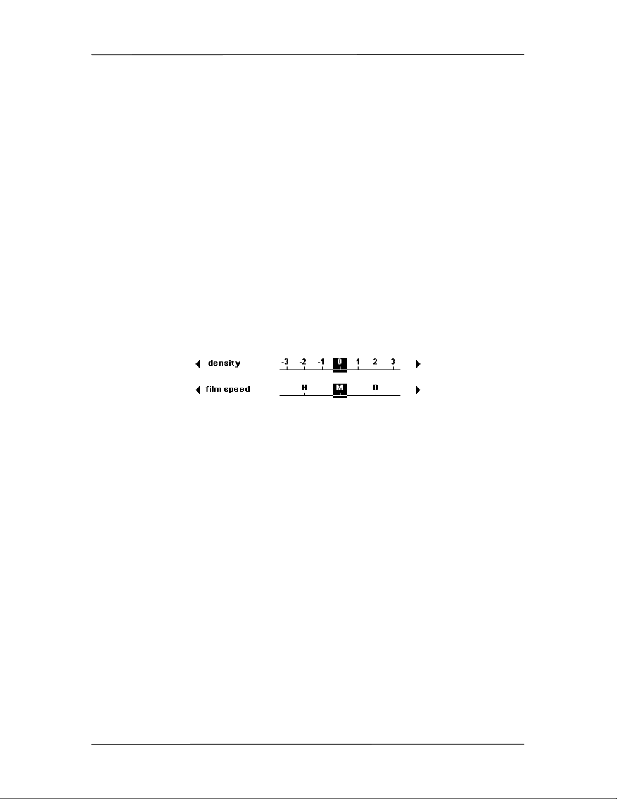
6.2.1 DENSITY – density correction
Density can be set in seven steps in the field (12, 18), which effects the darkening of
the image on the film. The higher the density correction value, the darker the image
will be. The seven values change the dosage value of terminating the exposure
compared to the default value (0) reaching the film:
-3 50%
-2 63%
-1 80%
0 100%
+1 125%
+2 160%
+3 200%
6.2.2 SCREEN – screen selection
Three screen types are available (13, 19). These are usually the following:
• High speed high-sensitivity, but more coarse resolution
• Medium speed medium-sensitivity, medium resolution
• Detailed low-sensitivity, but high resolution, rich in detail
The high-sensitivity screen / film combination requires less dosage, but the resulting
film resolution is lower. The lower sensitivity requires a higher dosage, but the film
quality and resolution is very good.
The user decides what type of screen and film to use considering the examination
characteristics and other conditions. H, M or D type is set accordingly on the console.
The generator automatically corrects the mAs value according to the selection of the
film / screen combination sensitivity. Since there are numerous film and screen types
available in the market, and their sensitivity is variable, the sensitivity values for H, M
and D must be set during generator installation.
This is performed by the installing professional based on the cassettes used at the
workstation. Based on the cassettes, i.e. the used screen / film systems the installing
professional assigns sensitivity values to each of the H, M, D signs (based on the
nominal sensitivity set at 80kV). This way it is easy to reconcile the H/M/D marking
on the control panel with the type indicated on the cassettes.

TOP-X100NR USER MANUAL Innomed Medical Inc.
19
6.3 Verifying the exact operation of the AEC
Make an exposure using AEC. Make sure the film has the same sensitivity as the
film used for calibration during installation. Set 80kV and beam current that result in
radiation period longer than 50ms and shorter than 1s. Place a 15cm water phantom
in the radiation’s path.
After development compare this film to the film made during calibration. The optical
density can only deviate by 0.15 between the two films.
Selecting the correct screen type on the control panel in AEC mode
is extremely important, because when determining the required
dosage, the generator takes into account the selected film / screen
sensitivity as well.

TOP-X100NR USER MANUAL Innomed Medical Inc.
20
7. Parameter setting in manual operating mode
Free parameter setting means that any of the four parameters effecting X-ray quality,
strength and duration can be set freely – within the operating limits of the tube and
the generator, and the device’s allowed accuracy.
The four parameters are the following:
- Ua (the voltage between the X-ray tube anode-cathode, kV)
- Ia (the current flowing through the X-ray tube, mA)
- Te (the time until the tube current exists, ms or s)
- Q (Ia x Te: the product of tube current and time, mAs)
Pushing the APR/SET button (8) or the buttons that directly set the
parameter values (kV, mA, mAs, sec) in anatomical program mode accesses free
parameter setting, also known as manual mode. In manual mode the settings are
only limited by the generator power and the tube specifications.
Use the MODE button (33) to switch between two- and three-point modes.
Three-point mode is the operating mode when the voltage (kV), current (mA) and
time are set. The generator calculates the current – time product (mAs), but does not
display it on the exposure parameter display. To make it visible, push the MODE
button (33) once.
To make the related current (mA) and time values visible in two-point mode (or mAs
mode), push the MODE button
again.
The basic principle of exposure parameter setting is that exposure quality is
generally affected by two factors: X-ray tube voltage (kV) and the current – time
product (mAs). With a given mAs value the X-ray tube current (mA) and exposure
time values are secondary. The only special exceptions to this are a few special
cases, for example tomography or very short exposures. For this reason the
generator, in case of some user selection, can change the current (mA) and time
parameters while leaving the mAs value unchanged.
Following is an example of this feature.
Let us assume that the X-ray tube limit is 48kW at large focal spot and 20kW at
small focal spot at 0.1s exposure time. Enable maximum load (LOAD 100% field).
Set 120kV voltage, 400mA current (this will be 48kW) and 0.1s exposure time.
Switch to two-point mode, 40mAs is displayed. Switch to small focal spot. The small
focal spot cannot handle the 48kW load, so the generator recalculates the current
and time parameters, leaving the X-ray tube voltage (kV) and the mAs values, thus
decreasing the load below the allowed limit. Switch back to three-point mode. The
new indicated values are: 120kV, 125mA (15kW), 0.32s (40mAs). At this example we
Table of contents
Popular Portable Generator manuals by other brands


MULTIQUIP
MULTIQUIP GA-6REA Operation and parts manual

Paradyne
Paradyne Compshere 3000 Series installation guide

Westinghouse
Westinghouse iGen4000DFcv user manual

TESI
TESI XE18PB06 Instructions for use and maintenance

CHICAGO
CHICAGO 66604 Set up, operating, and servicing instructions

MIOX
MIOX RIO ZUNI quick start guide

Briggs & Stratton
Briggs & Stratton PRO4000 Illustrated parts list

Peak Scientific
Peak Scientific Solaris XE user manual

Agilent Technologies
Agilent Technologies N5161A Service guide

Firman
Firman P06702 Operator's manual

Champion Global Power Equipment
Champion Global Power Equipment 200963 quick start guide

Black Max
Black Max BMi2122 Quick reference guide