II 1312 Photoacoustic Multi-gas Monitor
INNOVA
Instruction Manual
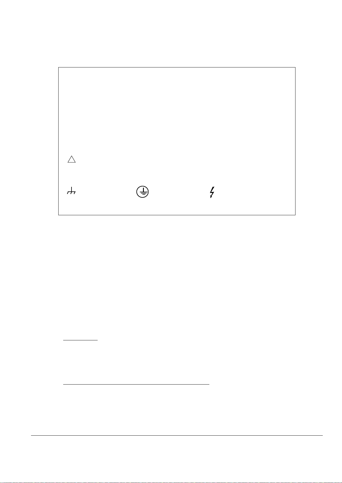
Safety Considerations
The 1312 Photoacoustic Multi-gas Monitor complies with IEC348; Safety
Requirements for Electronic Measuring Apparatus and IEC1010–1; Safety
Requirements for Electrical Equipment for Measurement, Control, and
Laboratory Use, and is supplied in a safe condition. To ensure safe operation
and retain the 1312 in a safe condition, note the following:
EXPLOSION HAZARD!
TO AVOID THE POSSIBILITY OF AN EXPLOSION, MONITORING
OF FLAMMABLE GASES IN EXPLOSIVE CONCENTRATIONS MUST
NEVER BE ATTEMPTED.
Never operate the 1312 Photoacoustic Multi-gas Monitor in potentially explo-
sive environments.
When monitoring potentially flammable or toxic gases it is essential that:
• The instrument itself is placed in a well-ventilated area outside the poten-
tially hazardous zone.
• A sufficiently long tube is connected to the air-outlet on the back panel so
that the sampled gas is carried away to the open air or to an extraction
and/or filtration unit.
WARNINGS!
• Avoid water condensation in the instrument.
• Switch off all equipment before connecting or disconnecting their digital
interface. Failure to do so could damage the equipment.
• Whenever it is likely that the correct function or operating safety of the
apparatus has been impaired, the apparatus must be made inoperative and
be secured against unintended operation.
• Any adjustment, maintenance and repair of the open apparatus under volt-
age must be avoided as far as possible and, if unavoidable, must be carried
out only by trained service personnel.
• If a fault is reported by the monitor that indicates correct function of the
instrument may be impaired, consult your local Innova AirTech representa-
tive. Under no circumstances should repair be attempted by persons not
qualified in the service of electronic instrumentation.