innovair ICS0629C21 User manual

Four-wayInverter CassetteType
INSTALLATION MANUAL
Thankyou verymuchforpurchasing our airconditioner,
Before using yourairconditioner ,pleaseread thismanualcarefullyand keep itfor future reference.
ICS0629C21
ICS0736C21
ICS0848C21

1
installationmanual
1.PRECAUTIONS
The saftyprecautionslistedhere are divided intotwo categories.
After completing the installation,makesure thatthe unitoperates
properlyduring the start-upoperation.Pleaseinstructthe customer
onhowtooperatetheunitand keepitmaintained.Also,inform
customersthattheyshouldstore thisinstallation manualalong with
the owner's manualfor future reference.
Be sureonlytrainedand qualifiedservice personnelto
install,repairor servicetheequipment.
Improperinstallation,repair,and maintenancemayresultin
electricshocks,short-circuit,leaks,fire orotherdamageto
the equipment.
Ifyou do notfollow theseinstrutionsexactly,the unitmay
causepropertydamage,personalinjuryor loss oflife.
Ifyou do notfollow theseinstrutionsexactly,theunitmay
causeminorormoderatepropertydamage,personal
injury.
CONTENTS PAGE
Installaccording tothisinstallation instructionsstrictly.
Ifinstallation isdefective,itwill causewaterleakage,
electricalshockand fire.
Wheninstalling theunitinasmallroom, takemeasures
against tokeeprefrigerantconcentration fromexceeding
allowablesafety limits intheeventofrefrigerantleakage.
Contact theplaceofpurchaseformoreinformation.
Excessiverefrigerantinaclosed ambientcanlead tooxygen
deficiency.
Use theattachedaccessories parts and specifiedparts
for installation.
otherwise,itwillcausethe settofall,waterleakage,
electricalshockand fire.
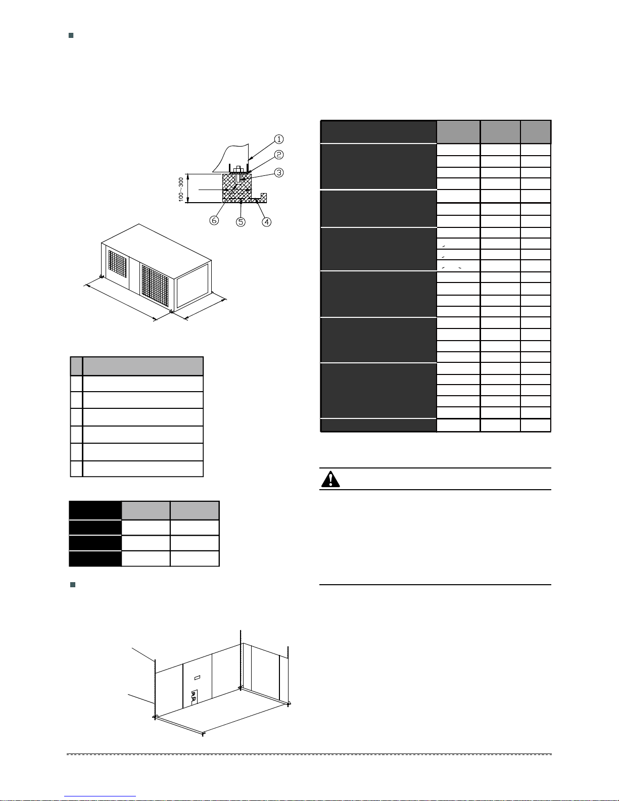
Installatastrong and firmlocation whichisableto
withstandtheset'sweight.
Ifthe strengthisnotenough or installation isnotproperly
done,the setwill droptocauseinjury.
Theappliancemust beinstalled2.5mabove floor.
Theapplianceshall notbeinstalledinthelaundry.
Beforeobtaining accesstoterminals,allsupplycircuits
must bedisconnected.
Theappliancemust bepositionedsothat theplugis
accessible.
Theenclosureoftheappliance shallbemarkedbyword,
or bysymbols,withthedirection ofthefluidflow.
For electricalwork,followthelocalnationalwiring
standard,regulation and thisinstallation instructions.An
independentcircuitand singleoutlet must beused.
Ifelectricalcircuitcapacityisnotenoughordefect in
electricalwork,itwill causeelectricalshock or fire.
Use thespecifiedcableand connecttightlyandclamp
thecablesothatno externalforce willbeactedon the
terminal.
Ifconnection or fixing isnotperfect,itwill causeheat-up or
fireatthe connection.
Wiring routingmust beproperlyarrangedsothatcontrol
boardcoverisfixedproperly.
If controlboardcoverisnotfixedperfectly,itwill cause
heat-upatconnectionpointofterminal,fireorelectrical
shock.
Ifthesupplycord isdamaged,itmustbereplacedbythe
manufactureor its service agentor asimilarlyqualified
personinordertoavoidahazard.
Anall-poledisconnectionswitchhaving acontact
separationofatleast3mminallpolesshouldbe
connectedinfixedwiring.
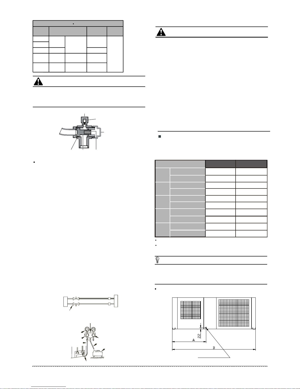
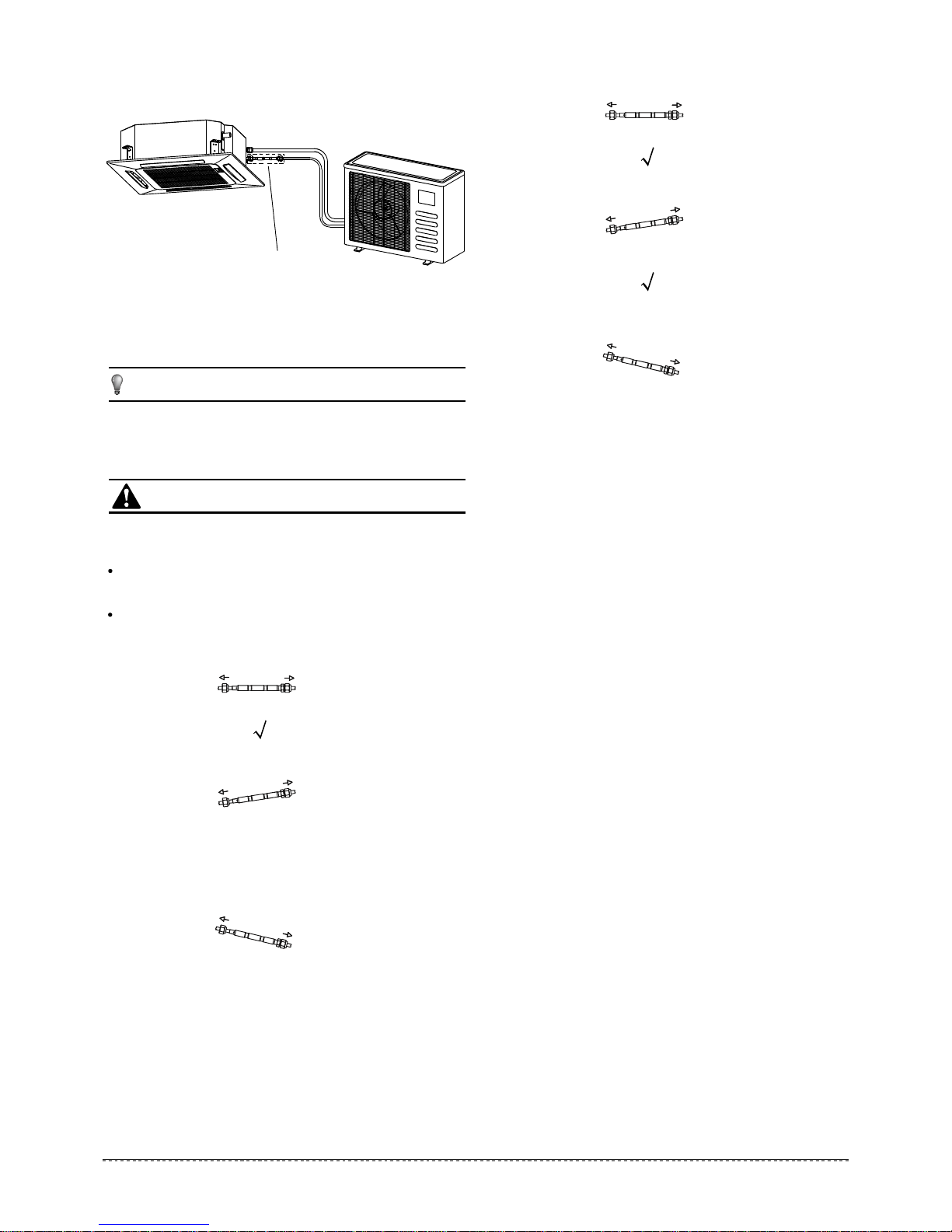
Whencarryingoutpiping connection,take carenottolet
airsubstances go intorefrigeration cycle.
Otherwise,itwillcauselowercapacity,abnormalhigh
pressure inthe refrigeration cycle,explosion and injury.
Donotmodify thelengthofthepowersupplycordor use
ofextensioncord,and donotsharethesingleoutlet with
otherelectricalappliances.
Otherwise,itwill causefire or electricalshock.
Carryoutthespecifiedinstallationworkaftertaking into
accountstrong winds,typhoonsor earthquakes.
Improperinstallationworkmayresultinthe equipmentfalling
and causingaccidents.
CAUTION
WARNING
WARNING
PRECAUTIONS......................................................................
INSTALLATIONINFORMATION.............................................
ATTACHEDFITTINGS............................................................
INSPECTINGAND HANDLINGTHEUNIT.............................
INDOORUNITINSTALLATION..............................................
OUTDOORUNITINSTALLATION..........................................
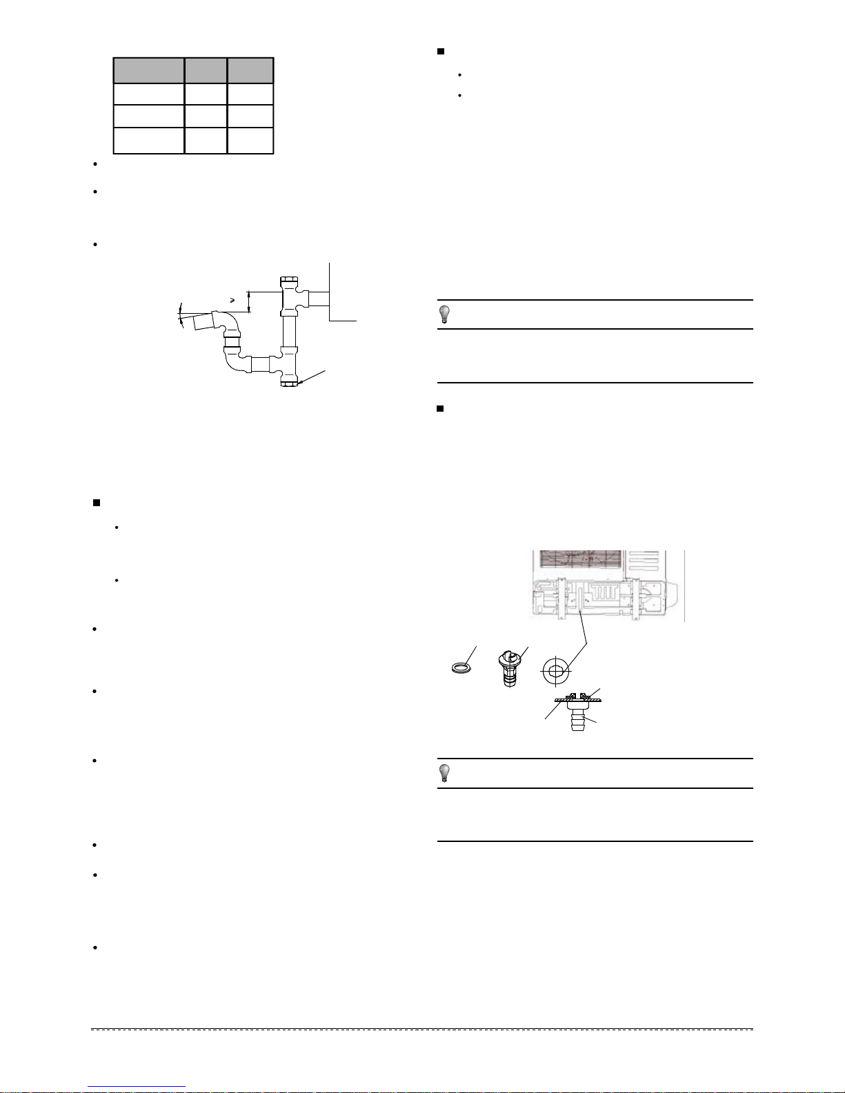
INSTALLTHECONNECTINGPIPE.......................................
CONNECTTHEDRAINPIPE................................................
CONNECTIVEDIAGRAM.....................................................
WIRING...................................................................................
TESTOPERATION.................................................................
1
2
3
4
4
11
15
18
19
20
21
CONTENTS PAGE
Keepthismanual wheretheoperator caneasilyfind them.
Readthismanual attentivelybeforestarting uptheunits.
For safety reasontheoperator mustreadthefollowing
cautionscarefully.
IfusedasMULTIunit,pleaserefertotheInstallation &
operation manualspackedwithoutdoor unit.

2
installationmanual
Toinstallproperly,please readthis"installationmanual"at
first.
Theairconditionermust beinstalledbyqualifiedpersons.
Wheninstallingtheindoor unitor its tubing,please follow
thismanualas strictlyas possible.
Iftheairconditionerisinstalledonametalpartofthe
building,itmustbeelectricallyinsulatedaccording tothe
relevantstandardstoelectricalappliances.
Whenalltheinstallationworkisfinished,please turnon
thepoweronlyafterathoroughcheck.
Regret for nofurtherannouncementifthereisanychange
ofthismanualcausedbyproduct improvement.
2.INSTALLATIONINFORMATION
Groundtheairconditioner.
Donotconnect thegroundwiretogasorwaterpipes,
lightning rodor atelephonegroundwire.Inappropriate
groundingmayresultinelectricshocks.
Be suretoinstallanearthleakagebreaker.
Failuretoinstallanearthleakagebreakermayresultin
electricshocks.
Connecttheoutdoorunitwires ,thenconnect theindoor
unitwires.
You are notallowed toconnectthe airconditioner withthe
powersupplyuntil the wiring and piping isdone.
Whilefollowingtheinstructionsinthisinstallation
manual,install drainpipinginordertoensureproper
drainageandinsulatepipinginordertoprevent
condensation.
Improperdrainpipingmayresultinwaterleakageand
property damage.
Installtheindoorand outdoorunits,powersupplywiring
andconnectingwires shouldbeat least 1meteraway
fromtelevisionsor radiosinordertopreventimage
interference or noise.
Depending on the radiowaves,adistanceof1meter maynot
be sufficientenough toeliminatethe noise.
Theappliance isnotintendedfor use byyoung children
or infirmpersonswithoutsupervision.
Don'tinstalltheairconditionerinthefollowing
circumstance:
There ispetrolatumexisting.
There issalty airsurrounding(near the coast).
There iscausticgas (the sulfide, for example) existing
inthe air(near ahotspring).
The Voltvibratesviolently (inthe factories).
Inbusesor cabinets.
Inkitchen where itis full ofoil gas.
There isstrongelectromagneticwaveexisting.
There are inflammablematerials orgas.
There isacidor alkaline liquidevaporating.
Otherspecialconditions.
Iftherefrigerantleaks duringinstallation,ventilatethe
area immediately.
Toxicgasmaybe produced ifthe refrigerantcomesintothe
placecontacting withfire.
Thetemperatureofrefrigerantcircuitwillbehigh,please
keeptheinterconnectioncableaway fromthecopper
tube.
Aftercompleting theinstallation work,checkthat the
refrigerantdoesnotleak.
Toxicgasmaybe produced ifthe refrigerantleaksintothe
roomand comesintocontactwithasourceoffire,suchasa
fan heater,stoveorcooker.
INSTALLATIONORDER
Selectthe location;
Installthe indoor unit;
Installthe outdoor unit;
Installthe connecting pipe ;
Connectthedrainpipe;
Wiring;
Testoperation.
CAUTION
Theapplianceshall beinstalledinaccordancewith
nationalwiringregulations.
Donotoperate your airconditionerinawet roomsuch
as abathroomor laundryroom.
Anall-poledisconnectiondevicewhichhasat least 3mm
clearances inallpoles ,and havealeakagecurrentthat
mayexceed10mA,theresidualcurrentdevice(RCD)
having aratedresidualoperating currentnotexceeding
30mA,anddisconnectionmust beincorporatedinthe
fixedwiringinaccordance withthewiringrules.

3
installationmanual
3.ATTACHEDFITTINGS
Pleasecheckwhether the following fittingsare offullscope.Ifthere are somespare fittings,pleaserestore themcarefully.
QUANTITY
Tubing&Fittings
Remote controller&Its Frame
DrainpipeFittings
Installation Fittings
SHAPENAME
13.Expansiblehook
3.Out-letpipe sheath
4.Out-letpipe clasp
5.Drainjoint(onsomemodels)
6.Sealring(onsomemodels)
11.Owner'smanual
12.Installation manual
7.Remotecontroller
8.Remotecontroller holder
9.Mountingscrew(ST2.9
10-C-H)
10.Alkaline drybatteries(AM4)
14.Installation hook
1.Installation paper board
(on somemodels)
(on somemodels)
(on somemodels)
(on somemodels)
4
1
4
1
1
1
1
1
1
1
2
2
1
1
2.Soundproof/insulation sheath
15 .Orifice
16 .Transfer connector( 12.7- 15.9)
(Packed withthe indoor unit )
(NOTE:Pipesizediffer fromappliance
toappliance.Tomeetdifferentpipe size
requirement,sometimesthe pipe
connectionsneedthe transfer connector
toinstallon the outdoor unit .)
18 .Transfer connector( 9.52- 12.7)
(Packed withthe indoor unit used for
multi-type modelsonly)
(NOTE:Pipesizediffer fromappliance
toappliance.Tomeetdifferentpipe size
requirement,sometimesthe pipe
connectionsneedthe transfer connector
toinstallon the outdoor unit .)
1
1
(on somemodels)
1
(on somemodels)
17 .Transfer connector( 6.35- 9.52)
(Packed withthe indoor unit )
(NOTE:Pipesizediffer fromappliance
toappliance.Tomeetdifferentpipe size
requirement,sometimesthe pipe
connectionsneedthe transfer connector
toinstallon the outdoor unit .)
1
(on somemodels)
Installation accessory
(Theproduct youhave mightnotbe
providedthefollowing accessory)
(Theproduct youhave mightnotbe
providedthefollowing accessory)

4
installationmanual
Keep indoor unit,outdoor unit,power supplywiring and
transmission wiring atleast1meter awayfromtelevisions
and radios.Thisistopreventimageinterferenceand
noiseinthoseelectricalappliances. (Noisemaybe
generated depending on the conditionsunder whichthe
electric waveis generated,even if1meter iskept.)
There isenough roomforinstallation and maintenance.
The ceiling ishorizontal,and itsstructure canendurethe
weightofthe indoor unit.
Theoutletandtheinletarenotimpeded,andthe
influenceof externalairis the least.
The airflowcanreachthroughoutthe room.
The connecting pipe anddrainpipe couldbe extracted out
easily.
There isno directradiation fromheaters.
4.INSPECTINGANDHANDLINGTHEUNIT
Atdelivery,thepackage shouldbecheckedand anydamage should
be reported immediatelytothe serviceagent.
When handling the unit,takeintoaccountthe following:
5.INDOORUNIT INSTALLATION
5.1Installation place
(Refer toFig.5-1,Fig.5-2,Fig.5-3 and Table5-1 for specification.)
Theindoor unitshouldbeinstalledinalocationthat meets
thefollowingrequirements:
5.2Installation procedures forfreshair
intake ductconnection
5.3.1Installthemainbody(cassettetype
airconditioner)
Cutaquadrangularholeof880x880mm intheceiling
according tothe shapeofthe installation paper board.
(Refer toFig.5-2)
The center ofthe holeshouldbe atthe samepositionof
thatoftheairconditioner body.
Determinethe lengthsand outletsofthe connecting pipe,
drainpipe and cables.
Tobalancetheceilingandtoavoidvibration,please
enforcetheceiling when necessary.
Adjustthe hexangular nutson thefour installation hooks
evenly,toensurethe balanceofthe body.
Ifthedrainpipeisawry,leakage willbe caused bythe
malfunction ofthe water-levelswitch.
Adjustthe position toensurethegapsbetween the body
and the foursidesofceiling are even.The body'slower
partshouldsinkintotheceilingfor18 mm (Referto
Fig.5-6).
Ingeneral,Lishalfofthe screw lengthofthe installation
hook.(Refer toFig.5-6)
Locatethe airconditioner firmlybywrenching the nuts
after havingadjusted the body'sposition well.(Refer to
Fig.5-7)
Selectthe position ofinstallation hooks according tothe
hookholeson the installation board.
Drill four holesof Ø12mm, 45~50mmdeep at the selected
positionsontheceiling.Thenembedtheexpansible
hooks (fittings).
Facethe concaveside ofthe installation hooks toward the
expansiblehooks.Determine the lengthofthe installation
hooksfromtheheightofceiling,thencutoffthe
unnecessarypart.
If theceilingisextremelyhigh,pleasedeterminethe
lengthofthe installation hookaccording tofacts.
1
2
3
1
2
3
4
Newbuilthouses andceilings
Inthe caseofnew builthouse,the hookcan be embedded
inadvance(refer to2mentioned above).Butitshouldbe
strong enough tobear the indoor unitand will notbecome
loosebecauseofconcreteshrinking.
After installing the body,pleasefasten theinstallation paper
boardontotheairconditionerwithbolts(M6X12)to
determine inadvancethe sizesand positionsofthe hole
opening on ceiling.(Refer toFig.5-8)
Refer to3abovefor installation.
Removethe installation paper board.
Pleasefirst guaranteetheflatnessandhorizontalof
ceiling when installing it.
Refer to1mentionedabovefor others.
Afterinstalling thebody,thefour bolts(M6x12)must be
fastenedtotheairconditionerontoensurethebodyis
groundedwell.
Fragile,handlethe unitwithcare.
Keep the unituprightinordertoavoidcompressor
damage.
Chooseon before hand thepathalong whichthe unitistobe
broughtin.
Movethisunitasoriginally package aspossible.
When liftingthe unit,alwaysuseprotectorstopreventbelt
damage and payattention totheposition ofthe unit’scentre
ofgravity.
1
2
3
4
CAUTION
CAUTION
Preparingtheconnection hole
Theexistingceiling (tobehorizontal)
Placingtheinsulation
Cutoff the knockoutholeon the side platewithanipper.
Cutthe innerinsulation ofthe holeportion withacutter.
(Refer toFig.5-4)
Puttheinsulationtightlyaroundthe holeoftheunitas
shown.
The endsofthe side plateand the inner insulation mustbe
completelyadhered withoutleaving anyclearancealongthe
circumferenceofthe hole.
Makesure the innersurfaceofinsulation tightlycontactsthe
inner insulation edge and the side plate. (Refer toFig.5-5)

5
installationmanual
Drainside
Tubingside
(Unit: mm)
780(Hook-location)
840(Body)
950(Panel)
>1000mm
>1000mm
Ceiling
880mm(ceiling hole)
Ground
Panel
Inlet
Outlet Outlet
Fig.5-2
Fig.5-4
Fig.5-1
Fig.5-3
Fig.5-5
Fig.5-7Fig.5-6
Innerinsulation
Innerinsulation
±10mm
Body
Ceiling
Drainpiper
piping
Slit
Sideplate
Connectingpointof
refrigerant pipe
Connectingpointof
refrigerant pipe
(Gasside ØB)
(Liquidside ØC)
Connectingpointof drainpipe
Innerinsulation
Sideplate
Sideplate
Insulation(local)
Insulation(local)
Bolt M6X12
Fig.5-8
Central hole
Installation
paperboard
Body
Table5-1 mm
MODEL A H
18
30~60
>260
>330
230
300
Remark
R410A&R22 Cooling/Cooling & Heating
24 >260230
R410A&R22 Cooling/Cooling & Heating
>330300
R410A&R22 Cooling/Cooling & Heating

6
installationmanual
Fig.5-11
Fig.5-10
Gridswitch
Fig.5-9
<200mm Leanover1/50
Pump-pipeclasp
(thefittings)
panel sponge
body
Ceiling
panel
panel foam1airout
Fan panel foam2
Loosenuppernut
Adjust lowernut
Gapnotallowed
outletfoam
1-1.5m
Pumpjoint
Test mouth
Body
Water-receiver
Test cover
Stowtube
Drainplug
Fig.5-12
Fig.5-14
Fig.5-16
Fig.5-17
Fig.5-13
Fig.5-15
Fig.5-18
Tubingjoint
Outletjoint
Hook panel
Water-receiver
SwingMotor
Hook-bolt
Cross-screwdriver
Leakage
Installationcover’s rope
TapScrew Slidethefour sliders
inthecorresponding
channel wheninstalling
thecover
Ceiling
Pollution Water condensation

7
installationmanual
Fresh air intake (ф65)
5.3.2Installthemainbody(smallcassette
typeairconditioner)
5.4.1InstallThePanel(cassettetypeair
conditioner)
Remove theair-ingrill.
Neverputthepanelface down on flooror againstthe
wall,or on bulgyobjects.
Nevercrashor strike it.
Slide two grill switchestoward the middleatthe sametime,
and thenpull themup. (Refer toFig.5-9)
Drawthe grillup toan angleofabout45,and removeit.
(Refer toFig.5-10)
Remove theinstallationcoversatthefourcorners
Wrenchoffthe bolts,loosethe rope ofthe installation covers,
and removethem. (Refer toFig.5-11)
1
2
CAUTION
Central hole
Hook hole
Installation paper board
Body
Fixinghole
installationpaper board
Drainside
(Unit:mm)
545(Hook-location)
570(Body)
647(Panel)
Fig.5-20
Fig.5-19
Fig.5-21
Fig.5-22
Fig.5-23
Fig.5-24
Fig.5-25
All the picturesinthis manualare for explanation purposeonly.
Theymaybe slightlydifferentfromthe airconditioner you
purchased(depend on model).The actualshape shall prevail.
NOTE
Necessaryroom
Ground
OutletOutlet Inlet
A
>1000
>1000
Colourless
transparentpipe
Ceiling Panel
Hook
A
Nut
Body
600
Horizontal
indicator
Screw M5x16
(Accessory)
50

8
installationmanual
5.4.2InstallThePanel(samllcassettetype
airconditioner)
Donotcoilthewiringoftheswingmotor intotheseal
sponge.
Installthepanel
Align theswing motor onthe paneltothe tubing jointsofthe
bodyproperly. (RefertoFig.5-12)
Fixhooks ofthe panelatswing motor and itsoppositesides
tothehooksofcorrespondingwaterreceiver. (Referto
Fig.5-12.1) Thenhangtheothertwopanelhooksonto
corresponding hangers ofthe body. (RefertoFig.5-12.2)
Adjust thefourpanelhookscrewstokeepthepanel
horizontal, and screw themup tothe ceiling evenly. (Referto
Fig.5-12.3)
Regulatethe panelinthedirection ofthe arrow in Fig.5-12.4
slightlytofitthepanel'scenter tothe centerofthe ceiling's
opening.Guarantee thathooks offour corners arefixed well.
Keep fastening thescrewsunder the panelhooks,until the
thicknessofthesponge between the bodyand the panel's
outlethasbeenreduced toabout4~6mm.The edge ofthe
panelshouldcontactwiththe ceiling well. (RefertoFig.5-13)
3
4
5
6
Fastentheropeofinstallationcoverontheboltofthe
installation cover. (Refer toFig.5-16-left)
Press the installation cover intothe panelslightly. (Refer to
Fig.5-16-right)
Malfunctiondescribedin Fig.5-14 canbecausedby
inappropriatetightnessthe screw.
Ifthe gap betweenthe paneland ceiling still existsafter
fasteningthe screws,the heightofthe indoor unitshould
be modified again. (RefertoFig.5-15-left)
You can modifythe heightofthe indoor unitthrough the
openingson thepanel'sfourcorners, iftheliftofthe
indoor unitandthe drainpipe isnotinfluenced (Refer to
Fig.5-16-right).
Hang theair-ingrilltothepanel,thenconnect thelead
terminator oftheswingmotor andthat ofthecontrolbox
withcorresponding terminatorson thebodyrespectively.
Relocate theair-ingrillintheprocedureofreversedorder.
Relocate theinstallation cover.
CAUTION Fig.5-27
Fig.5-28
Remove theair-ingrill.
Neverputthepanelfacedown onfloor oragainst the
wall,or on bulgyobjects.
Nevercrashor strike it.
Slidetwogrillswitchestoward the middleatthe sametime,
and thenpull themup.(Refer toFig.5-27)
Drawthe grill up toan angleofabout45,andremoveit.
(Refer toFig.5-28)
1
CAUTION
Gridswitch
Theinstallation coveroftheswing motor must sinkinto
thecorrespondingwaterreceiver.
Installthepanel
Alignthe swing motor on thepaneltothe tubingjoints ofthe
bodyproperly.(RefertoFig.5-29)
Hangthefourfixed ropeofthe mainbodytothe installation
cover and the other three coversoftheswingmotor:(Refer
toFig.5-29 and )
Installthepanelon the mainbodywithbolt (M5 16) and
washer.(Refer toFig.5-29 )
Adjustthefourpanelhookscrewstokeepthepanel
horizontal,and screw themup tothe ceiling evenly.
Regulatethepanelinthedirection ofthe arrowinFig.5-29.
slightlytofitthe panel'scenter tothecenter ofthe ceiling's
opening.Guarantee thathooks offour corners arefixed well.
Keep fasteningthe screwsunderthepanelhooks,untilthe
thicknessofthe sponge between the bodyand thepanel's
outlethasbeen reduced toabout4~6mm.The edge ofthe
panelshouldcontactwiththe ceiling well. (RefertoFig.5-30)
2
4
5
MalfunctiondescribedinFig.5-31 canbecausedby
inappropriatetightnessthe screw.
If the gap between thepanelandceiling stillexists after
fasteningthe screws,the heightoftheindoorunitshould
be modified again.(RefertoFig.5-32-left)
You canmodify the heightofthe indoorunitthrough the
openingsonthepanel'sfourcorners,ifthe liftofthe
indoorunitand the drainpipeisnotinfluenced (Referto
Fig.5-32-right).
Hang theair-ingrill tothepanel, thenconnectthelead
terminator oftheswing motor and that ofthecontrolbox
withcorresponding terminatorson thebodyrespectively.
Relocate theair-ingridintheprocedureofreversedorder,
installtheair-ingrid.
CAUTION

9
installationmanual
Fig.5-33
Distributionduct
Distributionduct
Distributionduct
Distributionduct
Freshair
Freshairintake(75)
5.5.1Installthedistribution duct(cassettetypeairconditioner)
Conditionedaircanbedistributes bymeansofadistributionduct.
Fig.5-29
Fig.5-30
Body
Panelfoam2Ceiling
Panelfoam
Airplate Panel Panelfoam1
Panelsealingfoam
Inlet air
Outlet air
Cover
Steelrope
Swingmotorinstallation cover
1 2
3
Cover
Steelrope
Swing motor installationcover
1 2
3
Swing motorside
Drainside
Bolt, washer
4
3
Pleaseoperateaccording
tothe directionofthearrow,
orit can notbedisassembled
whenit isnecessary.
Fig.5-31
Fig.5-32
Ceiling Leakage
Dew
Hexagonnut
Ceiling
Horizontaladjust ment
80mm
Ø75mm
MODLE (18-60)

10
installationmanual
Distributionduct
Distributionduct
Fig.5-34
Fig.5-35
Fig.5-36
One-way
Two-way
Two-way
5.5.1Installthedistribution duct(small
cassettetypeairconditioner)
Conditionedaircanbedistributes bymeansofadistribution
duct.
model18 to24 SeriesA=350mm;Series B=85mm
model36 to60 SeriesA=350mm;Series B=155mm
The airvolumeinductisaround 300-360m3/hformodel18
to24 unit.
The airvolumeinductisaround 400-640m3/hformodel36
to60 unit.
The max.lengthofductis2m.
The originalairoutletwiththesamedirection ofductshould
be sealed Incaseoftwo ductconnection.
The airvolumeinone ductisaround 200-260m3/hfor model
18 to24 unit.
The airvolumeinone ductisaround 300-500m3/hfor model
36 to60 unit.
The max.lengthofductis1.5mfor one duct.
The originalairoutletwiththesamedirection ofductshould
be sealed.
Incase ofoneduct connection
Incase oftwo duct connection
The airvolumeinductisaround 180-300m3/hformodel12
to18 unit.
The max.lengthofductis1m.
The originalairoutletwiththesamedirection ofductshould
be sealed Incaseoftwo ductconnection.
The airvolumeinone ductisaround 100-200m3/hfor model
12 to18 unit.
The max.lengthofductis0.75mfor one duct.
The originalairoutletwiththesamedirection ofductshould
be sealed.
Incase ofoneduct connection
Incase oftwo duct connection
NOTE
model12 to18 SeriesA=150mm
NOTE
Freshair
One-way
Freshairintake(75)
Ø65mm Ø75mm
MODLE(12-18)

11
installationmanual
6.1Installation Place
6.OUTDOORUNIT INSTALLATION
There isenough roomforinstallation and maintenance.
The airoutletand the airinletare notimpeded,and can
notbe reached bystrongwind.
Itmustbe adryand well ventilating place.
Thesupportisflatandhorizontalandcanstandthe
weightofthe outdoorunit.Andwill no additionalnoiseor
vibration.
Yourneighborhood willnotfeeluncomfortablewiththe
noiseor expelled air.
Itiseasytoinstallthe connecting pipesor cables.
Determinethe airoutletdirection where thedischarged
airisnotblocked.
There isno danger offire due toleakageofinflammable
gas.
The pipinglengthbetween the outdoor unit and the indoor
unitmay notexceedthe allowablepiping length.
Inthecasethatthe installation placeisexposed tostrong
wind suchasaseaside,makesure the fan operating
properlybyputting the unitlengthwisealongthewall or
using adustshield.(Refer toFig.6-1)
Ifpossible,do notinstall the unitwhere itisexposed to
direct sunlight.
Ifnecessary,install ablindthatdoesnotinterfere withthe
airflow.
Fig.6-1
Theoutdoorunitshouldbeinstalledinthelocation that
meetsthefollowingrequiements:
Allthefiguresinthismanualareforexplanation
purposeonly.Theymaybe slightlydifferentfromthe air
conditioner you purchased.The actualunitshallprevail.
NOTE
Duringtheheatingmode,the waterdrainedoffthe
outdoor unit,Thecondensateshouldbewelldrained
awaybythe drainholetoanappropriateplace,soasnot
tointerfereother people.
Selecttheposition where itwill notbe subjecttosnow
drifts,accumulation ofleavesor other seasonaldebris.If
unavoidable,pleasecoveritwithashelter.
Locatetheoutdoor unitasclosetothe indoor unitas
possible.
Ifpossible,pleaseremovetheobstaclesnearbyto
preventtheperformancefrombeing impeded bytoo little
ofaircirculation.
Theminimumdistancebetweentheoutdoorunitand
obstaclesdescribedintheinstallationchartdoesnot
mean thatthe sameisapplicabletothe situationofan
airtightroom.Leaveopentwoofthe three
directions.(Refore toFig.6-4,Fig.6-5)

12
installationmanual
845 560 335 360 312 700320
760 530 290 315 270 590285
760 530 290 315 270 590285
Fig.6-2
Fig.6-4
Fig.6-3
Fig.6-6
Table6-1 mm
A
A
A
B
C
Fig.6-5
1.Splittype outdoor unit
2.Verticaldischarge type outdoorunit
6.2Figureofbodysize
MODEL A B C D E HF
24
18
30
36
845
938
560
634
634
335
404
404
360
448
448
312
368
368
700
1369
1369
320
900 590 333 355 302 860315
990 624 366 396 340 965345
990 624 366 396 340 965345
990 624 366 396 340 965345
990 624 366 396 340 965345
392
938 634 404 448 368 1369392
990 624 366 396 340 965345
392938
590 378 400 330 1170350900
42
48
60
12 Fig.6-2
780 548 266 300 241 540250 Fig.6-2
Fig.6-2
Fig.6-2
Fig.6-2
Fig.6-2
900 590 333 355 302 860315 Fig.6-2
Fig.6-2
Fig.6-2
Fig.6-2
Fig.6-3
Fig.6-2
Fig.6-3
Fig.6-2
Fig.6-3
Fig.6-3
590 378 400 330 1170350900
Fig.6-3
634 404 448 368 1369392938
Fig.6-3

13
installationmanual
Table6-3
>300mm
>300mm
Airinlet
Airinlet
Fig.6-10
Fig.6-11
(Wall or obstacle)
(Wall or obstacle)
Fig.6-9
>300mm
>600mm
(Wall or obstacle)
Maintainchannel
Airoutlet
Airinlet
M
P
Airinlet
N
Fig.6-8
Fig.6-7
A
B
D E
F
H
I J
G
C
mm
a) Incasethatsuspending inthe ceiling
3.Centrifugalfan outdoor unit
1.Splittype outdoor unit
2.Verticaldischarge type outdoorunit
6.3Space ofinstallation and maintenance
Table6-2 mm
BA C
633 554 554
633 554 554
759
759
710 710
710 710
843 710 710
MODEL
DIMENSIONS
48
60
36
24
18
Refore to
Fig.6-5
Fig.6-6
REMARK
A
1381
1394
1174
B
1328
1338
1120
C
702
783
680
D
740
820
720
E
770
850
750
F
520
568
475
G
336
398
300
H
500
574
430
I
296
342
265
J
443
463
13941338783820850568398574342463
1338783820850568398574342463
393
MODEL
30-36
30-36
48
60
18
11741120680720750475300430265393
24
1394

14
installationmanual
6.5Moving and installation
Fig.6-15
Allthefiguresinthismanualareforexplanation
purposeonly.Theymaybe slightlydifferentfromthe air
conditioner you purchased.The actualunit shall prevail.
Sincethegravity center ofthe unitisnotatitsphysical
center,sopleasebe carefulwhen lifting itwithasling.
Never holdthe inletofthe outdoorunittopreventitfrom
deforming.
Do nottouchthe fan withhandsor other objects.
Do notlean itmore than45,and do notlayitsidelong.
Makeconcretefoundation accoding tothesepecificationsof
the outdoor units.
Fasten the feetofthisunitwithbolts firmlytopreventitfrom
collapsing incaseofearthquakeor strong wind.(Refer to
Fig.6-15)
NOTE
Fixwithbolt
6.4Availableconfiguration forcentrifugalfan
typeoutdoorunit
NOTE
Four differentconfiguration areavailableforoudoorunitonly
changingthe panelsandfan position.
Keep inmind thatfan unitweightis aprox30kg,the unitas
well asrelevantequipmentcovered withthe vinylcover
during installation work.
Tochange airinletisonlynecessarytointerchangethe
indicated panels position.Bothpanelsuse screws tobe fixed
tounitchassis.
Tochange airoutletisnecessarytointerchangepanelstoo.
Fan outletpanelisattached tofan structure,whichmustbe
mounted asfollow.
Airinlet modification
ChangePanel
Fig6-13
Fig.6-14
Allthefiguresinthismanualareforexplanation
purposeonly.Theymaybe slightlydifferentfromtheair
Theactualunitshallprevail.
NOTE
Fig.6-12
b)Incasethatinstalling onthe floor
conditioner you purchased.

15
installationmanual
Foundationcouldbe on flatand isrecommended be 100-300mm
higher thanground level.
Installadrainage around foundation for smoothdrain
When installing the outdoor unitfixthe unitbyanchorbolts of
M10.
When installing the uniton arooforaveranda,drainwater
sometimesturnstoiceonthe coldweather.Therefore,avoid
draining inan area thatpeopleoften usebecauseitisslippery.
1
2
3
4
1
TheProcedureofConnecting Pipes
7.1
Allfieldpipingmustbeprovidedbyalicensed
refrigeration technicianandmustcomplywiththe
relevantlocalandnationalcodes.
Preventlet air,dust,or otherimpurities enterthepipe
system during installation.
Insulation pipeshallbeusedtothegas piping and the
liquidpiping.Otherwise,thecondensatemayhappen
CAUTION
7.INSTALLTHECONNECTINGPIPE
Check whethertheheightdropbetweentheindoor unitand
outdoor unit,thelengthofrefrigerantpipe,and thenumberof
thebendsmeet thefollowing requirements:
(The numberofthe bendsless than 15.) unit: m
ConcreteFoundation
1.Suspend theunitasthedrawingindicates.
2.Ensure thatceilingcanresist theOutdoor unit weightindicated
inspecification labelplate.
Suspendedunit
No Description
1OutdoorUnit
2 Vibration-proofrubber
3Anchor BoltM10
4Drainage (Wide 100 Depth150)
5Drainage
6Mortar Hole(Φ100 Depth150)
Sling Bolt
Suspension Bracket
Table6-4
Table6-5 mm
MODEL
Unit BC
1120 720
1328 740
1338 820
18~24
30~36
30~48
Fig.6-16
Fig.6-17
≥100
Table7-1
R410A
Drill aholeinthe wall(suitablejustfor the sizeofthe wall
conduit),thenseton thefittingssuchasthewall conduitand
itscover.
Model
12K
18K-24K
30K-42K
12K
18K-24K
30K-60K
48K-60K
<15K
>15K~<24K
>24K~<36K
>36K~<60K
50Hz T1condition/R22
Splittypeairconditioner
50Hz Verticaldischargeairconditioner
/60Hz T1condition/R22Splittypeair
conditionerandVertical dischargeair
conditioner
Thetypeofmodels
R410AinverterSplittypeair
conditionerandCentrifugal
fanoutdoorunit
50
30
15
50
30
15
30
65
30
25
50
R410ASplittypeairconditioner
andCentrifugal fanoutdoorunit
50Hz/60Hz T3condition
(outdoorunitdown)
50Hz/60Hz T3condition
(outdoorunitup)
theunitwithquick joint
12K
48K-60K
18K-30K
36K
18K-24K
42K-60K
30K
36K
18K-24K
12K-18K
48K-60K
42K
30K
36K
50
25
15
30
50
30
25
30
25
50
30
30
50
15
35
5 5
25
20
30
25
15
8
20
25
15
10
20
30
20
10
25
25
10
8
20
10
8
20
refrigerantpipe
The lengthofheightdrop
The max

16
installationmanual
2
3
5
6
7
Bind the connecting pipe andthe cablestogether tightlywith
binding tapes.
Pass the bound connecting pipe through the wall conduct
fromoutside.Becarefulofthepipeallocationtodoon
damage tothe tubing.
Connectthe pipes.Refer to"How toConnectthe pipes"for
details.
Expeltheairwithavacuumpump.Refer to"How toexpelthe
airwithavacuumpump"for details.
openthestopvaluesofthe outdoor unittomakethe
refrigerantpipe connecting the indoor unitwiththeoutdoor
unitinfluentflow.
Checkthe leakage.Checkall the jointswiththeleakdetector
or soap water.
Cover the joints ofthe connecting pipe withthe soundproof/
insulating sheath(fittings),and bind itwell withthe tapesto
preventleakage.
4
Table7-2
Ø6.35 8.3 8.7
Ø9.52 12.0
Ø12.7 15.4
Ø15.9
Ø19.1
18.6
22.9
R0.4~0.8
90°
±4
A
65~67N.m
(663~684kgf.cm)
45~47N.m
(459~480kgf.cm)
35~36N.m
(357~367kgf.cm)
25~26N.m
(255~265kgf.cm)
15~16N.m
(153~163kgf.cm)
(mm)
min max
Pipegauge Tighteningtorque FlaredimensinA Flareshape
12.4
15.8
19.0
23.3
4 Bend the tubing inproperway.Do notharmtothem.
Connecttheindoor unitatfirst,thentheoutdoor unit.
The bending angleshouldnotexceed 90.
Bendingpositionispreferablyinthe middleofthe
bendablepipe.The largerthe bending radiusthebetter it
is.
Do notbend the pipe more than three times.
When connecting the flarenut,coatthe flare bothinside
and outside witheitheroilorester oil and initiallytighten
byhand 3or4turns beforetighting firmly.
Bendthepipewiththumb
min-radius 100mm Fig.7-4
Fig.7-5
HowtoConnectthepipes
Flaring
1 Cutapipe withapipe cutter. (Refer toFig.7-1)
Insertaflarenutintoapipe and flare the pipe.
Refer toTable4forthe dimension offlarenutspaces.
Fig.7-1
90
Leancrude burr
Besure towithinsulatingmaterialscover all the exposed
partsofthe flare pipe jointsand refrigerantpipe on the
liquid-side and the gas-side.Ensure thatthere isno gap
between them.
Incompleteinsulation maycausewatercondensation.
CAUTION
2 Remove theCycleService Panelandthe Cover
Board,unscrewing thescrewswhich secureit to
the structure
3 Remove theprotection coverof stopvalve
Fig.7-2
Fig.7-3
CycleServicePanel
CoverBoard
LiquidValve
Gas Valve
Too large torque willharmthe bellmouthing and toosmall will cause
leakage.Pleasedetermine thetorque according toTable7-2.
After the connecting workisfinished,be sure tocheckthatthereis
no gasleak.
Fig.7-6
Howtoexpeltheairwithavacuumpump
CAUTION
Stopvalve operation introduction
1.Openingstopvalve
2.Closingstopvalve
1.
2.
1.
2.
3.
Removethe cap and turn the valvecounter
clock-wisewiththe hexagon wrench.
Turn ituntiltheshaftstops.Do notapplyexcessiveforce
tothe stop valve.Doing somaybreakthe valvebody,
asthe valveisnotabackseattype.Alwaysusethe
specialtool.
Makesure totighten the cap securely.
Removethe cap and turnthe valveclockwisewiththe
hexagon wrench.
Securelytighten the valveuntilthe shaftcontactsthe
mainbodyseal.
Makesure totighten the cap securely.
For the tightening torque,refertothe tablebelow.
Besuretousebothaspannerandtorquewrench
togetherwhen connecting or disconnecting pipesto/from
the unit.

17
installationmanual
Drain Piping
Fig.7-10
1
2
4
3
5
6
Fig.7-9
Usingthe vacuum pump
Loosen and removethe maintenancenutsofstop valvesA
and B,and connectthecharge hoseofthe manifoldvalveto
the serviceportofstop valveA.(Besure thatstopvalvesA
and Bare bothclosed)
Connectthejointofthecharge hosewiththe vacuumpump.
Open the Lo-leverofthe manifoldvalue completely.
Turn on the vacuumpump.Atthe beginning ofpumping,
loosen themaintenancenutofstop valveBalittletocheck
whether the aircomesin(the sound ofthe pumpchanges,
and theindicator ofcompound meter turnsbelow zero).Then
fastenthe maintenacenut.
When the pumping hasfinished,closethe Lo-lever ofthe
manifoldvalvecompletelyandturnoffthevacuum
pump.Makepumping for 15minutesormoreand check that
the compoundmeter indicates-76cmHg(-1X10 Pa)
Loosen and removethe capofstop valvesAand Btoopen
stop valveA andBcompletely,thenfasten the cap.
Disassemblethe chargehosefromthe serviceportofstop
valveA,and fasten thenut.
5
7
Fig.7-8
Fig.7-7
serviceport
cap
maintenancenut
Stopvalve
Gas side
Liquidside
hexagon holeshaftseal
Outdoor
unit
Indoor
unit
A C
D
B
PressuremeterMulti-meter
-76cmHg
Lo-lever
Lo-lever
Chargehose Chargehose
Vacuumpump
Hi-lever
Manifoldvalve
Alwaysuseacharge hoseforserviceportconnection.
After tighteningthecap,checkthatnorefrigerantleaks
arepresent.
Table7-3
CAUTION
TighteningtorqueN M(Turnclockwisetoclose)
Stop
Valvesize Shaft (valvebody) Cap
(Valvelid)
Ø6.35 Hexagonal
wrench4mm
Ø9.52
Ø12.7
Ø15.9
Hexagonal
wrench6mm
Hexagonal
wrench6mm
Ø19.1
Maintenancenut
35~40
23~27
18~22
13.5~16.55~7
7~9
9~11
11~13
11.5~13.9
AdditionalRefrigerantCharge
7.2
Refrigerantcannotbe charged untilfieldwiring hasbeen
completed.
Refrigerantmayonlybe charged afterperforming the leak
test and the vacuumpumping.
Whenchargingasystem,careshallbetaken thatits
maximumpermissiblechargeisnever exceeded,inview of
the danger ofliquidhammer.
Chargingwithanunsuitablesubstancemaycause
explosionsandaccidents,soalways ensure thatthe
appropriaterefrigerantischarged.
NOTE
CAUTION
Ifanegativeresultisgotten forRfromTable7-4,no
refrigerantneedstobe added norremoved.
Additionalrefrigerantwillbe twiceofRfromTable7-4 if
the indoorunitinstalledthrottleassembly.
Outdoor unitisequiped withadrainpiping.Its position is
shownfigure below.
The outdoor unitis factorycharged withrefrigerant. Calculate
the added refrigerantaccordingtothe diameterand the
lengthofthe liquidside pipe oftheoutdoorunit/indoorunit
connection.
Refrigerantcontainers shall be opened slowly.
Alwaysuseprotectiveglovesand protectyour eyeswhen
charging refrigerant.
Table7-4
Brass tube(mm) R410A R22
Ø6.35
Ø9.52
Ø12.7
Ø15.9
Ø19.1
0.022kg/m (L-5)
0.011kg/m (L-5)
0.060kg/m (L-5)
0.030kg/m (L-5)
0.110kg/m (L-5)
0.060kg/m (L-5)
0.170kg/m (L-5)
0.085kg/m (L-5)
0.250kg/m (L-5)
0.125kg/m (L-5)
0.030kg/m (L-5)
0.015kg/m L
0.065kg/m (L-5)
0.030kg/m L
0.115kg/m (L-5)
0.060kg/m L
0.190kg/m (L-5)
0.095kg/m L
0.290kg/m (L-5)
0.145kg/m L
orificein theindoorunit
orifice inthe outdoorunit
orificein theindoorunit
NOTE:Thenumber ofbends isup tothe lengthofthemax
heightdrop.Usuallyfor each 10mneed abend.
NOTE:the tableaboverefer totheliquidtube.

18
installationmanual
Plug
75
Slope2%
Fig.7-11
Prepare apolyvinychloride with21mminnerdiameter
Connectasiphon,asshowninfigure below
Fastenthetube tothe drainhosewithan adhesiveandthe
field-suppliedclamp.Thedrainpiping must beperformed with
aDOWN-SLOPEpitchof1/25 to1/100
AB
18~24 595 1200
30~36 624 1381
48 646 1385
MODEL
Unit
Table7-6 mm
8.CONNECTTHE DRAINPIPE
Installthedrainpipeoftheindoorunit
Youcanuseapolyethylenetubeasthedrainpipe
(out-dia.37-39mm,in-dia.32mm).Itcouldbe boughtatlocal
marketorfromyourdealer.
Setthe mouthofthe drainpipe ontothe rootofthebody's
pump-pipe,and clipthedrainpipe and the out-letpipe sheath
(fittings)together firmly withthe out-letpipeclasp(fitting).
Thebody'spumppipeandthedrainpipe(especiallythe
indoor part)shouldbe covered evenlywiththeout-letpipe
sheath(fittings)and be boundtightlywiththe constrictor to
preventcondensation caused by enteredair.
Topreventwaterfromflowingbackwardsintothe air
conditioner whilethe airconditioner stops,pleaselean the
drainpipe down toward outdoor (outlet-side) atadegree of
over1/50.And pleaseavoidanybulge or water deposit. (
Refer toFig.5-17.ainthe figurepage)
Donotdrag thedrainpipeviolentlywhenconnectingto
preventthebodyfrombeingpulled.Meanwhile,one
supportpointshouldbesetevery1~1.5mtopreventthe
drainpipe fromyielding (Refer toFig.5-17a inthe figure page).
Oryou cantiethe drainpipewiththe connecting pipe tofix
it.(Refer toFig.5-17.cinthe figure page)
Inthe caseofprolonged drainpipe,youhad better tighten its
indoor partwithaprotection tube topreventitfromloosing.
Ifthe outletofthe drainpipe ishigherthan the body'spump
joint,the pipeshouldbe arranged asverticallyaspossible.
Andthe liftdistancemustbe less than 200mm,otherwisethe
water will overflowwhen the airconditioner stops. (Referto
Fig.5-18inthe figure page)
The end ofthedrainpipe shouldbe over50mmhigher than
the ground or the bottomofthedrainage chute,anddonot
immerseitinwater.Ifyou discharge the waterdirectlyinto
sewage,be suretomakeaU-formaquasealbybending the
pipe up topreventthe smellygasentering the housethrough
the drainpipe.
DrainagetestDrainagetest
Check whetherthedrainpipeisunhindered.
Newbuilthouseshouldhave thistest donebeforepaving
theceiling.
Removethe test cover,andstow waterofabout2000mltothe
water receiver through thestow tube. (Refer toFig.5-18 inthe
figurepage)
Turnon thepower,and operatethe airconditionerunderthe
"COOLING"mode.Listentothe soundofthedrainpump.
Checkwhether the waterisdischargerwell (a lag of1minis
allowed before discharging,accordingtothe lengthofthedrain
pipe),andcheck whether water leaksfromthejoints.
1
2
Stop the airconditioner,turn off the power,and resetthe test
cover toitsoriginalposition.
3
The drainplug isused toemptythe water-receiver for
maintenanceoftheairconditioner.Pleasestuff it
imposition atalltimesduring operationtoavoidleakage.
NOTE
Installthedrainjointoftheoutdoorunit
Fitthe sealintothe drainjoint,then insertthe drainjointintothe
basepan holeof outdoor,rotate90°tosecurelyassemblethem.
Fitthe sealintothe drainjoint,then insertthe drainjointintothe
basepan holeof outdoor, rotate90°tosecurelyassemblethem.
Connectthedrainjointwithan extension drainhose(Locally
purchased),incaseofthe condensatedraining offthe outdoor
unitduring theheating mode.
Seal The basepan hole
ofoutdoor unit
Drainjoint
Seal
The basepan
ofoutdoor unit
Drain
joint Fig.8-1
Allthefiguresinthismanualareforexplanation
purposeonly.Theymaybe slightlydifferentfromthe air
conditioner you purchased.The actualunitshallprevail.
NOTE

19
installationmanual
Liquidside
Gasside
9.CONNECTIVEDIAGRAM
Orifice
Fig.9-1
For ensuring throttledefficiency ,Pleasemountthe Orifice
assemblyashorizontallyaspossible;and anti-shockrubber
shouldbe wrapped atexternaloftheOrificefor denoise.
NOTE
Fig.9-2
CAUTION
Pleasepurchasethe fittingsaccordingtothe requirementsin
the manualstrictly.
Refer the diagramwhen installing.
Markthedataplate withtheOrifice installed(for some
models).
Liquidside
Liquidside
Indoor
Indoor
Outdoor
Outdoor
X
Liquidside
Indoor
Outdoor
X
1.Cooling&heating
Fig.9-3
Liquidside
Liquidside
Indoor
Indoor
Outdoor
Outdoor
Liquidside
Indoor
Outdoor
X
2.Cooling only
This manual suits for next models
2
Table of contents
Popular Fan manuals by other brands

Express
Express VCDD0110I instructions

Hunter
Hunter Louden 51047 Owner's guide and installation manual

Kiwi
Kiwi KFAN 7631 instruction manual

Harbor Breeze
Harbor Breeze 52 IN CLASSIC STYLE 40081 installation guide

Emerson
Emerson HIGH COUNTRY KF160OI00 owner's manual

Siemens
Siemens AD2-P installation instructions