INNOVASON Eclipse User manual

Eclipse
User Guide
Version: V1.0/1
Edition: Apr - 2009

Copyright
All rights reserved. Permission to reprint or electronically reproduce any document or graphic in
whole or in part for any reason is expressly prohibited, unless prior written consent is obtained
from Innovason.
All trademarks and registered trademarks belong to their respective owners. It cannot be
guaranteed that all product names, products, trademarks, requisitions, regulations, guidelines,
specifications and norms are free from trade mark rights of third parties.
All entries in this document have been thoroughly checked; however no guarantee for
correctness can be given. Innovason cannot be held responsible for any misleading or incorrect
information provided throughout this manual.
Innovason reserves the right to change specifications at any time without notice
© Innovason, 2009

Table of Contents
Eclipse User Guide V1.0/1
Table of Contents
TABLE OF CONTENTS 3
ABOUT THIS MANUAL 7
How to Use This Manual 7
Conventions 8
CHAPTER 1:OVERVIEW 9
Welcome 9
Control Surface Overview 9
System Overview 14
Signal Flow 17
Channel Types 19
Smart Faders (SFADs) 20
Smart Busses (SBus) 21
Nova Software 22
Digital Patching 23
Internal Effects (FM-8VB Card) 24
Console Reset and Automation 25
The Standard Template 27
CHAPTER 2:INSTALLATION 28
Introduction 28
Before Installing This Device 29
The Standard Eclipse I/O Package 30
Handling and Transportation 35
Dimensions and Weight 36
Ambient Conditions 38
Power 39
System Connections 40
Audio Connections 44
Switching on the Power 47
CHAPTER 3:OPERATING PRINCIPLES 49
Introduction 49
Fader Strips and the Smart Panel 50
Fader Strips 51
Smart Panel “Strips” 54

Table of Contents
V1.0/1 Eclipse User Guide
The Nova Touch-Screen 56
The Main Mix Display 57
Routing, Sends and the SEL Button 62
Nova Operating Principles 68
CHAPTER 4:GETTING STARTED (THE STANDARD TEMPLATE) 74
Introduction 74
Loading a File 75
Creating a New File (Save As) 77
Interrogating the Fader Strips 78
Interrogating the Smart Panel 79
Signal In to Out 80
Default Patching 81
Default Bus Routing 85
Your First Mix 86
Saving Your Settings 105
CHAPTER 5:CONSOLE OPERATION 106
Introduction 106
Fader Strips and the Smart Panel 107
Input Channels 108
Smart Faders (SFADs) 124
Mix Busses 135
Mix Bus Sends 141
Output Channels 151
Smart Busses (SBus) 160
VCAs 169
Assignable Delays 173
Labels 176
Monitoring 182
Talkback 195
User Defined Panel 197
CHAPTER 6:CONSOLE CONFIGURATION 198
Introduction 198
The Personal Console Builder 199
Digital Patching 211
The Patch Input Display 212

Table of Contents
Eclipse User Guide V1.0/1
The Patch Output Display 223
The Patch Direct Display 230
Ethersound (DioCore) Networks 232
The Muxipaire Stagebox 240
Patch Grids: Input and Output Names 242
Default Patch Memories 243
Internal Effects (the FM-8VB Card) 244
Inserts 264
CHAPTER 7:RESET AND AUTOMATION 273
Introduction 273
Files and Pages 274
File Management 276
Page Management 288
Sequence Playout 295
The Play List (Automation) 296
Automation Enable Buttons 311
Processing Libraries 312
CHAPTER 8:UTILITIES & PREFERENCES 315
Introduction 315
FLAT (Parameter Reset) 316
Copy and Paste 317
Over Ram 319
Relax (Automation Isolate) 321
Request Mode 323
Pre/Pan 325
Link Cards 325
Linking 326
Offline Mode 334
Test Signal (Oscillator) 336
Fader Start 338
Mute Midi Message 339
General Preferences 341
Lock (Password Protection) 345
Help (Keyboard Shortcuts) 347
About 348

Table of Contents
V1.0/1 Eclipse User Guide
Console Shutdown (Quit) 349
CHAPTER 9:OFFLINE CONFIGURATION 350
Introduction 350
Working Offline 351
Saving and Importing to the Console 351
Mouse and Keyboard Operation 352
Building a Configuration 354
Adjusting Mix Parameters 355
CHAPTER 10:USING M.A.R.S COMPUTER AS A BACKUP NOVA
COMPUTER 357
How to proceed 357
CHAPTER 11:INSTALLING A NEW RELEASE OF NOVA 358
Release description 358
Installation procedure 358
CHAPTER 12:ADVANCED CONFIGURATION - COMMUNICATION BETWEEN
THE DESK, THE LOCAL AUDIO RACK AND THE COMPUTER. 361
The System Setup window 361
APPENDICES 363
Appendix A: The Standard Template 363
Appendix B: Plug-in Effects 367
GLOSSARY 373
TECHNICAL DATA 375
Control Surface 375
Audio Rack 376
I/O and FX cards 376
Options 376

About This Manual
Eclipse User Guide V1.0/1 7/ 380
About This Manual
How to Use This Manual
Before we guide you through the operation of the Eclipse, first
a few words about this manual.
Chapter 1 introduces the console. Read this chapter to learn
more about the system’s concepts and capabilities.
Chapter 2 deals with installing and connecting a console
supplied with the standard Eclipse I/O package.
Chapter 3 covers the basic operating principles of the console
surface and Nova management software. Chapter 4 provides a
“Getting Started” guide to loading and working from the
standard template File (Templ1). If you have limited time to
learn the console, then these two chapters are for you!
Chapters 5 to 9 cover each area of operation in greater detail.
Use the Table of Contents at the beginning of the manual or
Index Directory (Page 377) to locate help on a particular topic.
Appendices, Technical data, a Glossary of terms and the Index
Directory are provided at the end of the manual.
You will find additional installation and service information for
the Eclipse in the “Eclipse Technical Manual”.
You can also access more information on the Innovason
website at http://www.innovason.com. Here you may download
any additional documentation on the latest releases for your
product.

About This Manual
8/ 380 V1.0/1 Eclipse User Guide
Conventions
Throughout this manual we will be using a number of
conventions:
Action Buttons
To help distinguish explanatory text from the text referring to
items on the console:
Silk screened text on the console’s front panel is referred to in
UPPERCASE and button cap engravings are written in bold –
for example, press the 48V button located on the INPUT control
panel to enable or disable phantom power.
On-screen buttons and descriptive text within the Nova touch-
screen displays are both referred to in bold.
Console keyboard keys are referred to inside [ ] marks - for
example, press the [F11] key to access the PATCH INPUT grid.
Menu paths are referred to as a string of selections – for
example, select “GRID -> Patch Input” from the main menus:
Also look out for the tables shown opposite which summarise
how to select a display or option from a front panel button,
trackball/mouse or keyboard short-cut key.
Screenshots
Please note that most of the Nova screenshots used in this
manual have been taken offline. As a result, meters may be
shown at full scale rather than at normal operating levels:
Patch IN
(UTILITIES)
“GRID -> Patch
Input”
[F11]

Chapter 1: Overview
Welcome
Eclipse User Guide V1.0/1 9/ 380
Chapter 1:Overview
Welcome
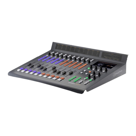
Eclipse is a powerful live mixing and recording console with the
flexibility to adapt to Front of House (FOH), Monitors or OB van
applications.
Control Surface Overview
Fader Strips
The lower half of the Eclipse control surface features 48 Fader
strips each with its own VU meter, rotary control (gain, trim, pan
or user), Label, ID, MUTE, CUE and fader select (SEL) button.
Faders are touch-sensitive and motorised. Each is clearly
labeled with a 4-character user name and colour coded ID. The
IDs enable you to glance across the console and easily
distinguish Inputs (blue) from Auxes (green), VCAs (yellow),
Masters (red), Matrix outputs (violet), etc.

Chapter 1: Overview
Control Surface Overview
10/ 380 V1.0/1 Eclipse User Guide
Smart Panel “Strips”
Above Fader strips 14 to 20 you will find the SMART PANEL.
This provides 48 additional control strips available in 4 layers:
A, B, C and D.
Each Smart Panel strip features the same functionality as a
Fader strip, except level and cue are adjusted by a rotary
control, and there is no Gain/Trim/Pan control.
As for the Fader strips, the colour coded IDs allow you to
glance at the Smart Panel to see whether its controllers are
assigned to Auxes, Matrix outputs, additional Inputs, etc.
Selected Channel Control
To the left of the SMART PANEL are the INPUT, DELAY,
DYNAMIC, PARAM EQ and PAN sections. Together these form
a “channel strip” for the selected Fader or Smart Panel strip:
Once a SEL button is active (flashing), these panels offer direct
control of all settings – gain, insert switching, low cut filter,
delay, dynamics, equalisation and panning. The controls work
in conjunction with the Main Mix display which provides
graphical feedback on the selected channel:

Chapter 1: Overview
Control Surface Overview
Eclipse User Guide V1.0/1 11/ 380
Utilities
Above the PARAM EQ is a UTILITIES panel with access to a
range of functions:
•Flat – resets the Gate, Compressor, Parametric EQ or
Graphic EQ section on the selected (SEL) channel.
•Copy Paste – used to copy parameters from the
selected channel to other channels.
•Over Ram – writes parameters from the selected
channel into other Pages (snapshots). For example, to
overwrite a new mic gain into all the Pages for a show.
•Relax – isolates parameters so that they are not reset
by a Page load. For example, if you are using Pages to
recall a different mix for each song, you might Relax the
vocal faders so that there are no sudden jumps in level.
•Rqst – turns the channel select (SEL) buttons into on/off
buttons for a requested parameter. For example, to turn
EQ on or off across multiple channels.
•Pre/Pan – provides an overview of bus routing from the
selected channel (or to the selected output), with options
to configure pre-fader or independent pan bus sends.
•Link Cards – links I/O parameters on an input or output
card. For example, to link mic preamp gain on input
cards, or to link output processing on output cards.
User Defined Panel
The USER DEFINED panel provides six VU meters, four rotary
controls and four switches.
In Version 1 software, these controls have fixed functions. In
future releases, they may be defined by the user.

Chapter 1: Overview
Control Surface Overview
12/ 380 V1.0/1 Eclipse User Guide
Nova Touch-Screen
The console screen is a touch-screen display which provides
access to Nova, the name given to Eclipse’s management
software.
Nova is designed to provide you with the maximum amount of
information on the state of your mix during a live show; this
display is called the Main Mix. In addition, a number of other
displays provide access to console configuration, patching, etc.
A trackball is situated to the right of the touch-screen and the
console keyboard, with its own trackball, pulls out from the front
drawer. Many functions can be selected either by touching the
screen, using the trackball, or pressing a keyboard shortcut key.
Nova may be used offline on any PC running Windows XP. You
can prepare configurations in advance and then load them to
the console when you arrive at a venue.
USB Port and Timecode Display
Directly to the left of the touch-screen is a USB port where you
can import or export user settings or install new software. To
the left of this is a timecode display for either the integrated
M.A.R.S. hard disk recorder or external MIDI timecode.
PSU Status Indicators
To the right of the touch-screen are a row of LEDs indicating
the status of power supplies (A and B) and internal voltages.
M.A.R.S. Control Panel
Below the touch-screen is the M.A.R.S. control panel
(Multitrack Audio Recording System) which will be implemented
in a future release of software and hardware.
M.A.R.S. will provide 64 tracks of integrated hard disk
recording, allowing playback of sound checks at different
venues without the band being present.

Chapter 1: Overview
Control Surface Overview
Eclipse User Guide V1.0/1 13/ 380
TB/Monitoring
To the right of the touch-screen are the console’s talkback,
monitoring and headphone controls.
Eclipse includes a stereo monitor bus which may be switched to
three different monitor outputs. In addition, a headphone output
is provided at the front of the console (1/4” jack).
The console’s CUE buttons may operate as AFL, PFL or Solo-
in-Place (SIP).
Talkback may be switched to three different outputs. A talkback
microphone input is provided at the front of the console (XLR).
Utilities
A second UTILITIES panel provides access to:
•Off Line Mode – you can use this mode to load Pages
to the console to check or modify settings without
affecting the current mix.
•Play List – the Play List manages Page automation. For
example, to change the order of Pages for the show, to
set crossfade times between Pages, etc.
•Test – routes the Oscillator test tone to the selected
channel.
•D I/O – displays the PATCH DIRECT grid.
•Patch IN – displays the PATCH IN grid.
•Patch OUT – displays the PATCH OUT grid.
Files/Auto
The FILES/AUTO panel provides buttons for saving settings
(Files) and managing console automation (Pages).
Trackball and Keyboard
To the left of the FILES/AUTO panel you will find a trackball
with left and right “mouse” buttons, and OK and CANCEL.
The console keyboard is located in a pull-out drawer at the front
of the desk. A second trackball is included with the keyboard for
convenience.

Chapter 1: Overview
System Overview
14/ 380 V1.0/1 Eclipse User Guide
System Overview
Unlike an analogue console, Eclipse consists of much more
than just the operating surface; a system may incorporate three
principle components:
•Console – includes the console’s DSP processing and
master control, six slots for local i/o and internal effects
cards, and an internal PC running the Nova application
software.
•DioCore – an external unit connected to the console via
Ethersound, offering up to eight slots for input and
output cards. The DioCore may be located up to 100m
from the console on coax (CAT5) connection.
•Muxipaire Stagebox (optional) – an external unit
connected to the console via Innovason’s Muxipaire
interface (coax or fibre). This Stagebox works in parallel
with the six i/o and effects slots in the rear of the
console, providing a way to remote additional i/o onto
the stage if required.

Chapter 1: Overview
System Overview
Eclipse User Guide V1.0/1 15/ 380
I/O and FX Cards
The six slots at the rear of the console (or in a Muxipaire
Stagebox) and the eight slots in a DioCore may be fitted with
any combination of the following I/O :
•SI-8D3 – 8 mic/line inputs (on 8 balanced XLRs).
•DI-8S – 4 AES inputs (8 mono channels on 4 balanced
XLRs).
•DI-8Src – 4 AES inputs with sample rate conversion (8
mono channels on 4 balanced XLRs accepting sample
rates from 32kHz to 56kHz).
•UM-8PO - 8 analogue line outputs (on 8 balanced
XLRs). Each pair of outputs may be switched to AES. All
8 outputs are also available as ADAT via a TOSlink
connector. Each output has its own signal processing
(Compressor, Gate, 8-band Parametric EQ, 31-band
Graphic EQ and Delay.) Note that the UM-8PO is not
recognised in a Muxipaire Stage-Box. Use the MO-8D3
for this external audio rack.
The internal effects card can be fitted only in the rear of the
console :
•FM-8VB – 8 channels of internal effects. Each pair of
channels may be linked for stereo operation. Each
channel has 4 effects engines which may operate a VB
Audio plug-in (Reverb, Echo, Chorus, Flanger, De-
esser, Compressor, Gate, Multiband Compressor, etc.)
Note that all cards operate at 24-bit, 48kHz. (If the system is
synchronised to an external clock signal, then the sampling
frequency may operate from 43-49kHz).
The Standard Eclipse I/O Package
So that you know what to expect, particularly when arriving to
work on a rental console, Eclipse is delivered with a standard
package of i/o and internal effects cards which consists of:
•1 DioCore – remote stage i/o with:
o7 SI-8D3 cards = 56 Mic Preamps
o1 UM-8PO card = 8 Outputs (Line/AES/ADAT)
•Console - local desk i/o of:
o1 SI-8D3 card = 8 Mic Preamps
o2 UM-8PO cards = 16 Outputs (Line/AES/ADAT)
o2 FM-8VB = 16 mono effects bays
o16 Line Inputs and 16 Line Outputs
You can find more details in Chapter 2: Installation.

Chapter 1: Overview
System Overview
16/ 380 V1.0/1 Eclipse User Guide
Audio Networking
Ethersound is an open protocol offering 64-channels of
bidirectional i/o via a CAT5 cable (up to 100m). Multiple
DioCores may be connected to the Ethersound network in order
to distribute i/o to different physical locations.
Note that up to 4 DioCores may be active on each console at
any one time. The console operator may then select which 64-
channels of i/o they wish to use from the Ethersound network.
In addition, Ethersound may be used to link I/O between
consoles. The example below shows two Innovason consoles
sharing resources from two DioCores:
If more than 64 inputs and 64 outputs are required on stage,
then an additional remote unit (the Muxipaire StageBox) may be
added. This StageBox works in parallel with the six i/o and
internal effects slots at the rear of the console. So, in order to
add i/o to a StageBox, you may need to remove local i/o from
the console:
You can find more details on DioCore networks and the
Muxipaire Stagebox on Page 232.

Chapter 1: Overview
Signal Flow
Eclipse User Guide V1.0/1 17/ 380
Signal Flow
The console is equipped with a DSP engine which enables you
to mix up to 104 input channels simultaneously onto 48 mix
busses.
Each Input channel provides:
•Analogue input control (preamp gain and 48V)
•Digital input control (digital gain trim and phase reverse)
•A Low Cut Filter
•Dynamics (independent Gate and Compressor)
•Delay – assignable from a pool of 48 delay resources.
•Parametric EQ (4-band)
•Pre-fader Insert (external device or internal effects bay)
•Pan
•Main level, Mute and Cue
•Aux Send Level (pre-fader, post-fader or independent)
•Matrix Send Level (pre or post-fader)
Each mix bus may be configured as an Aux, Group, Master or
Matrix output, allowing you to build your console signal flow to
meet each show’s requirements:

Chapter 1: Overview
Signal Flow
18/ 380 V1.0/1 Eclipse User Guide
Auxes, Groups and Masters may be mono, stereo, LCR or
LCRM; Matrix busses are always mono. Note that a stereo Aux
uses two mix bus resources; a 4-channel Master uses four mix
bus resources; and so on.
To apply signal processing to a mix bus you can either insert
one of 16 internal “floating” DSP paths, or route the bus to a
physical output. Every output of a UM8-PO card provides output
processing (Compressor, Gate, 8-band Parametric EQ, 31-
band Graphic EQ and Delay).
Note that there is an important difference between inserting
DSP and using a processed output. Inserted processing is
applied to everything downstream of the mix bus channel,
whereas UM8 processing applies to the physical output. This
allows you to patch say a single Matrix bus to multiple outputs
each with its own delay tim9nh 1e’/e, graphic EQ, etc.
The following diagram shosws the division between processing
on the I/O cards and processing on Eclipse’s DSP module:
Note that in addition to the 48 configurable mix busses, a stereo
bus is included for monitoring.
You can find more details on Input channels on Page 108, Mix
Busses on Page 135, Output channel processing on Page 151,
and Monitoring on Page 182.

Chapter 1: Overview
Channel Types
Eclipse User Guide V1.0/1 19/ 380
Channel Types
Eclipse has 48 Fader Strips plus 48 Smart Panel controllers
(available in 4 layers: A, B, C and D).
Each may control any of the following channel types allowing
you to lay out your source channels, bus masters and VCAs
where you want them:
•Input channel – direct control of one of your 104 input
channels.
•Output channel – direct control of an Aux, Group,
Master or Matrix mix bus output (up to 48 mix busses).
•VCA – master control of level and mute for several input
and/or output channels.
•Smart Fader (SFAD) – “layered” control of several input
channels from a single fader. See the next page for
details.
•Smart Bus Fader (XBus) – “layered” control of the Left,
Centre, Right and Mono channels of a stereo/multi-
channel Aux or Group mix bus.
•Monitoring Level – control of monitor output level. You
can use this option to control monitor level from a fader
rather than the TB/MONITORING panel.
•Crossfade Time – control of the transition time between
Pages when using automation.
This flexibility allows you to customise the console surface for
each show and for different applications.
The configuration of Fader Strips and Smart Panel Controllers
is handled by Nova’s Personal Console Builder, see Page
198 for details.

Chapter 1: Overview
Smart Faders (SFADs)
20/ 380 V1.0/1 Eclipse User Guide
Smart Faders (SFADs)
So far we have described how any input may be controlled
directly from a Fader Strip or Smart Panel controller. However,
in order to manage larger shows where the number of sources
may exceed your physical faders, Eclipse provides a unique
“layering” solution – Smart Faders (SFADs).
This solution works by using a Smart VCA (SVCA) to control a
number of Input slave channels. Each time you press the SEL
button on the Smart VCA, its slaves are deployed to a pre-
defined zone on the console (SZONE), thereby controlling
multiple sets of “layered” Inputs from very few physical faders:
By configuring multiple Smart VCAs the layout of the desk can
be customised to handle complex show configurations.
For more details on Smart Faders, see Page 124.
Other manuals for Eclipse
1
Table of contents
Other INNOVASON Music Mixer manuals

