Innovatech P32NDX User manual

INNOVATECH PRODUCTS 832 80th St SW, Everett, Washingt n, USA 98203
Teleph ne: 1-425-405-9100 T ll Free: 1-800-267-6682 Fax: 1-425-405-9108
PREDATOR GRINDER POLISHER
P32NDX – P32ND
OWNER’S MANUAL
Orig. Rel. – 09/2015
Curr Rev. - 00

P32NDX – P32ND OWNER’S MANUAL
1
ORIGINAL LANGUAGE
OPERATING MANUAL
FOR
P32NDX & P32ND GRINDER POLISHER
© 2015 Innovatech Products
N part f this w rk may be repr duced r transmitted in any f rm r by any means, electr nic
r mechanical, including ph t c pying and rec rding, r by any inf rmati n st rage r retrieval
system with ut the pri r written permissi n f Inn vatech unless such c pying is permitted by
federal c pyright laws.
Address inquiries r reference permissi ns care f:
Inn vatech Pr ducts, 832 80th St SW, Everett, Washingt n, USA 98203
REV
.
DATE
DESCRIPTION
APPROVED BY:
Bart ll Morrison Inc.
375 Annagem B ulevard
Mississauga, Ontari , Canada
L5T 3A7
Tel: (905) 364-4200
T ll Free: (866) 501-1683
Fax: (905) 364-4201
SPE Int rnational Ltd
H neyh les Lane
Dunh lme, Linc ln, England
LN2 3SU
Tel: 01673 860709
Fax: 01673 861119
Bart ll Morrison USA LLC
200 C mmerce Drive, Unit A
Freeh ld, NJ, USA
07728
Tel: (732) 566-5400
T ll Free: (888) 999-1570
Fax: (732) 566-5444
Innovat ch
832 80th Street SW
Everett, Washingt n, USA
98203
Tel: (425) 905-9100
T ll Free: (800) 267-6682
Fax: (425) 405-9108
BARTELL
P32NDX – P32ND OWNER’S MANUAL
2
SAFETY PRECAUTIONS
DANGER
EXPLOSION HAZARD
Never perate the machine in an expl sive
atm sphere, near c mbustible materials, r
where ventilati n d es n t clear exhaust fumes.
WARNING
BURN HAZARD
Never c me int c ntact with the engine r
muffler when engine is perating r sh rtly after it
is turned ff. Seri us burns may ccur.
CAUTION
MOVING PARTS
Bef re starting the machine, ensure that all
guards and safety devices are in place and
functi ning pr perly.
ATTENTION
READ OWNER’S MANUAL
Read and understand wner’s manual bef re
using this machine. Failure t f ll w perating
instructi ns c uld result in seri us injury r death.

P32NDX – P32ND OWNER’S MANUAL
3
TABLE OF CONTENTS
INTRODUCTION 4
SPECIFICATIONS 4
WARRANTY INFORMATION 5
SAFETY PRECAUTIONS 7
OPERATION INSTRUCTIONS 8
MAINTENANCE 9
TROUBLESHOOTING 9
FAULTS WHICH CANNOT BE AUTOMATICALLY RESET 10
PARTS DRAWINGS & DIAGRAMS 12
BELT
TENSIONING
GUIDE
14
BELT
ROUTING
PATH
16
DECLARATION OF CONFORMITY 22

P32NDX – P32ND OWNER’S MANUAL
4
INTRODUCTION
Inn vatech Pr ducts and Equipment C mpany specializes in the manufacturing and distributi n
f surface preparati n equipment and supplies. Fr m ur early rigins as a fl ring rem val
c mpany, and a f undati n based up n the success f ur Terminat r line f fl ring rem val
machines, Inn vatech has transf rmed itself int an industry leader ver a twelve year peri d.
Our c ntinued gr wth can be attributed t ur pledge t ffer nly premium pr ducts, ur
c mmitment t stand behind what we sell, and a staff well kn wn thr ugh ut the industry f r
their kn wledge and c mmitment t ur valued cust mers. Based n cust mer need,
Inn vatech has pr udly diversified ur fferings t include a c mplete line f surface
preparati n pr ducts including Sh t Blasters, Scarifiers, Fl r Grinders, Dust C llect rs,
Diam nd Abrasives, and ther pr ducts.
SPECIFICATIONS
P32NDX
P32ND
Cutting Width
32” (812mm) 32” (812mm)
Dim nsions
(Op rating
Conditions)
82” x 34” x 52”
(2083mm x 864mm x
1320mm)
82” x 34” x 52”
(2083mm x 864mm x
1320mm)
W ight
1181lbs (536kg) 950lbs (431kg)
Tank Capacity
7 Gal (27L) 7 Gal (27L)
Cutt r H ads/Tool Plat s
Diameter 10.5” (270mm) 10.5” (270mm)
RPM 0 – 1010rpm 0 – 1010rpm
Motor
15hp (11kW) - 0 – 1760rpm
20hp (15kW) 0 – 1760rpm 0 – 1760rpm
Pow r Sourc
Phase 3 Phase 3 Phase
V ltage 414 – 504V 414 – 504V
Hz 60Hz 60Hz
Amps 29A 25A

P32NDX – P32ND OWNER’S MANUAL
5
WARRANTY INFORMATION
Inn vatech warrants t riginal retail purchaser f the equipment:
A. LIMITED WARRANTY
The equipment, when first delivered, will c nf rm t the specificati ns set f rth in the
Owner’s Manual and will be with ut defect in material r w rkmanship. F r a peri d f
ne (1) year after delivery t the riginal retail purchaser, r 300 cl ck h urs f
perati n, whichever ccurs first; r in the case f replacement parts ther than belts, f r
a peri d f ninety (90) days after the part is installed r within the warranty peri d
described ab ve, whichever is later, if the riginal retail purchaser n tifies Inn vatech
(either directly r thr ugh ne f Inn vatech’s auth rized dealers) f a defect in material
r w rkmanship r f a n n-c nf rmity t the specificati ns, then, up n c nfirmati n f
the defect f n n-c nf rmity and c nfirmati n that the defect r n nc nf rmity is c vered
within these Limited Warranty c nditi ns, Inn vatech will, at it’s electi n and at it’s
expense, either (i) repair r c rrect the defect and/ r n n-c nf rmity, r (ii) replace the
part.
B. LIMITATIONS
This Limited Warranty d es n t apply t damage caused by (i) misuse f the equipment
including, with limitati n, use f the wr ng p wer s urce, striking an imbedded bject
such as a b lt, electrical utlet b x, expansi n j int r steel reinf rcing r d; r (ii)
unauth rized alterati n, m dificati n, repair r tampering; r (iii) use f replacement
parts n t supplied by Inn vatech; r (iv) n rmal wear, disc l rati n, surface c rr si n,
deteri rati n f finishes r paint surfaces, r (v) ther appearance deteri rati n caused
primarily by use. Inn vatech shall n t be resp nsible and this Limited Warranty shall n t
apply t damage caused by impr per maintenance r failure t inspect and maintain the
equipment as rec mmended in the Owner’s Manual.
C. BELTS
The Drive Belt is c vered as set ut at paragraph A., ab ve, but f r the peri d f six (6)
m nths after delivery r 250 cl ck h urs f perati n, whichever ccurs first.
D. TRANSPORTATION
Purchaser will pay the c st f transp rting defective r n n-c nf rming parts t
Inn vatech and the c st f returning repaired r replacement parts t purchaser. Each
party will safely package the parts it sends t the ther in acc rdance with g d
c mmercial practice. If purchaser requests and Inn vatech agrees, Inn vatech may
perf rm c vered warranty w rk where the equipment is l cated. If Inn vatech perf rms
the w rk at the l cati n, purchaser will pay the c st f business class transp rtati n and
g d quality meals and l dging f r Inn vatech’s technicians.
E. ABUSE
Inn vatech is n t resp nsible f r damage, defect, breakage, r malfuncti n f the
equipment that is caused by abuse r by perati n f the equipment in a manner which
is n t rec mmended r appr ved by Inn vatech.
F. EXCLUSIVE WARRANTY
Except as is expressly set ut in this limited warranty: (i) Inn vatech makes n pr mise
r warranty, expressed r implied, with respect t the equipment; (ii) Inn vatech makes
n pr mise r warranty that the equipment is fit f r any particular purp se; (iii)
Inn vatech will have n bligati n r liability t the purchaser r t any third party with f r

P32NDX – P32ND OWNER’S MANUAL
6
any damage caused by the equipment r as a result r c nsequence f any claimed
defect in the equipment, any failure t warn r n tify, r any claimed n n-c nf rmity t
the specificati ns; and (iv) Purchaser will have n ther remedies in respect f such
defect, n n-c nf rmity, damage r c nditi n except th se set ut in this limited warranty.
With ut limiting the f reg ing, and regardless f the circumstances and even if a remedy fails,
Inn vatech will have n liability t the purchaser r t any third party f r (i) l ss f revenue r
pr fits, r (ii) f r incidental, c nsequential, r punitive damages.

P32NDX – P32ND OWNER’S MANUAL
7
SAFETY PRECAUTIONS
1. Only pers ns wh have received training are permitted t perate r repair the grinder.
2. Use pers nal safety equipment such as steel t e sh es, safety glasses, and earplugs.
3. D n t use grinder in area where there is a risk f expl si n r fire.
4. D n t start the machine with heads ff the gr und.
5. Make sure the splashguard is n bef re stating machine.
6. Bef re y u start grinding, check the fl r f r b lts, large h les and uneven j ints. Hitting
these things can damage machine, t ls, and cause pers nal injury.
7. Make sure all p wer supply is c nnected with the right v ltage.
8. Use nly c ld water in water tank. D n t use chemicals in water tank.
9. When filling water tank, t av id electrical hazards and injury, d n t spill water nt the
machine m t r and electrical b x.
10. Switch ff the machine p wer bef re changing grinding t ls.
11. Disc nnect p wer supply bef re w rking r repairing machine.
12. Be very careful with r lling machine n any sl ping fl rs r ramps. The machine can r ll
very quickly. Tw pe ple may be needed t handle and c ntr l the machine.
13. Use cauti n with rem ving the grinding t ls after finished grinding. T ls can be very
h t. Use gl ves t rem ve the plates.
14. When grinding glues, ep xy paints, r c atings, leaving the machine d wn n fl r c uld
cause the head t stick t the fl r. Always tip back machine as s n as the head c mes
t a c mplete st p.
15. Always st re machine in a dry place.
16. Only use Inn vatech rec mmended t ling.
17. The perat r must never leave the machine unattended during perati n.
18. When grinding dry, use a suitable vacuum t extract the dust.
19. Inn vatech is n t resp nsible f r any ff gassing f hazard us gas that is generated by
grinding materials. It is the resp nsibility f the perat r. Grinding fl rs c ntaining
asbest s is especially danger us and can cause health pr blems. C ntact y ur state r
c untry f r the pr per way t handle it.

P32NDX – P32ND OWNER’S MANUAL
8
OPERATION INSTRUCTIONS
Bef re starting:
1. Check the fl r carefully and rem ve all b lts, nails, as well as any l se material that
c uld get caught in the machine.
2. Fit the appr priate t ls t the machine.
3. Fit splash guard t the right height.
4. C nnect the p wer supply. Make sure y u have all the phases. May have t check with
v lt meter.
5. If y u are grinding dry, c nnect the appr priate vacuum and start vacuum bef re starting
the grinder.
Starting machine:
1. Turn main p wer switch n side f p wer b x t ON.
2. Turn f rward r reverse switch left f right.
3. Turn manual speed p t up t get the heads turning f r desired speed. (If heads d n t
m ve, y u may have t lean n handle t reduce pressure n t ls.
4. Always grip handle firmly when starting machine. The machine will always m ve fr m
side t side with first start.
5. When finished with grinding, turn ff machine and let the heads c me t a c mplete st p
bef re tilting back the machine.
Changing f T ls:
1. Bef re w rking n the grinder, bring the m t r t a t tal st p and disc nnect p wer.
2. Tilt machine back n fl r.
3. Use cauti n! T ls can be very h t fr m grinding. Use gl ves.
4. Use special t l supplied t turn center f t l h lder t rem ve t l plate.
5. Replace with new t l plate and turn t l ck in place.
6. L wer machine back d wn and re-adjust splash guard is necessary.
NOTE:
IF THE WRONG POWER IS SUPPLIED TO THE GRINDER, IT WILL DAMAGE
THE ELECTRICAL COMPONENTS IN THE INVERTERS.

P32NDX – P32ND OWNER’S MANUAL
9
MAINTENANCE
Clean machine after every use. T clean machine, use a l w pressure water h se r air
pressure. D n t use a high PSI pressure washer. This c uld f rce water int areas f the
machine unintenti nally and damage parts. A regular inspecti n f machine f r wear and
damage sh uld be d ne n a regular basis. If any parts have been damaged r have excessive
wear, they sh uld be replaced. If belt is in need f being replaced, please see separate
instructi ns.
TROUBLESHOOTING
1. Check t see if main p wer supply is n.
2. Check t see if emergency st p is pushed d wn; if it is, pull up.
3. Check t see if manual speed p t is turned up past 1.
4. Check all c rds ends f r l se c nnecti n.
5. Check fuse in distributi n b x with test meter.
6. Check t see if all phase are with right v ltage (check with v lt meter).
7. Check the c nverter c nnect r cable t m t r.
8. Check f r err r message n display f the c nverter.

P32NDX – P32ND OWNER’S MANUAL
10
FAULTS WHICH CANNOT BE AUTOMATICALLY RESET
Faults which cann t be aut matically reset are listed in the table bel w. T clear these faults:
1. Rem ve p wer fr m the drive c ntr ller.
2. Wait f r the display t g ff c mpletely.
3. Determine the cause f the fault and c rrect it.
4. Re-apply p wer.
FAULT
PROBABLE CAUSE
REMEDY
B L F
Brake Sequence
• Brake release current n t reached • Check the drive c ntr ller and m t r
c nnecti ns
• Check the m t r windings
C r F
Precharge Circuit
Fault
• Precharge circuit damaged • Reset the drive c ntr ller
• Replace the drive c ntr ller
I n F
Internal Fault
• Internal fault
• Internal c nnecti n fault
• Rem ve s urces f electr magnetic
interference
• Replace the drive c ntr ller
O C F
Over Current
• Inc rrect parameter settings in the
Set- and drC- menus
• Accelerati n t rapid
• Drive c ntr ller and/ r m t r
undersized f r l ad
• Mechanical bl ckage
• Clear the mechanical bl ckage
S C F
M t r Sh rt Circuit
• Sh rt circuit r gr unding at the drive
c ntr ller utput
• Significant gr und leakage current at
the drive c ntr ller utput if several
m t rs are c nnected in parallel
• Check the cable c nnecting the drive c ntr ller
t the m t r and check the m t r insulati n
• Reduce the switching frequency
S O F
Over Speed
• Instability
• Overhauling l ad
• Check the size f the m t r, drive c ntr ller,
and l ad
F n F
Aut-Tuning Fault
• M t r r m t r p wer n t suitable f r
the drive c ntr ller
• M t r n t c nnected t the drive
c ntr ller
• Check the presence f the m t r during aut -
tuning
• If a d wnstream c ntract r is being used, cl se
it during aut -tuning
E P F
External Fault
• User defined • User defined
L F F • L ss f the 4-20 mA reference n
input A13
• Check the c nnecti n n input A13
• L ss f 4-20 mA f ll wer
O b F
Over v ltage during
decelerati n
• Braking t rapidly
• Overhauling l ad
• Increase the decelerati n time
O H F
Drive Overl ad
• Drive c ntr ller r ambient
temperature is t high
• C ntinu us m t r current l ad is t
high
• Check the m t r l ad, the drive c ntr ller
ventilati n, and the envir nment. Wait f r the
drive c ntr ller t c l bef re restarting
O L F
M t r Overl ad
• Thermal trip due t pr l nged m t r
verl ad
• M t r p wer rating t l w f r the
applicati n
• All w the m t r t c l bef re restarting
O P F • L ss f phase at drive c ntr ller • Check the c nnecti ns fr m the drive c ntr ller

P32NDX – P32ND OWNER’S MANUAL
11
M t r phase failure utput
• D wnstream c ntract r pen
• M t r n t c nnected
• Instability in the m t r current
• Drive c ntr ller versized f r m t r
t the m t r
• Test the drive c ntr ller n a l w p wer m t r
r with ut a m t r: set OPL t nO
O S F
Over v ltage during
steady state
perati n r during
accelerati n
• Line v ltage t high
• Line supply transients
• Check the line v ltage. C mpare with the drive
c ntr ller nameplate rating
• Reset the drive c ntr ller
P H F
Input phase failure
• Input phase l ss, bl wn fuse
• Three-phase drive c ntr ller used n
a single-phase line supply
• Input phase imbalance
• Transient phase fault
NOTE: This protection only operates
with the drive controller running under
load
• Check the c nnecti ns and the fuses
• Verify that the input p wer is c rrect
• Supply three-phase p wer if needed
C F F
C nfigurati n Fault
• The parameter c nfigurati ns are n t
suited t the applicati n
• Rest re the fact ry settings r l ad the backup
c nfigurati n, if it is valid
U S F
Under V ltage
• Line supply t l w
• Transient v ltage dip
• Damaged precharge resist r
• Check the line v ltage
• Replace the drive c ntr ller

P32NDX – P32ND OWNER’S MANUAL
12
PARTS DRAWINGS & DIAGRAMS

P32NDX – P32ND OWNER’S MANUAL
13

P32NDX – P32ND OWNER’S MANUAL
14
BELT TENSIONING GUIDE
18
6
15
10
3
11
7
1
17
8
16
12
2
5
49
SEE
NOTE 3
SEE
NOTE 3
14
SEE
NOTE 4
SEE
NOTE 5
SEE
NOTE 6
TAPPED
HOLE
TYP 2 PL
CUTTER HEAD PULLEY
BOTTOM END
NOTES:
1. FOR ILLUSTRATION SIMPLICITY NOT ALL ITEMS ARE EXPLODED,
BUT ARE REPRESENTED BY THEIR SAME-NATURE COUNTERPART.
2. SOME PARTS MAY BELONG TO ANOTHER COMPONENT GROUPING
OR INSTALLATION SEQUENCE, BUT SHOWN HERE FOR DETAILED
ASSEMBLY INFO.
3. ADD SHIM(S) [PART # 11-0325, QTY AS NEEDED] TO INDICATED
SCREWS FOR PROPER CLEARANCE WITH MATING PART.
4. COMPRESSED SPRING SHOULD HAVE FINAL LENGTH OF APPROX.
1-1/16" (27mm).
5. MOTOR PART #: P32NDX: 23-0099 (20HP), P32ND: 23-0039 (15HP).
6. USE INDICATED SETS OF PIN HOLES FOR MOUNTING FLOATING
HEAD TOOL PLATES. RESERVE REMAINING HOLES FOR RIGID HEADS.
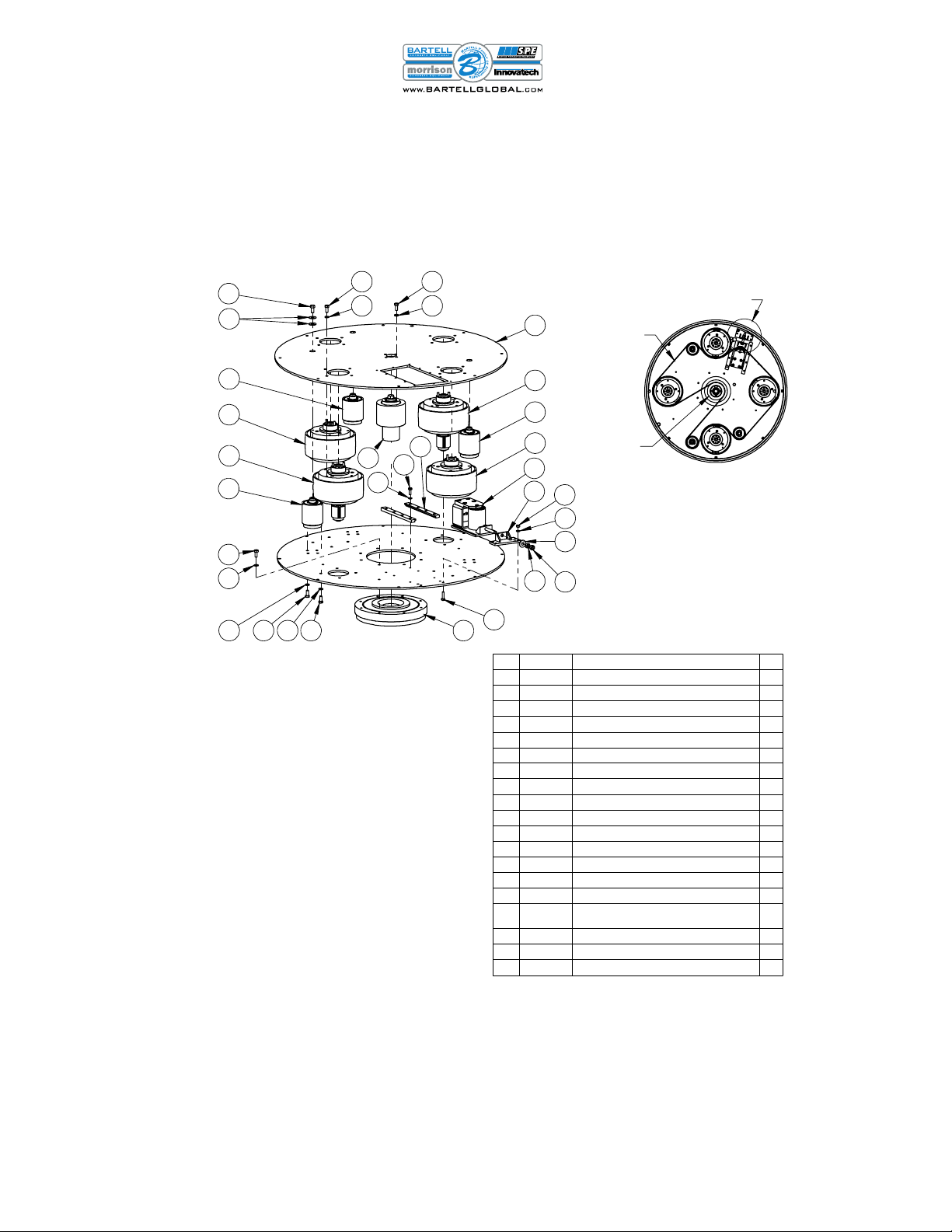
GRINDER HEAD (WITHOUT SHROUD) - P32 "ND" SERIES
ITEM PART # DESCRIPTION QTY
1 11-0035 Washer, 3/8" 2
2 11-0040 Split l ck washer, 5/16" 6
3 11-0124 Nut, 3/8"-16 2
4 11-0129 Split l ck washer, 3/8" 2
5 11-0132 Hex head cap screw, 5/16"-18 x 1" 6
6 11-0136 Hex head cap screw, 3/4"-10 x 2" 4
7 11-0256 Hex head cap screw, 3/8"-16 x 3" 2
8 11-0287 Sh ulder screw, 3/8 dia. x 3/8 L
sh ulder, 5/16"-18 threads 2
9 11-0324 Sh ulder screw, 3/8 dia x 1/4 L
sh ulder, 5/16"-18 threads 2
10 13-0125 V-ring seal, 225 ID x 15 W 1
11 13-0266 Spring 2
12 51-0048 Spacer ring 1
13 51-0875 Drum driver anch r 2
14 96-0027 Cutter head- Fl ating assy 4
15 96-0279 M t r base assy 1
16 96-0280 Drum assy 1
17 96-0283 Drum driver unit 2
18 see n te Electric m t r 1

P32NDX – P32ND OWNER’S MANUAL
15
5
3
8
7
4
6
9
1
3
2
DRUM DRIVER UNIT - P32 "ND" SERIES (#96-0283)
ITEM PART # DESCRIPTION QTY
1 11-0069 Split l ck washer, 1/4" 3
2 11-0349 Butt n head s cket cap screw, 1/4"-20 x 5/8" 3
3 13-0207 Bearing (30 ID x 47 OD x 9 W) 2
4 13-0212 Y ke end, 3/8"-16 theads, 3/8 pin h les 1
5 13-0334 O-ring, 1.125 ID x .094 W 1
6 13-0335 Spring, .39 ID x .48 OD x .75 l ng 1
7 51-0846 Gear pulley 1
8 51-0864 Tensi ner t p plate 1
9 53-0302 Tensi ner base build-up 1
7
5
4
6
2
1 3
SEE
NOTE 1
NOTES:
1. GRINDER HEAD UNIT PART # :
P32NDX: 96-0277 (20 HP). P32ND: 96-0323 (15 HP).
GRINDER HEAD (WITH SHROUD) - P32 "ND" SERIES
ITEM PART # DESCRIPTION QTY
1 11-0069 Split l ck washer, 1/4" 12
2 11-0234 Hex head cap screw,
1/4"-20 x 2" 12
3 11-0259 Flat washer, 1/4" 12
4 54-0027 Splash guard 1
5 54-0039 Shr ud (cut- ut panel) 1
6 96-0278 Shr ud (main c ver) 1
7 see n te Grinder head 1
P32NDX – P32ND OWNER’S MANUAL
16
BELT ROUTING PATH
8
14
13
6
7
12
5
3
16
2
4
15
2 4 2 4
3
1
7
15
1
4
2
4
2
15
19
11
SEE
NOTE 3
SEE
NOTE 4
SEE
NOTE 2
9
18
17
18
17
BELT (13-0138)
SEE NOTE 5
SEE NOTE 6
BELT ROUTING
CENTER
DRIVE
PULLEY
NOTES:
1. DRUM TOP AND BOTTOM PLATES ARE COMPONENTS OF DRUM
ENVELOPE. FOR ILLUSTRATION CLARITY OF HOW PARTS FIT
TOGETHER, NOT ALL OF DRUM ENVELOPE'S PARTS ARE SHOWN.
2. INDICATED WASHER FOR IDLER INSTALLATION IS MANDATORY
TO ENSURE SCREW END'S CLEARANCE WITH NEARBY ROTATING
BEARINGS.
3. STACKING OF INDICATED WASHERS REQ'D FOR STRENGTH.
4. SECURE INDICATED SCREW WITH MEDIUM STRENGTH THREAD
LOCKING COMPOUND.
5. DRIVE BELT NOT SHOWN IN EXPLODED VIEW FOR ILLUSTRATION
SIMPLICITY. BELT'S ROUGH (GRAY COLORED) SIDE TO FACE /
CONTACT CENTER DRIVE PULLEY.
6. TIGHTEN/TENSION BELT UNTIL CLEARANCE BETWEEN END OF
TENSION SCREW AND DRUM SIDE WALL IS APPROX. 1/16" (1 - 2mm).
DRUM ASSEMBLY - P32 "ND" SERIES (#96-0280)
ITEM PART # DESCRIPTION QTY
1 11-0035 Washer, 3/8" 7
2 11-0040 Split l ck washer, 5/16" 72
3 11-0069 Split l ck washer, 1/4" 2
4 11-0118 Hex head cap screw, 5/16"-18 x 3/4" 5
5 11-0121 Hex head cap screw, 1/4"-20 x 1" 4
6 11-0123 Nut, 1/4"-20 4
7 11-0124 Nut, 3/8"-16 2
8 11-0130 Hex head cap screw, 3/8"-16 x 3/4" 3
9 11-0279-12 Hex head cap screw, 1/4"-20 x 3/4", Gr.8 6
10 13-0138 Belt 1
11 51-0014 Tensi ner sliding track 2
12 53-0017 Tensi ner anch r 1
13 96-0012 Tensi ner Sliding Unit 1
14 96-0018 Pulley (center drive) assy 1
15 96-0019 Idler (main drive) assy 3
16 96-0022 Bearing assy (m t r base / drum
c nnecti n) 1
17 96-0281 Cutter head pulley assy (with t p pulley) 2
18 96-0282 Cutter head pulley assy (with ut t p pulley) 2
19 96-0285 Drum envel pe 1
P32NDX – P32ND OWNER’S MANUAL
17
5
2
1
3
4
10
9
6
11
8
7
1
3
SEE
NOTE 1
SEE
NOTE 2
SEE
NOTE 3
10
38
6
9
2
4
11
12
7
1
5
SEE NOTE 1
SEE NOTE 2, 3
SEE NOTE 3
SEE NOTE 3
NOTES:
1. INDICATED SCREW TO BE USED FOR ATTACHING
ASSEMBLY TO CUTTER HEAD PULLEY'S SHAFT.
2. WASHERS DOUBLED UP FOR STRENGTH.
3. SECURE INDICATED SCREW(S) WITH MEDIUM
STRENGTH THREAD LOCKING COMPOUND
(E.G. LOCTITE 242). TYP 3 PL.
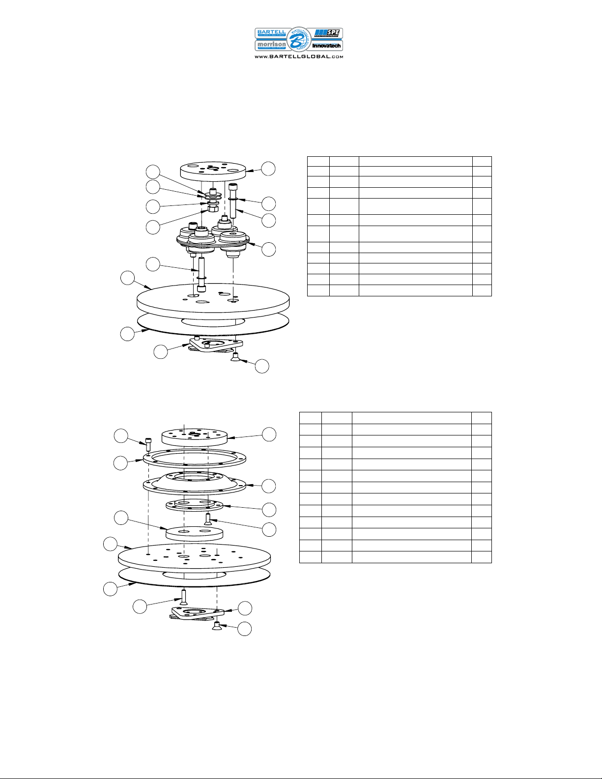
CUTTER HEAD UNITS
FLOATING HEAD ASSEMBLY (PART # 96-0027)
RIGID HEAD ASSEMBLY (PART # 96-0028)
NOTES:
1. INDICATED ITEM CONSISTS OF BUILD-UP OF 3 LAYERS OF
POLYCORD DISCS AS FOLLOWED: 1 PIECE OF PART # 13-0117
(.043" THICK) STACKED ON TOP OF 2 PIECES OF PART # 13-0118
(.073" THICK). INSTALLATION REF: DISCS TO BE INSTALLED
WITH THINNER DISC'S BLACK COATED SIDE ORIENTED TOWARD
ASSEMBLY'S TOP PLATE.
2. INDICATED SCREWS TO BE USED FOR ATTACHING ASSEMBLY
TO CUTTER HEAD SHAFT.
3. SECURE INDICATED SCREWS WITH A MEDIUM STRENGTH
THREAD LOCKING COMPOUND (E.G. LOCTITE 242).
ITEM PART # DESCRIPTION QTY
1 11-0036 Washer, 7/16" 2
2 11-0079 Hex head cap screw, 7/16"-14 x 1-1/4" 1
3 11-0147 S cket head cap screw, 3/8"-24 x 2" 4
4 11-0162 Washer (Belleville, serrated), 3/8"
(.413 ID x .630 OD) 4
5 11-0320 Washer (split-l ck), 7/16" 1
6 11-0348 Flat head s cket screw, 5/16-18 x 1/2 3
7 13-0056 Flexible c upling 1
8 13-0186 Velcr mat 1
9 51-0139 Cutter head fl ating head b tt m plate 1
10 51-0140 Cutter head fl ating head t p plate 1
11 96-0025 Cutter head triangle h lder assy 1
ITEM PART # DESCRIPTION QTY
1 11-0120 Flat head s cket screw, 1/4"-20 x 1" 2
2 11-0140 Flat head s cket screw, 1/4"-20 x 1" 8
3 11-0141 S cket head cap screw, 1/4"-20 x 5/8" 8
4 11-0348 Flat head s cket screw, 5/16-18 x 1/2 3
5 13-0116 Cutter head rigid head rubber spring disc 1
6 13-0118 Cutter head p lyc rd 1
7 13-0186 Velcr mat 1
8 51-0143 Cutter head rigid head t p plate 1
9 51-0144 Cutter head rigid head p lyc rd hub 1
10 51-0145 Cutter head rigid head p lyc rd ring 1
11 51-0146 Cutter head rigid head b tt m plate 1
12 96-0025 Cutter head triangle h lder assy 1
P32NDX – P32ND OWNER’S MANUAL
18
3
5
16
6
14
15
13
10
11
8
cable t p wer
c ntr l unit ( n
frame handle)
cable t
p wer
s urce
t m t r
see
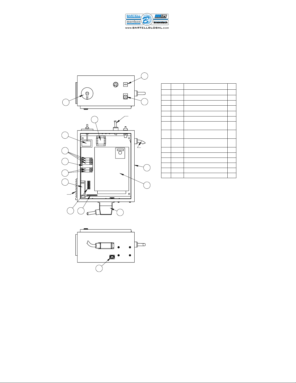
n te 3 N tes:
1. P wer n/ ff switch.
2. P wer pr visi n f r water mister pump.
3. Replacement filters f r vents: 81-0364.
12
9 see n te 2
2
7
4
see n te 2
see n te 1
INVERTER BOX - P32 "ND" SERIES
ITEM PART # DESCRIPTION QTY
2 22-0019 Switch (circuit bre ker rot ry h ndle) 1
3 22-0050 Cont ctor (32A, 3 pole, 24V coil) 1
4 22-0060 Switch (on/off) 1
5 23-0055 VFD (20HP, 480VAC, 3 ph se) 1
6 23-0056 Quick-disconnect wiring connector 1
7 23-0061 Hour meter 1
8 23-0077 Circuit bre ker b se (with link ge
mech nism 23-0076) 1
9 23-0145 Power Receptic l, IEC Appli nce
Outlet, Sn p-In 1
10 23-0146 Tr nsformer, 150VA du l volt ge
output 1
11 23-0147 Fuse (1A, 250 VAC, time del y) 3
12 23-0148 Fuse (1.5A, 600 VAC) 2
13 25-0151 F n 1
14 25-0153 Ground b r 1
15 25-0154 Termin l block 1
16 96-0307 Inverter enclosure ( ssembled shell) 1
P32NDX – P32ND OWNER’S MANUAL
19
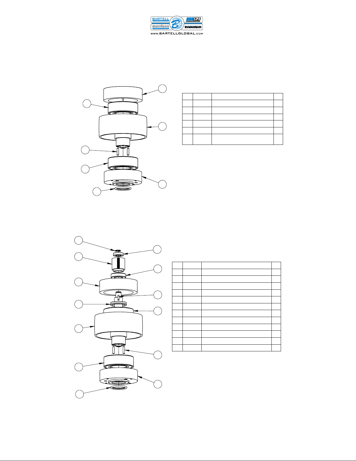
SEE
NOTE 1
4
3
2
1
1
5
6
NOTE:
1 O-RING RESIDES INSIDE BEARING HOUSING'S
GROOVED OPENING.
CUTTER HEAD PULLEY (WITHOUT TOP PULLEY) - P32 "ND" SERIES (#96-0282)
ITEM PART # DESCRIPTION QTY
1 13-0120 Bearing (60x110x36.5) 2
2 13-0131 O-ring (2" ID x 2-3/8" OD x 3/16" W) 1
3 13-0134 D wel pin, 1/4" dia. x 1" l ng 2
4 51-0002 Bearing h using (cutter head, t p) 1
5 51-0191-6 Cutter head pulley 1
6 51-0867 Bearing h using (cutter head,
b tt m) 1
5
6
7
12
3
8
1
11
2
4
9
10
1
SEE
NOTE 1
NOTE:
1. O-RING RESIDES INSIDE BEARING HOUSING'S
GROOVED OPENING.
CUTTER HEAD PULLEY (WITH TOP PULLEY) - P32 "ND" SERIES (#96-0281)
ITEM PART # DESCRIPTION QTY
1 13-0120 Bearing (60x110x36.5) 2
2 13-0131 O-ring (2" ID x 2-3/8" OD x 3/16" W) 1
3 13-0133 D wel pin, 3/16" dia. x 5/8" 1
4 13-0134 D wel pin, 1/4" dia. x 1" l ng 2
5 13-0144 Retaining ring (E-style)- f r 3/4" shaft 1
6 13-0208 Bearing (20 ID x 37 OD x 9 W) 1
7 13-0327 Bearing, 30 ID x 55 OD x 13 W 1
8 13-0330 V-ring seal (1.93 ID x 2.33 OD x .35 H) 1
9 51-0191-5 Cutter head pulley (with t p shaft) 1
10 51-0845 Gear pulley 1
11 51-0867 Bearing h using (cutter head, b tt m) 1
12 51-0868 Bearing h using (cutter head, t p) 1
This manual suits for next models
1
Table of contents
Other Innovatech Floor Machine manuals


Popular Floor Machine manuals by other brands


Grillo
Grillo FD 220L Operator's manual

Nilfisk-Advance
Nilfisk-Advance Advance ES300 ST Instructions for use

Sandia
Sandia 86-4000-H Operation and maintenance manual

Tornado
Tornado Pro-Glazer H13-24 Operation and maintenance manual

Husqvarna
Husqvarna PG820 RC Operator's manual

DiamaPro Systems
DiamaPro Systems DPBRN27-X+ owner's manual