DiamaPro Systems DPBRN27-X+ User manual

OWNER’S MANUAL
DPBRN27-X+
27” PROPANE BURNISHER
OPERATION & MAINTENANCE MANUAL
SAVE THESE INSTRUCTIONS FOR FUTURE REFERENCE

WARRANTY REGISTRATION CARD
Form must be completed and submitted within 30 days from the date of purchase.
Customer Information
First and Last Name
Company Name
Address City State Zip Code
Phone Number Email
Machine Information
Machine Type Machine Model
Serial # Purchase Date (dd/mm/yy)
DiamaPro®Systems
3343 Peachtree Road NE
Suite 145 #24
Atlanta, GA 30326
470-977-2323 nwww.diamaprosystems.com ninfo@diamaprosystems.com

Thank you for purchasing a DIAMAPRO®SYSTEMS product. This manual
provides information and procedures to safely operate and maintain the
DiamaPro®DPBRN27-X+. For your own safety and protection from injury,
carefully read, understand, and observe the safety instructions described
in this manual. Keep this manual or a copy of it with the machine. If you
lose this manual or need an additional copy, please contact DiamaPro®
Systems. This machine is designed and built with user safety in mind; how-
ever, it can present hazards if improperly operated and serviced.
Please follow the operating instructions carefully. If there are any questions
regarding operating or servicing of this machine, please contact
DiamaPro®Systems.
Disclaimer: DiamaPro® Systems and its aliates take no responsibility
for any damage, injury or death resulting from the incorrect or unsafe use
of this product. Use of this product should be undertaken by competent
persons only. It is the operator’s responsibility to ensure that the following
safety procedures are followed. If you are unsure, do not operate this
product.
WARNING!
Failure to read the Operator Manual prior to operating or
attempting any service or maintenance procedure to your ma-
chine could result in death or injury to you or others, or damage
to the machine or to other property. You must have training
in the operation of this machine before using it. If you or your
operator/operators cannot read English, have this manual
explained fully before attempting to operate this machine.
WARNING!
It is the owner/operator’s responsibility to ensure that the
air-exchange system installed in any location where a propane
oor care machine is being operated is of sucient capacity
and quality to support the use of such a machine. OSHA and
other County, State, or Federal Agencies publish guidelines on
this subject that are usually most readily found in the posses-
sion of the respective owners and/or parent companies of any
location or chain of locations. Failure on the part of the owner
operator to ensure that a propane oor care machine can be
operated safely in a given location may lead to injury, sickness
or even loss of life.
WARNING!
This product contains one or more chemicals known to the
State of California To cause cancer and birth defects or other
reproductive harm. Wash hands after handling.
The following terms and symbols are used to identify statements of poten-
tial hazards which aect safety of yourself and others. Read and observe
all safety statements found on this Operator Manual and on your engine.
DANGER:
The signal word DANGER indicates a hazardous situation
which, if not avoided according to the instruction found in this
Operator Manual or on your machine, will result in death or
serious bodily injury.
WARNING:
The signal word WARNING indicates a hazardous situation
which, if not avoided according to the instruction found in this
Operator Manual or on your machine, could result in death or
serious bodily injury.
CAUTION:
The signal word CAUTION indicates a hazardous situation
which, if not avoided according to the instruction found in this
Operator Manual or on your machine, could result in minor or
moderate injury or damage to your engine or property.
INTRODUCTION
1. SAFETY
1.1. Safety Precautions
1.3. Description of Safety Symbols
1.2. Safety Information
The following safety symbols are used on the product and in this manual
to alert the operator of potential safety hazards. Read them carefully, and
understand their meaning.
Indicates DANGER, WARNING, or CAUTION
Read Operator Manual before operating his machine. Failure to
follow directions could result in death or serious injury.
Engine exhaust contains carbon monoxide, an odorless and
deadly gas. Follow all Carbon Monoxide Safety instructions in
this Operator Manual, Propane Engine Supplemental Operator
Manual, and on machine. Failure to follow directions could
result in death or serious injury.
Propane is highly ammable. Follow all Propane Safety instruc-
tions in this Operator Manual, Propane Engine Supplemental
Operator Manual, and on machine. Failure to follow directions
could result in death or serious injury.
Wear eye and hearing protection when operating this machine.
Do NOT touch hot muer, exhaust pipe, or cylinder.
These parts are extremely hot from operation and
may remain hot after operation. Severe burn or injury
could occur if you touch these parts.
There are rotating pads and parts under machine
frame, which can cause serious injury. Keep hands
and feet away.
DANGER: Severe burn or injury could occur if you touch the hot
muer, exhaust pipe, or cylinder. Do NOT Touch these hot parts.
WARNING: Any alterations or modications of this engine could
result in damage to the engine or injury to the operator or other
bystanders. Alterations or modications not authorized by the man-
ufacturer voids any and all warranties and liabilities.
WARNING: To avoid injury or property damage, DO NOT leave
the machine where it can be tampered with or started by persons
untrained in its operation.
WARNING: Moving parts of this machine can cause serious injury
and/or damage. Do not allow contact of clothing, hair, hands,
feet, or other body parts with the rotating pad. Keep other people
away from the machine while it’s in operation. DO NOT leave the
machine or engine running unattended.
WARNING: Operate the machine at a slow or moderate pace. DO
NOT run when operating the machine.
WARNING: Injury to the eyes and/or body can occur if protective
clothing and/or equipment is not worn while using this engine.
Always wear safety goggles and safety clothing while using this
machine.
WARNING: Long or continuous exposure to high noise levels may
cause permanent hearing loss. Always wear hearing protection
while using this machine.
WARNING: Injury to the operator or bystanders could occur if the
machine’s power is on while changing the bung pad or making
machine adjustments. Never try to change the bung pad or at-
tempt to make machine adjustments while the engine is running.
WARNING: Keep bystanders away from the engine while it is in
operation.
1.4. General Operation Safety

WARNING: Substantial damage to the oor, the machine, or
personnel may result if the machine is operated with the pad o
center, damaged or missing. Do not operate the machine if the
pad is o center, damaged or missing.
WARNING: Operating an engine that has loose parts could result
in injury or property damage. DO NOT operate this engine if there
are loose parts. Inspect the engine for loose parts frequently. This
will promote safe operation and a long engine life.
WARNING: Vibration from machinery may cause numbness or
tingling of the ngers in certain people. Smoking, dampness, diet,
and heredity may contribute to the symptoms. Wearing warm
clothing, gloves, exercising and refraining from smoking can re-
duce the eects of vibration. If the symptoms still persist, discon-
tinue operation of the machine.
CAUTION: OVERHEATING is a major cause of engine failure.
Keep the engine clean and free of debris build up.
CAUTION: Low oil levels and dirty oil account for most of the other
failures. Follow the engine manual’s recommended oil change
schedule.
1. Check engine oil level according to Engine Operator Manual
2. Ensure propane cylinder has been properly lled according to section
“Filling Propane Cylinders”
3. Check for any sign of wear or damage such as cracks, corrosion, punc-
tures, etc. to the fuel system including propane cylinder, fuel hoses,
ttings, regulator, carburetor, and electrical components.
4. Ensure main service valve on propane cylinder is closed (turned
clockwise).
5. Screw the REGO tting of the high-pressure propane hose onto the
cylinder service valve and hand tighten. This connection MUST be tight
and secure and fully seated to function.
6. Ensure propane tank is secured with clamping strap
7. Ensure handle is secure and at a comfortable position
8. Ensure all machine parts (belt, pad, handle, wheels, etc.) are in place
and secure.
9. Ensure the pad is at least 1/3 inch thick, and that the pad holder is tight.
10. Ensure the pad driver is secure to the drive shaft.
11. Ensure the battery cable is connected.
WARNING: Before attempting to start engine, become familiar
with all controls of the machine.
1. Slowly open the main service valve on propane cylinder to the fully
open position.
2. Set throttle to Idle position.
3. Ensure machine is rocked back on its rear casters, so the pad is not in
contact with the oor.
4. Turn Ignition Switch to “Start”, which will engage starter. Allow cranking
for a maximum of 6 seconds or until the engine res.
If engine fails to re on the rst attempt, repeat this step. It will likely re
on the second attempt due to internal fuel priming.
CAUTION: Serious starter damage will result if starter is engaged
for more than 6 seconds, and will void warranty.
5. Once engine has started, slowly increase throttle. Allow for a warm-up
period for 30 Seconds before applying full load to the engine.
Note: If the engine fails to start, see the Troubleshooting Guide.
2. OPERATION
2.1. Preparation
2.2. Starting the Engine
3. STOPPING ENGINE
Normal Stop
Follow these stopping procedures under normal use, including when the
engine will be stored or transported:
1. Set throttle to Idle position.
2. Close the service valve on propane cylinder (turn clockwise fully).
3. Allow the remaining propane in the regulator and fuel hose to be
consumed by engine, until engine stops.
4. Turn engine key switch to o.
5. Disconnect fuel line from propane cylinder.
6. If storing or transporting the machine, follow instructions in section
“STORING & TRANSPORTING PROPANE CYLINDERS”
Immediate Stop
Follow these stopping procedures only when an immediate stop is
required:
1. Turn engine key switch to o.
2. Close the service valve on propane cylinder (turn clockwise fully).
3. Disconnect fuel line from propane cylinder.
The handle on this machine can be adjusted to several heights, to accom-
modate dierent sized operators and dierent operator preferences.
To adjust the handle:
1. Stop the engine.
2. Loosen the Handle Adjustment Knob, until the Handle is allowed to pivot
freely. Note: Do not fully remove this knob.
3. Adjust the Handle to desired position.
4. Tighten the Handle Adjustment Knob.
The position of the two front wheels has signicant aect on the perfor-
mance and handling of the machine, including:
Pad pressure = The amount of force the pad has against the oor
Forward propulsion = The feeling of forward pull or drive caused by pad
friction
Machine torque = The feeling that the machine wants to constantly turn,
usually toward the left
When your machine was assembled, the wheels were installed in posi-
tions determined to allow for best performance under most conditions.
However, depending on oor type, oor nish type, pad type, and
operator preference, these wheel positions can be changed to aect
machine performance.
For the purpose of clarity, the following terms will be used in this section:
Forward = closer to the front of the machine
Rearward = closer to the rear of the machine
Up = closer to the sky
Down = closer to the ground
Left = the left side when viewed from the Operator’s position
Right = the right side when viewed from the Operator’s position
Through wheel adjustment, the following changes can be made to the
machine performance:
To change the wheel position:
1. Stop the engine.
2. Adjust handle position to highest position and rock machine back, until
handle grips are resting on ground.
3.1. Handle Adjustment
4. WHEEL POSITION ADJUSTMENT
DESIRED CHANGE
Increase pad pressure
Decrease pad pressure
Increase forward propulsion
Decrease forward propulsion
Increase machine torque
Decrease machine torque
ADJUSTMENT TO MAKE
Move both wheels (left and right) Rearward
Move both wheels (left and right) Forward
Oset the two wheels, so the right wheel is
Higher (more “up”) than left
Align the two wheels, so the left and right
wheel are the same height
Move both wheels (left and right) Down
Move both wheels (left and right) Up

CAUTION: Whenever working on a machine in the rocked back
position, ask an assistant to hold the handle and prevent the ma-
chine from falling forward.
3. Remove the small cotter pin / hair pin from the wheel axle.
4. Remove the wheel axle.
5. Remove the wheel and any spacer.
6. Reposition the wheel and spacer in desired hole.
7. Insert the wheel axle.
8. Insert the cotter pin / hair pin.
WARNING: To ensure personal safety, adjustments should ONLY
be made by a qualied technician or an authorized service enter.
WARNING: Prior to any maintenance, ensure engine is turned o
and disconnect spark plug wire from spark plug. Never attempt
service or maintenance on a running engine.
The equipment uses an onboard charging system integrated within the
wiring harness which charges battery during normal use.
The battery can be recharged oine with any o-the-shelf battery charger
with the following specs:
Voltage = 12 volts
Charging Amperage = 0.5 to 15 Amps
Battery Charging Procedures:
1. Disconnect the plastic battery cable terminal on equipment, and remove
battery from equipment.
2. Connect the charger clamps to the battery posts:
• Red clamp on the positive “+” post
• Black clamp on the negative “-” (ground) post
3. If the charger has settings, set the output voltage and amperage within
the ranges noted above.
4. Plug in the battery charger to standard wall outlet in a well ventilated
area.
5. For best results, leave the charger connected for minimum of 8 hours.
6. Disconnect battery from charger by reversing steps 5-2
7. Reinstall battery on equipment, and connect the plastic battery cable
terminal.
5. MAINTENANCE
5.1. Maintenance Schedule
Check Engine Oil Level
Check for Loose Hardware
Check for Fuel or Oil Leakage
Check/Clean Intake Air Filter
Check/Clean Bonnet Filter
Check, Clean, and/or Replace Dust Bag
Check Pad
Check Shroud & Shroud Seal
Check Engine Mounts
Check Belt for Wear or Slippage
Check Pulleys, Drive Shaft, and Bearings
Check Wheels & Bearings
Overall Checkup at Authorized Service Center
DAILY
X
X
X
X
X
X
X
X
25HR
X
X
X
X
200HR
X
5.2. Battery Maintenance
Battery Specs:
Model
Voltage (V)
Capacity (Ah)
Weight
Charging Current
Charging Voltage
Cold Cranking Amps
Cycle Life
HJTZ5S-30-GFP
12.8
3
0.7 kg / 1.5 lb
0.5A to 15A
14.4 0.5 V
180
≥1000
5.3. Dust Collection Maintenance
If equipped with a dust collection system, the dust bag should be serviced
frequently as follows:
1. Stop engine.
2. Remove the bag from the dust chute, but pulling the elbow out of the
dust chute.
3. Unzip the back of the bag.
4. Empty the contents of the bag into a garbage receptacle and shake out
any debris. This is best done outside.
5. Reinstall the bag onto the dust chute, and secure the bag to machine
via the rope loop and Velcro on bag.
Note: The bag will remain functional for approximately 20-30 cycles, after
which the bag should be replaced.
1. Stop the engine.
2. Adjust handle position to highest position and rock machine back, until
handle grips are resting on ground.
WARNING: Whenever working on a machine in the rocked back
position, ask an assistant to hold the handle and prevent the ma-
chine from falling forward.
3. Remove the Pad Holder by turning it counterclockwise.
4. Remove the Pad, by pealing it o of the gripper surface
5. Install a new Pad onto the gripper surface, paying attention to keep it
centered and aligned with the gripper surface.
6. Reinstall the Pad Holder, and tighten it by turning it clockwise.
Take the following steps when storing the machine:
1. Ensure the ignition switch is turned to “o”.
2. Remove the propane tank, and store in an approved outside location.
3. Disconnect battery cable connectors, to prevent battery drain. When
disconnected, the battery will keep its charge in storage for
approximately 12 months.
4. Store machine in an indoor, climate controlled location with low
humidity.
6. HOW TO CHANGE PAD
7. STORAGE

8. TROUBLESHOOTING
Note: When troubleshooting, always rst check for simple causes which may at rst seem too obvious. For example, an engine unable to start may be
caused by an empty propane cylinder or an unopened service valve.
SYMPTOM POSSIBLE CAUSE CORRECTIVE ACTION
Engine does not turn over.
Weak or dead battery. Recharge or replace battery.
Battery cable is disconnected. Connect battery cable at connector.
Ignition switch faulty. Check switch, replace if necessary.
Faulty Starter. Check starter, replace if necessary.
Damaged or disconnected wire in
wiring harness.
Check wiring harness to identify faulty con-
nection, replace or reconnect as required.
Numerous other causes. See engine manual or dealer.
Engine turns over, but does
not start or run.
Propane cylinder is empty. Rell cylinder or replace with full cylinder.
Main fuel service valve on propane
cylinder is closed.
Manually open main fuel service valve on
propane cylinder.
REGO tting (fuel hose to cylinder
connector) is not fully seated.
Manually close main fuel service valve. Dis-
connect REGO tting. Reconnect and hand
tighten to ensure secure connector is fully
seated. Slowly open main fuel service valve.
Propane cylinder OPD (overow pro-
tection device) has been triggered
Manually close main fuel service valve. Dis-
connect REGO tting. Wait 5 seconds. Re-
connect and hand tighten to ensure secure
connector is fully seated.
Slowly open main fuel service valve.
Propane regulator out of adjustment or
faulty.
Have certied dealer inspect regulator and
adjust or replace.
Poor quality propane causes deposits
of particles in regulator or valves.
Have certied dealer inspect regulator and
clean or replace. Service engine valves
according to engine manual instructions.
Contact propane supplier to provide clean
HD5 propane.
Spark plug not ring. Replace spark plug.
Faulty oil pressure switch. Check or replace oil pressure switch.
Numerous other causes. See engine manual or dealer.
Propane regulator freezes
and prevents ow of
propane.
Liquid propane is entering
regulator.
• Ensure cylinder is designed for VAPOR
withdrawal.
• Ensure cylinder is designed for the correct
orientation (horizontal or vertical).
• Ensure cylinder is installed in correct ori-
entation. Make sure locator pin is inserted
into positioning slot on cylinder collar, and
follow orientation arrow indications/labels on
cylinder.
• Ensure propane cylinder is not overlled.
• Ensure use of application does not allow
operating angles to exceed equipment OEM
instructions.
Low ambient temperature.
It is normal condition for propane regulator
to operate at colder temperature than ambi-
ent, which may cause condensation or frost
formation depending on ambient
temperature and humidity levels.

SYMPTOM POSSIBLE CAUSE CORRECTIVE ACTION
Propane cylinder
forms condensation
or ice.
Propane fuel is leaking.
Close propane main fuel service valve.
Check fuel lines, REGO tting, and regulator
for any leaks.
Propane consumption is abnormally
high.
Refer to section “Inconsistent or short
cylinder run time” below.
Low ambient temperature.
It is normal condition for propane cylinder to
operate at colder temperature than ambient,
which may cause condensation or ice forma-
tion depending on ambient temperature and
humidity levels.
Inconsistent or short
cylinder run time.
Propane cylinders not lled consistently. Use cylinders that are properly and
consistently lled to the 80% maximum level.
Propane regulator out of adjustment or
faulty.
Have certied dealer inspect regulator and
adjust.
Dirty air lter. Service air lter.
Excessive engine load. See engine manual or dealer.
Excessive engine RPM. See engine manual or dealer.
Engine backres, dicult
to start, reduced power,
over-heating, or other
poor performance
Propane regulator out of adjustment
or faulty.
Have certied dealer inspect regulator and
adjust.
Propane ow restricted. Refer to section “Engine turns over, but does
not start or run”, above.
Dirty air lter. Service air lter.
Dirty propane lter. Service propane lter.
Ignition system faulty. Check or replace ignition coils.
Poor compression. See engine manual or dealer.
Engine timing issue. See engine manual or dealer.
Cooling ns clogged. See engine manual or dealer.
Numerous causes. See engine manual or dealer.
Excessive machine
vibration.
Pad is not centered on pad driver. Remove pad and reinstall, paying attention to
center it on pad driver.
Pad driver is damaged. Inspect pad driver and replace if necessary.
Front end bearings are
worn/damaged.
Inspect front end bearings and replace if
necessary.
Clutch failure.
Blown fuse. Check fuses in Electronic Box and replace if
necessary.
Disconnected wire at clutch. Check wires that connect the actual clutch to
the wiring harness. Reconnect if necessary.
Disconnected wire under ignition
switch.
Check wires that connect clutch handles to
wiring harness located under the ignition
switch. Reconnect if necessary.
Engine monitor shuts down
machine.
Engine is running rich. Have certied dealer inspect regulator and
adjust.
Engine monitor is faulty Replace engine monitor.
Battery does not hold a charge. Battery is faulty. Replace battery.
Battery is not being charged
during machine running.
Faulty voltage regulator. Replace voltage regulator.
Damaged or disconnected
wire in wiring harness.
Check wiring harness to identify faulty con-
nection, replace or reconnect as required.
8. TROUBLESHOOTING (cont.)

This machine is powered by an engine that uses propane fuel.
Additional information about propane basics, propane cylinders, lling
propane cylinders, and storing and transporting propane cylinders is
provided in the “Propane” section of this operator manual. The following
propane safety instructions should be fully understood and followed at
all times when using this machine or propane cylinders. Failure to follow
directions could result in death or serious injury.
DANGER: Propane is a highly ammable fuel. Cigarette lighters,
pilot lights, and any other sources of ignition can create an explo-
sion when in contact with propane. All sources of ignition should
be extinguished or removed entirely from the work area. DO NOT
SMOKE in the vicinity of a propane powered engine, machine, or
propane cylinder.
DANGER: NEVER release or bleed propane inside any building or
other enclosed space or near an open pit. Check for fuel leaks and
damage to the propane cylinder prior to operating machine and
storage. Turn o service valve on propane cylinder when machine
is not in use. Always store propane cylinder in an approved
outside location. It is UNLAWFUL to store a propane cylinder
inside a building.
WARNING: If you smell propane gas, shut o the machine and
turn o service valve on propane cylinder and move machine out-
side. Determine the source of the leak before using it again.
WARNING: Escaping propane can freeze skin and cause frostbite
and damage eyesight. Always wear safety gloves and safety
glasses when lling propane cylinders.
INTRODUCTION:
This Operator’s Manual provides important information about safety, oper-
ation, transportation, storage maintenance, and warranty of your propane
engine and propane cylinders.
SAFETY HAZARD INTENSITY LEVEL:
The following terms and symbols are used to identify statements of poten-
tial hazards which aect safety of yourself and others. Read and observe
all safety statements found on this Operator Manual and on your engine.
DANGER: The signal word DANGER indicates a hazardous situa-
tion which, if not avoided according to the instruction found in this
Operator Manual or on your engine, will result in death or serious
bodily injury.
WARNING: The signal word WARNING indicates a hazardous
situation which, if not avoided according to the instruction found
in this Operator Manual or on your engine, could result in death or
serious bodily injury.
CAUTION: The signal word CAUTION indicates a hazardous
situation which, if not avoided according to the instruction found
in this Operator Manual or on your engine, could result in minor or
moderate injury or damage to your engine or property.
IMPORTANT SAFETY INSTRUCTIONS:
DANGER:
• Propane is a highly ammable fuel. Cigarette lighters, pilot lights, and
any other sources of ignition can create an explosion when in contact
with propane. All sources of ignition should be extinguished or removed
entirely from the work area. DO NOT SMOKE in the vicinity of a propane
powered engine or propane cylinder. If you smell propane gas, shut
o the engine. Determine the source of the leak before using it again.
NEVER vent propane gas inside a building. It is UNLAWFUL to store a
propane cylinder inside a building.
• Severe burn or injury could occur if you touch the hot muer or exhaust
pipe. DO NOT TOUCH THE HOT MUFFLER OR EXHAUST PIPE.
9. PROPANE SAFETY
PROPANE SUPPLEMENTAL
OPERATOR MANUAL
• The combustion of propane by this engine produces carbon monoxide,
a deadly, colorless, odorless, poisonous gas. This engine is specically
calibrated to operate at a very “lean” air/fuel ratio which minimizes the
production of carbon monoxide. Additionally, a catalyst muer is provided
with this engine which specically targets and eliminates any remaining
carbon monoxide, making it safe to operate indoors.
• DO NOT OPERATE THIS ENGINE WITHOUT THE CATALYST
MUFFLER.
• DO NOT TAMPER WITH REGULATOR OR OTHER SETTINGS WHICH
WOULD ALTER AIR/FUEL RATIO.
• INSURE ANY INDOOR SITE OF USE HAS ADEQUATE VENTILATION
WHICH MEETS INDUSTRY STANDARDS
WARNING:
• Propane is a highly ammable fuel. Cigarette lighters, pilot lights, and
any other sources of ignition can
• Failure to read the Operator Manual prior to operating or attempting any
service or maintenance procedure to your engine could result in injury to
you or others, or damage to the engine or to other property.
You must have training in the operation of this engine before using it. If
you or your operator/operators cannot read English, have this manual
explained fully before attempting to operate this engine.
• Any alterations or modications of this engine could result in damage
to the engine or injury to the operator or other bystanders. Alterations
or modications not authorized by the manufacturer voids any and all
warranties and liabilities.
• To avoid injury or property damage, DO NOT leave the engine where it
can be tampered with or started by persons untrained in its operation.
• DO NOT leave the engine running unattended.
• Operating an engine that has loose parts could result in injury or property
damage. DO NOT operate this engine if there are loose parts. Inspect
the engine for loose parts frequently. This will promote safe operation
and a long engine life.
• Keep bystanders away from the engine while it is in operation.
• Injury to the eyes and/or body can occur if protective clothing and/or
equipment is not worn while using this engine. Always wear safety gog-
gles and safety clothing while using this engine.
• Long or continuous exposure to high noise levels may cause permanent
hearing loss. Always wear hearing protection while using this engine.
• Injury to the operator or bystanders could occur if the engine is running.
Never attempt to make engine adjustments while the engine is running.
• Dangerous carbon monoxide emissions from this engine will increase
greatly due to a dirty air cleaner.
Follow the engine manufacturer’s air cleaner service instructions.
CAUTION:
• Overlling propane cylinders is the number one cause of damage to
the propane fuel system. This fuel system is designed to run o vapor
propane, not liquid propane. When the cylinder is overlled, liquid pro-
pane will enter the fuel system and can damage lock-o and regulator, in
addition to causing the engine to run poorly or not at all. This voids the
warranty on aected parts of the engine. To avoid problems, read and
understand fully, the section “FILLING PROPANE CYLINDERS”.
• OVERHEATING is a major cause of engine failure. Keep the engine
clean and free of debris build up.
• Low oil levels and dirty oil account for most of the other failures. Follow
the engine manual’s recommended oil change schedule.
• Propane is ammable and commonly used as a fuel.
• The molecular formula of propane is C3H8, and it is in the family of lique-
ed petroleum gases (LP gases).
The other LP gases include butane, propylene, butadiene, butylene, isobu-
tylene and mixtures thereof.
• Propane is commonly available and has proven to be a dependable,
safe, economical, and clean burning fuel.
It can be used as a household fuel, industrial fuel, and fuel for internal
combustion engines. Propane has been used as a fuel since 1910.
• At atmospheric pressure, propane boils at -44 degrees Fahrenheit,
meaning it typically exists as a vapor.
However, when contained under pressure, such as in a propane cylinder,
it can exist as a liquid.
• Propane is naturally odorless, but includes an additive odorant, usually
mercaptan, which gives it a distinct odor similar to rotten eggs or skunk.
• Vapor propane is heavier than air, meaning it will settle in low areas such
as along the ground or in drains.
10. ABOUT PROPANE

PROPANE CYLINDERS (TANKS):
WARNING: NEVER use a cylinder not intended engine fuel
applications. DO NOT substitute cylinders that are used with
a barbecue grill, etc.
Propane cylinders are constructed according to ASME and Federal DOT
#4ET20 pressure safety codes. All valves and ttings are UL Listed.
Propane gas is noncorrosive and will not rust the inside of a cylinder. It is
recommended to have propane cylinders inspected regularly during re-ll
by an authorized National LP Gas Association propane dealer. The fuel
cylinder is supplied directly from the manufacturer and is void of propane.
PROPANE CYLINDER CONFIGURATIONS:
Propane cylinders are constructed to function in specic congurations.
The primary conguration options are:
• Propane Withdrawal: Vapor or Liquid
• Cylinder Orientation: Horizontal or Vertical
IMPORTANT: Dierent cylinder congurations are not interchangeable.
All DiamaPro®Systems engines use Vapor cylinders, and the orientation
can be either Horizontal or Vertical.
CAUTION: Do not use propane cylinders that are liquid withdrawal
cylinders, such as cylinders for fork lift trucks or other liquid
withdrawal applications.
CAUTION: Always install the propane cylinder in the proper
orientation, which is identied by a label that say “THIS SIDE UP”
or equivalent.
CAUTION: Failure to use a proper cylinder or failure to install cyl-
inder in proper orientation will result in liquid propane withdrawal
and cause damage the regulator.
WARNING:
• Propane cylinders should only be lled by your propane provider or by
individuals who have been properly trained and certied.
• Escaping propane can freeze skin and cause frostbite and damage eye-
sight. Always wear safety gloves and safety glasses when lling propane
cylinders.
• DO NOT overll cylinders.
• DO NOT tamper with cylinder gauges or safety relief valves.
• At time of ll, ensure tank is in operable condition and meets all certi-
cation requirements. Discontinue use of any cylinder that is damaged or
rusted or does not comply with certication requirements. Your propane
service company will assist with compliance.
The maximum ll volume of a propane cylinder is ALWAYS considered
80% of the total cylinder volume to allow for expansion and to ensure
proper vapor withdrawal from the cylinder.
For example, if your propane cylinder is referred to as a “20 lb cylinder”,
this means that when the propane cylinder is 80% full, the weight of the
propane is 20 lb.
Cylinders should be lled in the vertical position.
When lling a propane cylinder, the xed liquid level gauge should be
opened (unscrewed counterclockwise) so it can be used to determine
when propane has reached 80% full. As propane is added during lling,
vapor will escape the small hole in this gauge. When the cylinder reaches
80% full, the escaping propane will turn to liquid propane. When this hap-
pens, the lling should be immediately stopped and the gauge should be
closed (turned clockwise).
CAUTION: Always use HD-5 grade propane to operate this
engine.
CAUTION: Propane cylinders must be purged at the time of the
rst ll. Your propane suppliers should be familiar with this
operation and will provide this service.
10.1. Filling Propane Cylinders
SYMPTOMS OF A NON-PURGED CYLINDER:
• Relief valve opens due to over pressurized cylinder creating hazardous
situation.
• Moisture in the cylinder.
• Powered engine operates initially but shuts down when propane mixture
becomes too lean
STORING & TRANSPORTING PROPANE CYLINDERS:
The NFPA Technical Committee prohibits the storage of propane cylinders
in buildings. Propane cylinders should NOT be stored in buildings used by
the public or frequented by anyone passing through or who is working in
the building. Full or empty, never leave cylinders in small enclosed areas.
Cylinders must be stored in a secure, tamper-proof storage enclosure that
provides safety from accident or vandalism.
Propane cylinders should always be transported either secured to the
machine using cylinder straps, or secured in an upright position during
transportation.
The engine performance, reliability and life are inuenced by many factors,
some external and some strictly associated with the quality of the products
used and with the scheduled maintenance. The following information allow
a better understanding and use of your engine.
ENVIRONMENTAL CONDITIONS:
The operation of a four-stroke endothermic engine is aected by:
a) Temperature:
– Working in low temperatures could lead to a dicult cold starting.
– Working in very high temperatures could lead to a dicult hot starting
due to the evaporation of the fuel either in the carburetor oat chamber
or in the pump.
– In any case, the right kind of oil must be used, according to the operating
temperatures.
b) Altitude:
– The higher the altitude (above sea level), the lower the max power
developed by an endothermic engine.
– When there is a considerable increase in altitude, the load on the ma-
chine should be reduced and particularly heavy work avoided.
OIL:
Use always high quality oils, choosing their viscosity grade according to
the operating temperature.
a) Use only detergent oil classied SJ,SL or higher are acceptable.
b) Choose the SAE viscosity grade of oil from this chart:
– from 5 to 35 °C = SAE 30
– from -25 to + 5 °C = 5W-20 or 5W-30 (Multi-viscosity)
– from -7 to + 35 °C = Synthetic oils 10W-30 or 15W-40 (Multi-viscosity)
c) The use of multi-viscosity oils in hot temperatures will result in higher
than normal oil consumption; therefore, check oil level more frequently.
d) Do not mix oils of dierent brands and features.
e) SAE 30 oil, if used below 5°C, could result in possible engine damage
due to inadequate lubrication.
f) Oil should be at “MAX” mark do not overll. Overlling with oil may
cause:
– Smoking;
– Spark plug or air lter fouling, which will cause hard starting.
AIR FILTER:
A good quality fuel is the major issue for the engine reliability of operation.
The air lter must always be in perfect working order, to prevent debris
and dust from getting sucked into the engine, reducing the eciency and
life of the machine.
a) Always keep the ltering element free of debris and in perfect working
order.
b) If necessary, replace the ltering element with an original spare part.
Incompatible ltering elements can impair the eciency and life of the
engine.
c) Never start the engine without mounting the ltering element properly.
SPARK PLUG:
Not all the spark plugs for endothermic engines are the same!
a) Use only spark plugs of the recommended type, with the right heat
range.
b) Check the length of the thread, because – if too long – it will damage
the engine beyond repair.
c) Make sure that the electrodes are clean and their gap is correct.
11. NEED TO KNOW

12. STANDARDS OF USE
BEFORE EVERY USE:
Before every use, perform the following checking procedures in order to assure regular operation.
CHECK THE OIL LEVEL:
See the specic chapter for the oil to be used.
a) Place the engine level.
b) Clean around oil ll.
c) Unscrew the cap, clean the end of the dipstick and insert it, as illustrated, without screwing it down.
d) Remove the cap with the dipstick and check the oil level that must be between “MIN” and “MAX” marks.
e) If oil is required, add oil of the same kind up to the “MAX” mark, being careful not to spill any outside the oil ll.
f) Fully tighten the ller cap and wipe o any spilled oil.
CHECK THE AIR CLEANER:
The eciency of the air lter is fundamental for the engine to work properly. Do not start the engine if the ltering element is missing or broken.
a) Clean around the lter cover.
b) Open the clips of the two sides of the air lter cover.
c) Check the condition of the ltering element. It must be intact, clean and in perfect working order; if not, either carry out maintenance or replace it.
d) Put the cover back.
LONG STORAGE (OVER 30 DAYS):
In case the engine has to be stored for a long time (for example at the end of the season), a few precautions are needed to help the future start-up.
a) To prevent the formation of deposits inside the tank, empty it of fuel by unscrewing the carburettor oat chamber plug and collecting all the fuel in a
suitable container. At the end of the operation remember to screw the plug back on and fully tighten it.
b) Remove the spark plug and pour about 3 cl of clean engine oil into the spark plug hole, then, having blocked the hole with a rag, run the starter motor
briey to turn the engine for a few revs and distribute the oil over the inner surface of the cylinder. Finally replace the spark plug without connecting
the cable cap.
These troubleshooting steps are specic for propane fuel system issues. For other engine issues, refer to the Engine Operator Manual and/or OEM Equipment Manual.
13. TROUBLESHOOTING
PROBLEM REASON SOLUTION
Engine does not turn over
Weak or dead battery. Recharge or replace battery.
Ignition switch faulty. Check or replace switch.
Faulty safety interlock switch (operator
presence control).
Engage safety interlock switch (operator
presence control) prior to engaging starter.
Safety interlock switch (operator
presence control) not engaged.
Check or replace safety interlock switch
(operator presence control).
Numerous other causes. See engine manual or dealer.
Engine turns over, but
does not start or run
Propane cylinder is empty Rell cylinder or replace with full cylinder.
Main fuel service valve on propane
cylinder is closed
Manually open main fuel service valve on
propane cylinder.
REGO tting (fuel hose to cylinder
connector) is not fully seated
Manually close main fuel service valve. Dis-
connect REGO tting. Reconnect and hand
tighten to ensure secure connector is fully
seated. Slowly open main fuel service valve.
Propane cylinder OPD (overow pro-
tection device) has been triggered.
Manually close main fuel service valve.
Disconnect REGO tting. Wait 5 seconds.
Reconnect and hand tighten to ensure
secure connector is fully seated. Slowly open
main fuel service valve.
Propane regulator out of adjustment or
faulty
Have certied dealer inspect regulator and
adjust or replace.
Poor quality propane causes deposits
of particles in regulator or valves
Have certied dealer inspect regulator
and clean or replace. Service engine valves
according to engine manual instructions.
Contact propane supplier to provide clean
HD5 propane.
Spark plug not ring Replace spark plug.
Faulty vacuum switch Check or replace vacuum switch.
Faulty oil pressure switch Check or replace oil pressure switch.
Numerous other causes See engine manual or dealer.

13. TROUBLESHOOTING (cont.)
PROBLEM REASON SOLUTION
Engine backres, dicult
to start, reduced power,
over-heating, or other
poor performance
Propane regulator out of adjustment or
faulty
Have certied dealer inspect regulator and
adjust.
Propane ow restricted Refer to section “Engine turns over, but does
not start or run”, above.
Dirty air lter Service air lter.
Ignition system faulty Check or replace ignition coils.
Poor compression See engine manual or dealer.
Engine timing issue See engine manual or dealer.
Cooling Fins Clogged See engine manual or dealer.
Numerous causes See engine manual or dealer.
14. EMISSION CONTROL WARRANTY STATEMENT
EPA & CALIFORNIA EMISSION CONTROL WARRANTY STATEMENT
YOUR WARRANTY RIGHTS AND OBLIGATIONS
Federal law and California State law prohibits the following acts or the causing thereof: (1) the removal or The California Air Resources Board (CARB),
the U.S. Environmental Protection Agency (EPA), and LEHR, LLC (herein “LEHR”) are pleased to explain the emissions control system warranty on your
2015 small o-road engine (SORE). In California, new SORE must be designed, built and equipped to meet the State’s stringent anti-smog standards.
LEHR must warrant the emission control system on your SORE for the period of time listed below provided there has been no abuse, neglect or improp-
er maintenance of your SORE.
Your emission control system may include parts such as the carburetor, fuel-injection system, the ignition system, catalytic converter, fuel tanks, fuel
lines, fuel caps, valves, canisters, lters, vapor hoses, clamps, connectors, and other associated emission-related components. Where a warrantable
condition exists, LEHR will repair your SORE at no cost to you including diagnosis, parts and labor.
MANUFACTURER’S WARRANTY COVERAGE
The emission control system is warranted for 1000 hours (JLHRS.9992EM family) and 500 hours (JLHRS.6032EM family). If any emission-related part
on your equipment is defective, the part will be repaired or replaced by LEHR.
OWNER’S WARRANTY RESPONSIBILITIES
As the small o-road engine (SORE) owner, you are responsible for the performance of the required maintenance listed in your owner’s manual. LEHR
recommends that you retain all receipts covering maintenance of your SORE engine, but LEHR cannot deny warranty solely for the lack of receipts or for
your failure to ensure the performance of all scheduled maintenance.
As the SORE owner you should however be aware that LEHR may deny your warranty if your SORE or its part has failed due to abuse, neglect, im-
proper maintenance or unapproved modication. You are responsible for presenting your utility equipment engine to a LEHR distribution center as soon
as the problem exists. The warranty repairs should be completed within a reasonable amount of time, not to exceed 30 days. If you have any questions
regarding your warranty rights and responsibilities, you should contact LEHR.
GENERAL EMISSIONS WARRANTY COVERAGE
LEHR warrants to the ultimate purchaser and each subsequent purchaser that the equipment is:
Designed, built and equipped so as to conform with all applicable regulations; and
Free from defects in materials and workmanship that cause the failure of a warranted part to be identical in all material respects to that part as described
in the application for certication.
The warranty period begins on the date the equipment is delivered to an ultimate purchaser or rst placed into service. The warranty period is 1000
hours (FNYXS.9992EM family) and 500 hours (FNYXS.6032EM family).
Subject to certain conditions and exclusions as stated below, the warranty on emission-related parts is as follows:

14. MAINTENANCE
WARNING: Remove the spark plug cap and read instructions before carrying out any cleaning, repair, or maintenance operation. Wear proper
clothing and working gloves whenever your hands are at risk. Do not perform maintenance or repair operation without the necessary tools and
technical knowledge.
IMPORTANT: Never get rid of used oil, fuel or other pollutants in unauthorized places.
MAINTENANCE SCHEDULE:
Follow the hourly or calendar - whichever occurs rst - maintenance schedule shown in the following table.
OPERATION
AFTER
FIRST 5
HOURS
EVERY 5
HOURS
OR
DAILY
EVERY 50
HOURS
OR
EVERY
SEASON
EVERY
100
HOURS
EVERY
200
HOURS
EVERY
500
HOURS
Check oil level
Check or clean air inlet screen2
Change oil1
Clean silencer and engine
Air lter clearing2and check
Change oil lter
Check spark plug
Replace spark plug
Fuel lter check3
Replace air cleaner primary
element2
Replace air cleaner
secondary element2
1 ) Change oil every 25 hours if the engine is operating under heavy load or in hot weather.
2 ) Clean air lter more frequently if the machine is operating in dusty areas.
3 ) To be carried out by a specialized center.

CHANGE OIL:
See specic chapter for the oil to be used.
WARNING: Drain oil while the engine is warm, being careful not to touch the hot engine nor the drained oil.
a) Place the machine on a at surface.
b) Clean the area around the ller cap and unscrew the cap with dipstick.
c) Provide a suitable container for collecting the oil and unscrew the drain plug.
d) Ret the drain plug and fully tighten it having made sure that the gasket is in the right position.
e) Fill up with fresh oil.
f) Check that the oil level has reached the “MAX” notch on the dipstick.
g) Close the cap again and clean up any traces of oil that was possibly spilled.
NOTE: The oil capacity is about 2.0 Liter
WARNING: The length of time that propane can be left in your fuel tank and carburetor without causing functional problems will vary with such
factors as propane blend, your storage temperatures, and whether the fuel tank is partially or completely lled. The air in a partially lled fuel
tank promotes fuel deterioration. Very warm storage temperatures accelerate fuel deterioration. Propane will oxidize and deteriorate in storage.
Deteriorated propane will cause hard starting, and it leaves gum deposits that clog the fuel system. As a result, if the engine is not used for more
than one month, the fuel oil shall be drained thoroughly to prevent from deterioration of the fuel in the fuel system and carburetor. The failure of
the fuel system or engine performance arising from improper storage are beyond the scope of the warranty.
CLEAN SILENCER AND ENGINE:
Silencer must be cleaned when the engine is cold.
a) Use a jet of compressed air to remove any debris and dirt that could cause a re from the silencer and its protective cover.
b) Make sure that the cooling air intakes are not blocked.
c) Clean the plastic components with a sponge soaked in water and detergent.
AIR FILTER MAINTENANCE:
a) Clean debris in the air lter cap and rain cover.
b) Open the clips on the two sides of air lter cover.
c) Gently shake element up and down, take out air cleaner primary element and secondary element.
d) Tap the cartridge on a solid surface and blow it from the inside with compressed air to remove dust and debris.
IMPORTANT: Do not use water, petrol, detergents or any other products to clean the cartridge.
e) Clean the inside of the lter housing, making sure to block the inlet duct with a rag to prevent dust and debris from entering the engine.
f) Remove the rag blocking the air inlet duct. Reinstall the primary and secondary air lter elements.
g) Reinstall the air lter cover and secure it to the lter housing with the holding clips.
SPARK PLUG SERVICE:
a) Remove the spark plug using a spark plug socket wrench.
b) Clean the electrodes with a metal brush and remove any carbonaceous build-up.
c) Using a thickness gauge, check for the right gap (0.6-0.8mm) between the electrodes.
d) Install the spark plug and tighten with a socket wrench.
Replace the spark plug if the electrodes are burnt or if the porcelain is broken or damaged.
WARNING: Fire hazard! Do not check the ignition system with spark plug removed.
IMPORTANT: Use only spark plugs of the recommended type.
TUNING THE THROTTLE CABLE AND THE CARBURETOR:
Should the engine not reach maximum revs with the throttle trigger set to “FAST”, it could be due to the throttle trigger and speed control lever being out
of phase or to a carburetor problem. Go to a specialized center or contact your dealer to restore normal operation.
14. MAINTENANCE (cont.)

PROBLEM REASON SOLUTION
Hard starting
No fuel Check and top up
Stale fuel or build-ups in tank Empty fuel tank and rell with fresh
fuel
Incorrect starting procedure Perform the starting procedure cor-
rectly
Spark plug disconnected Check that the spark plug cap ts
well over the plug terminals
The spark plug is wet or the spark plug
electrodes are dirty or placed
inadequately
Check
Air lter clogged Check and clean
Incorrect oil for the season Replace with proper oil
Fuel evaporation in the carburetor
(vapor lock) due to high temperatures
Wait for a few minutes then start
again
Fault in carburation Contact a Licensed Service Center
Hard starting Contact a Licensed Service Center
Inconsistent working
Dirty electrodes or incorrect gap Check
The spark plug cap is inserted
incorrectly Check that the cap is tted correctly
Air lter clogged Check and clean
Throttle trigger in “CHOKE” position Move the lever to the “FAST” position
Fault in carburation Contact a Licensed Service Center
Fault in ignition Contact a Licensed Service Center
Air lter clogged Check and clean
Loss of power whilst operating
Fault in carburation Contact a Licensed Service Center
Governor out of phase with respect to
the accelerator Adjust the cable
15. TROUBLESHOOTING
REFILLING AND OPERATION MATERIALS:
Fuel
Engine Oil: From 5° to 35° C
From -25° to 5° C
From -7° to 35° C
Oil Capacity
Spark Plug
Spark Plug Gap
Propane
SAE 30
5W-20 or 5W30
Synthetic 10W-30 or 15W-40
2.0 Liter
F7TRC (NHSP) or equivalent
0.6-0.8mm

16. CARBON MONOXIDE (CO) SAFETY
This machine and the engine that powers it have been specically calibrat-
ed to operate safely in indoor spaces. This is accomplished by calibrating
the engine to run with a very “lean” air/fuel ratio which minimizes the
production of carbon monoxide. Additionally, a catalyst muer is provided
with the engine which specically targets and eliminates carbon monoxide.
In order to maintain a safe working environment, and minimize risk of car-
bon monoxide poisoning, the following safety information and instruction in
this section must be strictly adhered to:
DANGER: All LPG (Liquid Propane Gas) powered engines, includ-
ing this engine, produce Carbon Monoxide (CO), a DEADLY, color-
less, odorless, tasteless, non-irritating, and poisonous gas. Failure
to provide for proper venting of CO produced during the operation
of combustion powered engines may result in SERIOUS INJURY
OR DEATH to the operator and those in the contaminated area.
DANGER: Do not operate this machine without catalyst muer
installed.
DANGER: Do not tamper with regulator or other settings which
would alter air/fuel ratio.
WARNING: Dangerous carbon monoxide emissions from this
engine will increase greatly due to a dirty air cleaner. Follow the
engine manufacturer’s air cleaner service instructions.
The purpose of this section is to provide helpful information to explain how
carbon monoxide can be managed to reduce risk of carbon monoxide
poisoning:
• Potential eects of CO exposure
• Industry guidelines for acceptable CO exposure
• Measuring CO exposure
• Understanding factors that determine CO exposure
• Methods to reduce CO exposure
DANGER: Symptoms of carbon monoxide (CO) poisoning include head-
aches, irritability, confusion, dizziness, drowsiness, visual disturbance,
nausea, vomiting, asphyxiation, or lack of consciousness. If you or any
bystander experience any of these symptoms, shut o the machine
immediately and go outside for fresh air. Do NOT operate the machine
again until it has been tested by a qualied technician.
The toxic eects of carbon monoxide in the blood are the result of tissue
hypoxia (lack of oxygen). Carbon monoxide combines with hemoglobin to
form carboxyhemoglobin. Since CO and oxygen react with the same group
in the hemoglobin molecule, carboxyhemoglobin is incapable of carrying
Oxygen. The anity of hemoglobin for CO is 200 to 240 times greater than
for oxygen. The extent of saturation of hemoglobin with CO depends on
the concentration of the gas, the quantity of inspired air and on the time
of exposure. The severity depends on the state of activity of the individual
and his tissue oxygen needs. The eects of CO can be experienced at
dierent exposure levels, depending on the health of the individual.
Conditions that aect the tolerance of the individual are smoking, age,
temperature, humidity, and other conditions.
According to Harrison’s Principles of Internal Medicine 7th edition:
• No symptoms will develop at a concentration of 0.01 % CO (100ppm) in
inspired air, since this will not raise blood saturation above 10%.
• Exposure to 0.05% (500ppm) for 1 hour during light activity will produce
a blood concentration of 20% carboxyhemoglobin and result in a mild or
throbbing headache.
• Greater activity or longer exposure causes a blood saturation of 30 to 50
%. At this point head ache, irritability, confusion, dizziness, visual distur-
bance, nausea, vomiting, and fainting can be experienced.
• Exposure for one hour to concentrations of 0.1 % (1000ppm) in inspired
air the blood will contain 50 to 80% carboxyhemoglobin which results in
coma, convulsions, respiratory failure and death.
• On inhalation of high concentrations of CO, saturation of the blood
proceeds so rapidly that unconsciousness may occur suddenly without
warning.
16.1. Potential Eects of Carbon Monoxide Exposure
16.2. Industry Guidelines for Acceptable Carbon
Monoxide Exposure
Limits for permissible exposure to Carbon Monoxide vary substantially
from region to region. Consult local, regional, and national workplace
safety standards to determine limits for carbon monoxide exposure in your
area, prior to use of any propane machines.
The current Occupational Safety and Health Administration (OSHA)
Permissible Exposure Limit (PEL) for CO is 35 ppm, as an 8-hour time
weighted average (TWA). This is computed by making measurements
at intervals over 8 hours, then adding the sums of the concentrations and
the intervals, and dividing by 8 hours. For example:
The current National Institute for Occupational Health and Safety (NIOSH)
has determined that concentrations above the 1,200 ppm is “immediately
dangerous to life and health” (IDLH). NIOSH denes the IDLH exposure
level as the concentration that could result in irreversible health eects or
death, or prevent escape from the contaminated environment within 30
minutes.
WARNING: Deployment of a monitor/detector is essential for the
safe operation of any equipment that has the potential to produce
carbon monoxide.
CO sensors/detectors became available on the mass market around
1978. The main dierences between the technologies involved are battery
or electric and Semiconductor or Biomimetic types. Detectors for carbon
monoxide (CO) are manufactured and marketed for use in either the home
or occupational industrial settings. The detectors for home use are devices
that will sound an alarm before CO concentrations in the home become
hazardous. There is an Underwriters Laboratories, Inc., Performance stan-
dard (UL 2034) for residential CO detectors. Detectors currently available
on the market are battery-powered, plugin, or hardwired. Some models
incorporate a visual display of the parts per million (ppm) concentration of
CO present in the home. For more information on CO detectors for home
use, call the Consumer Product Safety Commission:
Commission Hotline at 1-800-638-2772
CO detectors for use in residential settings are not designed for use in
workplace settings. Monitoring requirements in an occupational setting are
dierent from monitoring requirements in the home. In the workplace, it is
frequently necessary to monitor a worker’s exposure to carbon monoxide
over an entire work shift and determine the time-weighted average (TWA)
concentration of the exposure. It may also be necessary to have carbon
monoxide monitors with alarm capabilities in the workplace. The direct
reading instruments are frequently equipped with audio and/or visual
alarms and may be used for area and/or personal exposure monitoring.
Some have microprocessors and memory for storing CO concentration
readings taken during the day. It is signicant to note that some of the de-
vices mentioned for workplace CO monitoring are not capable of monitor-
ing TWAs, and not all are equipped with alarms. The appropriate monitor
must be chosen on an application-by-application basis. For more
information on the availability of workplace CO monitors or their appli-
cation, call the National Institute for Occupational Safety and Health at
1-800-35-NIOSH (1-800-356-4674).
Time
8:00-9:00
9:00-10:00
10:00-11:00
11:00-12:00
12:00-1:00
1:00-2:00
2:00-3:00
3:00-4:00
Interval
1 HR
1 HR
1 HR
1 HR
1 HR
1 HR
1 HR
1 HR
PPM
100
25
25
50
50
50
50
50
Time intervals = 8 HR
Total ppm = 400
Time Weighted Average (TWA) = 400 ppm / 8 HR = 50 PPM/Hrof t
16.3. Measuring Carbon Monoxide Exposure

16.4. Understanding Factors that Determine Carbon
Monoxide Levels
The primary factors that ultimately determine the expected level of Car-
bon Monoxide in a space where a propane machine is operating are as
follows:
• Room air volume
• Air Exchange Rate (ventilation rate)
• Carbon Monoxide Production Rate
Room air volume can be determined by multiplying the length, width, and
height of a room, and then reducing for any material in the room.
For example: A room that is 100 ft x 100 ft with a 10 ft ceiling has a volume
of: 100 x 100 x 10 = 100,000 cubic feet, when empty. If the room consists
of 80% open air, and 20% material, the total room air volume = 100,000 *
80% = 80,000 cubic feet.
Air Exchange Rate is a measure of the room’s ventilation. Air exchange
rate is typically measured in terms of the qty of air changes per hour
(ACPH). In other words, the Air Exchange Rate when expressed as
ACPH, measures the frequency (per hour) that the room’s air is replaced
by fresh air. The higher the ACPH, the more frequently air is being ventilat-
ed, for example:
In a room with ACPH = 6, the room’s air would be completely extracted
and replaced by fresh air 6 times every hour, or once every 10 minutes.
Here are some air exchange rates, expressed in ACPH, that would be
expected in dierent types of industrial and commercial spaces:
Carbon Monoxide Production Rate is, itself, the result of several factors:
• The total ow of engine exhaust, which is determined by the relative
amount of engine load of application
• The amount of Carbon Monoxide present in the exhaust, expressed as PPM
• The quantity of propane engines in operation
A 603cc propane engine under normal operating conditions (50% of max-
imum load) will produce total exhaust at a rate of 13 CFM (cubic feet per
minute), with Carbon Monoxide making up 50 PPM of the total exhaust.
Therefore, the CO production rate (in CFM) is calculated as follows:
Qty of Engines * Exhaust Flow per Engine (CFM) * CO Level of Exhaust
(PPM)
Calculating the CO production rate of one 603cc engine operating under
normal conditions is as follows:
1 engine * 13 cubic ft / min per engine * 50 / 1,000,000 = 0.00065 cubic
feet/min
Knowing all of these factors, we can calculate the equilibrium carbon
monoxide level of a room (in PPM) as follows:
Total CO production rate (in cubic feet / min) * Air Exchange Rate
(expressed in minutes) *1,000,000 Room air volume (in cubic feet)
Basement Parking
Residential Basement
Bedroom
Residential Bathroom
Residential Living Rooms
Residential Kitchen
Residential Laundry
Business Oces
Business Lunch Break Rooms
Business Conference Rooms
Business Copy Rooms
Computer Rooms
Restaurant Dining Area
Restaurant Food Staging Area
Restaurant Bar
Public Hallway
Public Retail Store
Public Foyer
Church
Public Auditorium
Commercial kitchens & Restrooms
Smoking rooms
Laboratories
Classrooms
Warehousing
15–30
3–4
5-6
6-7
6-8
7-8
8-9
6-8
7-8
8-12
10-12
10-14
8-10
10-12
15-20
6-8
6-10
8-10
8-12
12-14
15–30
15-20
6–12
3–4
3-10
This table shows the calculated equilibrium carbon monoxide level under
dierent examples with varying inputs:
There are several important notes to take away from these calculations:
• More engines running in a space leads to higher room CO level. This is
shown comparing Examples No. 1 & 2.
• Smaller room size leads to higher room CO level. This is shown compar-
ing Examples No. 2 & 3.
• Lower ventilation (Air Exchange Rate) leads to higher room CO level.
This is shown comparing Examples No. 3 & 4.
• Higher CO level in the exhaust leads to higher room CO level. This is
shown comparing Examples No. 4 & 5.
DANGER: Operating this machine or any propane powered
engine in a space with NO ventilation (a sealed space), is guar-
anteed to result in dangerously high level of CO, that will cause
serious injury or death to the operator and bystanders. Never
operate the machine in a sealed space with no ventilation.
Reviewing the above section, we already know that to reduce CO expo-
sure the following action should be taken:
• Limit the quantity of engines running in a space.
• Insure adequate ventilation. Higher ventilation rates (higher air exchange
rate) will always result in lower CO exposure.
• Insure proper maintenance and performance of engine to avoid high CO
content in engine exhaust.
• All of these tips are especially important to follow when using the ma-
chine in small spaces.
This section oers additional considerations and best practices to reducing
Carbon Monoxide exposure:
• Air Exchange and CO Diusion
• Application Considerations
• Examples of CO Management in Spaces
• Maintenance of Equipment
The most reliable method to prevent CO Poisoning is to ensure all the CO
produced is vented outside. With wood stoves or gas heaters this is per-
formed with ductwork that carries the exhaust and CO outside. Non-sta-
tionary combustion type equipment must be used in such a way that CO
is not allowed to rise to a harmful or dangerous level. CO does not readily
dissipate or mix with air on its own. Air currents can “stir” the CO and dilute
the concentration or ppm values by mixing it with the available air. When
using equipment over a large area in a short time “stirring” occurs as you
walk, or to say it another way, your Eective Operating Zone is large.
When activity is concentrated to a smaller area as in a stripping applica-
tion, the Eective Operating Zone is small, and “stirring” must be forced by
the use of fans to increase the Eective Operating Zone and reduce high
concentrations of CO. “Air” exchange rates (air exchange is dened as
the exhausting of internal air to the external atmosphere), the size of the
Eective Operating Zone, amount of CO produced, level of human activity,
and the duration of exposure are all factors in the determination of the
production of carboxyhemoglobin and the amount of CO blood saturation.
16.5. Methods to Reduce Carbon Monoxide Exposure
16.6. Air Exchange and CO Diusion

16.7. Type of Work Considerations
Dierent types of work (applications) present varying risk of CO exposure.
The highest risk is associated with types of work that require slow move-
ment, such as oor stripping or polishing. Due to slow movement,
the activity and engine exhaust is concentrated to a relatively small area
which results in higher CO levels for the operator. Types of work that
require high movement, such as burnishing, will naturally stir the
air and diuse the engine exhaust and result in lower CO levels for the
operator.
The term “Eective Operating Zone” is used to visualize this concept. The
Eective Operating Zone can be dened by the amount of area covered
during a given time frame. Small Eective Operating Zones result the
greatest risk of CO Exposure.
When using equipment over a large area in a short time, as in most bur-
nishing applications, your Eective Operating Zone is large. When activity
is concentrated to a smaller area as in stripping applications, the
Eective Operating Zone is small and stirring or CO mixing MUST be
forced by the use of fans to increase the Eective Operating Zone and
reduce high concentrations of CO. The Eective Operating Zone can be
dened as the area covered in a given time.
WARNING: When the Eective Operating Zone is small, fans
must be used to force the mixing/ stirring of air and reduce high
concentrations of CO.
WARNING: Proper ventilation must be combined with air mixing/
stirring to reduce CO to a safe level.
MODEL 1: Worst Case CO Management
Model 1 illustrates the worst case of CO management for several reasons:
• The room is not properly ventilated
• The air in the room is not mixed/stirred with any fans
• The type of work shown (stripping) requires low speed movement and
results in a smaller “Eective Operating Zone”.
Note: Even though the room is large, due to these worst practices, the
engine exhaust is concentrated near the operator, resulting in high CO
exposure.
MODEL 2: Poor CO Management
Model 2 illustrates a slightly improved case of CO management, compared
with Model 1, because air ventilation is introduced. As a result, the Eec-
tive Operating Zone is slightly increased and slightly lower levels
of CO concentration would be expected. However, because air is not
mixed/stirred, and because the type of work shown (stripping) requires low
speed movement, there is still a potential risk of high CO exposure.
The CO cloud is still concentrated in a small area. Note the “Dividing
Zone” shown above, this is the line where airow changes direction.
Because all of the CO exists on one side of the dividing zone, only half of
the room’s ventilation is eectively evacuating CO.
16.8. Examples of Management in Spaces
MODEL 3: Better CO Management
Model 3 illustrates an even more improved case of CO management,
compared with Model 2, because the air is being mixed/stirred with fan(s).
Notice the CO concentration and the Eective Operating Zone (Expanded
to the Dividing zone) due to the forced air mixing. The CO cloud is still
concentrated on one side of the Dividing zone. As in Model 2, because all
of the CO exists on one side of the dividing zone, only half of the room’s
ventilation is eectively evacuating CO.
MODEL 4: Best CO Management
Model 4 illustrates the best case of CO management, because the forced
mixing/stirring of air causes the diusion of CO across the Dividing zones,
and maximizes the Eective Operating Zone. This method maximizes
the amount of diusion and maximizes the amount of CO that will be
eectively evacuated by the room’s ventilation, and thus minimizes the
operator’s potential exposure to CO.
Maintenance of Equipment
There are several components and systems on the propane engine of this
equipment that ensure minimal CO output:
Catalytic Muer: A three-way type catalytic converter to scrub CO, Hydro
Carbons (HC), and Nitrous Oxide (NOx) from the engine exhaust providing
the lowest possible emissions.
Propane Fuel System: The regulator/carburetor of this engine (the fuel
system) are specically calibrated for the engine to run with a very “lean”
air/fuel ratio which minimizes the production of carbon monoxide.
Air Cleaner: The engine is equipped with an air-cleaner that lters dust
and contaminates from the air used for combustion, resulting in a full and
clean burn during engine ignition.
WARNING: The proper maintenance of equipment is vital to safe
operation. LPG engines are dependent on engine tune up, and air
lter replacement. CO concentration (production) skyrockets when
the air to fuel ratio becomes fuel rich. Follow the recommended
Maintenance found in the Engine Operator Manual as well as in
this Operator Manual.
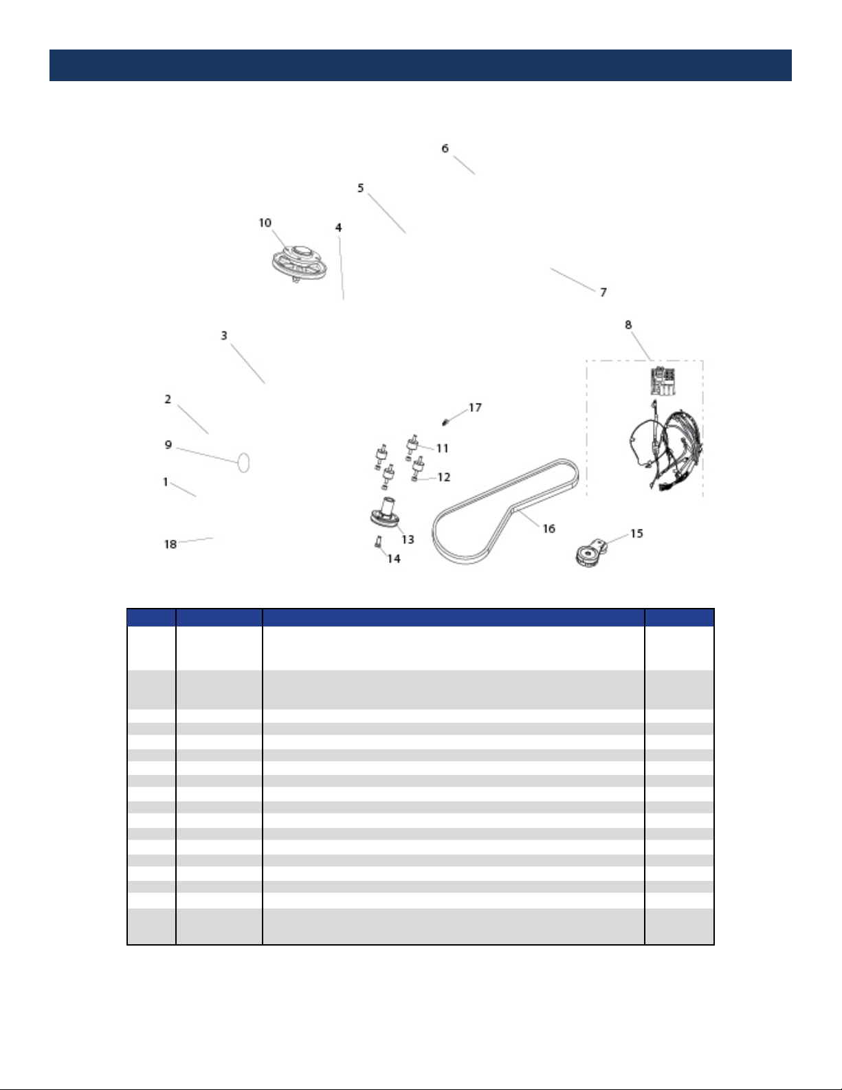
Pad Driver Asm - 27" w/ Hex Hub, Bolt-Lock
Pad Driver Asm - 24" w/ Hex Hub, Bolt-Lock
Pad Driver Asm - 21" w/ Hex Hub, Bolt-Lock
Shroud Asm - 27"
Shroud Asm - 24"
Shroud Asm - 21"
Deck Asm 1
Engine Asm 1
Bottle Carrier Asm 1
Tee Handle Asm 1
Propane Cylinder - 20 lb, RH Thread 1
Electrical Components 1
Shroud Bolt & Spring Assembly 4
Front End Asm 1
Vibration Isolating Spacer - 3/8-16 x M10 4
Nylock Nut - M10, Zinc 4
Engine Pulley Asm 1
Bolt - HCS 7/16-20 X 1.5 Z5 1
Rotary Tensioner Assembly 1
Cogged Belt 1
1/4" P Clamp EDPM Cushion (Secures Throttle Cable) 1
27" General Purpose Burnishing Pad
24" General Purpose Burnishing Pad
21" General Purpose Burnishing Pad
17. ILLUSTRATED PARTS LISTS
UNIT ASSEMBLY
PART NO. DESCRIPTION QTY.
ITEM
1
2
3
4
5
6
7
8
9
10
11
12
13
14
15
16
17
18
W10666
W10667
W10668
W10518
W10522
W10521
W10519
W3132-2
W10363
W10364
W2502
W10520
W10598
W10658
W10366
W10367
W10368
F17159
W10517
WBX51
F0216763
ON40230
ON40224
ON40221
1
1
1
1
1
1
1
1
4
1
4
4
1
1
1
1
1
1

17. ILLUSTRATED PARTS LISTS
OPTIONAL UPGRADES
Clutch System
Operator Presence System
High Emissions Monitoring System
W0091A Emissions Monitor
O2 Oxygen Sensor
Muer Heat Shield Assembly
Headlight Assembly
Dust Bag - 4 Pack
5 Gal Water System
Telescoping Handle System
USB Charging Port & Phone Holster
Drink Bottle & Holder
Metal Pad Driver ASM - Hex Stock Hub, bolt lock
PART NO. DESCRIPTION QTY.
ITEM
1
2
3
3.1
3.2
4
5
6
7
8
9
10
11
W10516
W10527
W10515
W0091A
W2803
W10543
W10544
W10549
W10523
W10536
W10545
W10546
W10669
1
1
1
1
1
1
1
1
1
1
1
1
1

17. ILLUSTRATED PARTS LISTS
ENGINE ASSEMBLY
Propane Solenoid Shuto Valve "Locko", 12V brass 1/4 NPT
Catalyst Muer, Modifed for 708cc
Bracket, Muer Support (708cc Opr Right)
Bracket, Muer Support (708cc Opr Left)
High Pres. Hose ASM - 12 in
Starter Solenoid Relay, 12V
Oil Pressure Switch, SPST, N.O., 1/8 BSP
Oil Drain Valve ASM, 3/8 NPT, with hose
Bracket, Bonnet Filter, 708cc Engine
W10409 | Bonnet Filter - 9.0 ID x 3.25 H
PART NO. DESCRIPTIONITEM
1
2
3A
3B
4
5
6
7
8
9
W10752
W10388-708cc
W11320A
W11320B
W10402
PT-W1305
PT-W1325
W10397
W11362
W10409
Table of contents
Other DiamaPro Systems Floor Machine manuals


 operating instructions")


