INNOVATIVE POOL PRODUCTS CC-400 QT User manual
CC-400 QT
Set Up and User Instructions
Innovative Pool Products LLC. Phone (800) 713-0004 Fax (949) 369-8380
924 Calle Negocio Suite E, San Clemente, CA. 92673 www.InnovativePools.com
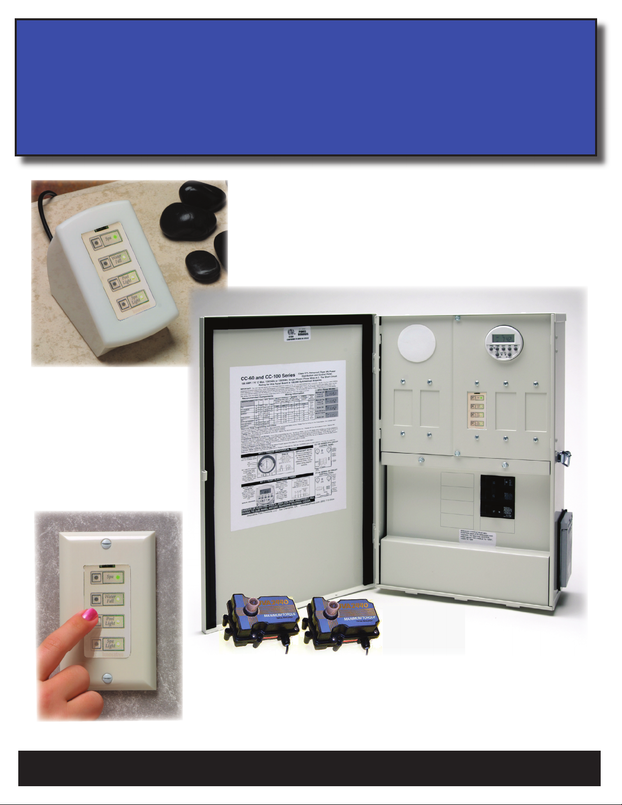
Plug in QT Pedestal
Hardwired QT Controller
CC-400 QT Breaker
Power Center
Please Get This Instruction
Manual to the Home Owner.

Safety Instructions
1. Read and Follow All Instructions
2. This panel should be installed by a qualified electrician in accordance with current I.E.E Wiring Regulations and all National and Local
Electrical Codes. Turn off the Main supply switch before installing the unit to avoid accidents or electrical shock.
3. DANGER - to reduce the risk of injury, do not permit children to use this product unless they are closely supervised at all times.
4. Prolonged immersion in hot water may induce hyperthermia. Hyperthermia occurs when the internal temperature of the body reaches a
level several degrees above the normal body temperature of 98.6 degrees F. The symptoms include dizziness, fainting, drowsiness, lethargy,
and an increase in the internal temperature of the body. The effects of hyperthermia include:
1) Unawareness of impending danger;
2) Failure to perceive heat;
3) Failure to recognize the need to exit the spa;
4) Physical inability to exit the spa;
5) Fetal damage in pregnant women;
6) Unconsciousness resulting in drowning.
WARNING - The use of alcohol, drugs or medication can greatly increase the risk of fatal hyperthermia in hot tubs and spas.
5. Keep Power Center door closed.
6. PLEASE SAVE THESE INSTRUCTIONS.
This Instruction Manual is intended for the following Innovative Pool Products Panels.
CC-60 QT series panels. 4/8 load center, Electronic 7 day programmable timer with battery backup.
UPB functions control Filter Pump relay and Auxilliary One through Three. The Relays are 2 pole single throw 3 horse power rated. This
panel is commonly used on Pool only or Spa only configurations where Valve Actuators are not to be controlled.
CC-100 QT series panels. 8/16 load center, Electronic 7 day programmable timer with battery backup.
UPB functions control Filter Pump relay and Auxilliary One through Three. The Relays are 2 pole single throw 3 horse power rated. This
panel is commonly used on Pool only or Spa only configurations where Valve Actuators are not to be controlled.
CC-400 QT series panels. 8/16 load center, Electronic 7 day programmable timer with battery backup.
UPB functions control Spa Function (Filter Pump relay, Pool Cleaner Cutout, up to 3 Electric Valve Actuators Part # IDA -24, Spa Heater
Thermostat) as well as Auxilliary One through Three. The Relays are 2 pole single throw 3 horse power rated. This panel is commonly
used on Pool / Spa combination configurations where Valve Actuators are necessary to activate the Spa Function. Additional Timer for Pool
Cleaner or 2-speed pump is Optional.
Innovative Pool Products LLC. Phone (800) 713-0004 Fax (949) 369-8380
924 Calle Negocio Suite E, San Clemente, CA. 92673 www.InnovativePools.com

Table of Contents
2. Safety Instructions
2. Innovative Panels these Instructions Cover.
3. Table of Contents
4. Electronic Timer Programming Instructions.
5. QT Module Safety Instructions.
5. Operation
5. Labeling you QT Controller.
6. UPB Configuration
6. Interference from Nieghboring Controllers.
6. Restoring Factory Default Settings.
6. Advanced Settings.
7. Heater Connections.
7. Heater Select Switch.
7. Valve Actuators.
Page 3
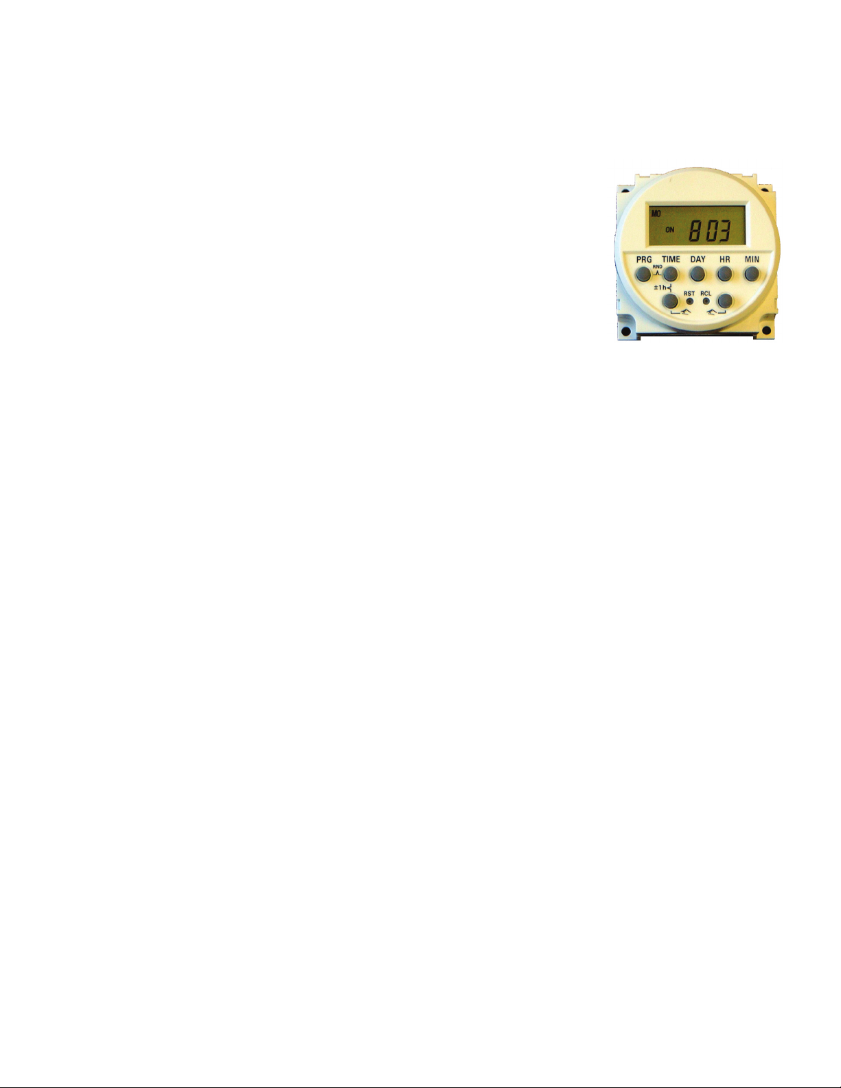
TE501 ELECTRONIC TIMER INSTRUCTIONS
24 HOUR / 7 DAYS DIGITAL TIMER WITH RECHARGEABLE BATTERY BACKUP.
Features
12 memory locations. 6 ON / 6 OFF Summer/winter time change over
Random function Manual override with permanent control or automatic control
Recall function 24 Hours, 7 days, weekday and weekend programming
Operation:
1.1 Power the main BREAKER for approximately 6 minutes to charge unit.
1.2 Use a pointed object (e.g. pencil) to depress “RST” (reset), to clear any data in the programs.
Setting Time / Time correction
Set up the current time before you enter any programming
2.1 Keep “TIME” key depressed while you are setting or correcting the current time and day.
2.2 Depress “DAY” key to advance to the current day.
2.3 Depress “HR” key to advance the hours.
2.4 Depress “MIN” key to advance the minutes.
Programming / Reviewing the On Off time
3.1 Depress the “PRG” key once. You will see PROG 1 on the LCD display which indicates the ON time command to be entered.
3.2 Depress the “DAY” key to choose the day groups that you wish to switch device ON. The day groups will advance in the following sequence:
(ALL DAYS) MO TU WE TH FR SA SU / (INDIVIDUAL DAYS) MO THRU SU / (WEEKDAYS) MO THRU FR /(WEEKENDS) SA SU /
MO THRU SA / MO WE FR / TU TH SA /
3.3 Depress the “HR” key to advance to the hour you choose to power unit ON (AM / PM)
3.4 Depress the “MIN” key to advance the minutes.
3.5 Depress the “PRG” key to advance to the PROG 1 OFF, which indicates the off time command to be entered. (Program as above for on time).
Altogether there are 6 program memory locations that can be used, but one will suffice for the filter pump function.
Be sure to depress the time key after programming/ review of the memory, otherwise the switching times will not execute.
Removing Programs / recall function
4.1 To suspend some of the program memory functions without loosing the information.
4.2 Depress the “PRG” key until the preset memory location that you want to disable appears. Use a pointed object (e.g. pencil) and de
press the “RCL” key, this will clear the preset time but will not erase it from memory. To enable the time, repeat the above steps
Summer / Winter time change
5.1 To change to summer time depress at the same time the “TIM” and “±1h”. The LCD will display a +1h in the upper right corner of the
screen as well as advancing the time one hour.
5.2 Simply repeat this step for winter time change.
Clearing all Programs and times
6.1 Depress, with a pointed object (e.g. pencil) the “RST” key. This will clear all times and on / off programming.
When all the programming is correct, press the “TIME” button to exit program mode. Using either of the lower buttons, place the clock in either “AUTO
ON” (if its time for the pump to be on, or “AUTO OFF” (if its time for the pump to be off). The timer will execute the next ON/OFF time automatically.
Note
If the “PRG” and “TIM” keys are pressed at the same time, it will enable the random function of the clock. The program times that you have programmed
will execute with a random delay of from 2 to 32 minutes. Normally this would not be a function that you would want your pool equipment to run on. If
it has been enabled there will be a “RND” indicator on the upper right side of the LCD. To turn it off simply depress the “PRG” and “TIM” keys again.
Cleaner or 2-SPEED PUMP TIMER
The Cleaner Timer or 2-Speed Pump timer are OPTIONAL Equipment and are installed in the Left Timer Panel of the CC-400 Control Panel. A wiring
Harness is provided in all CC-400 panels for the Timer Wiring. These devices will automatically be suspended when the SPA FUNCTION is activated. Set
the ON and OFF times for periods when the Filter Pump Timer is set to be ON. Allow 15 minutes of prime cycle time before you set the Cleaner to run.
Page 4
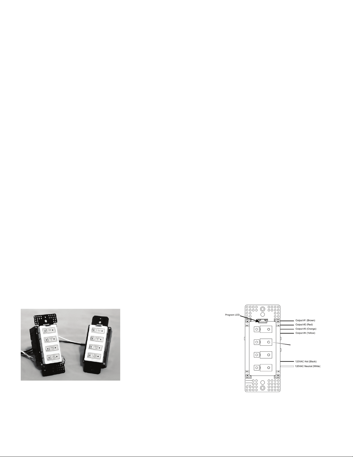
QT Module
FUNCTION
The Quad Output Module, model UCQ-20, controls four 120VAC, 150W loads based on digital commands received
over the power wiring from a Universal Powerline Bus (UPB) controller. Electrical devices connected to the UCQ
can be turned ON and OFF using local pushbuttons, or remotely from a model UCQT-20 transmitter or other control-
ler. UPB controllers and modules can be freely located anywhere in the home. No communication wiring is required
and no radio frequency signals are used.
IMPORTANT SAFETY INSTRUCTIONS
When using electrical products, basic safety precautions should always be followed, including the following:
1. READ AND FOLLOW ALL SAFETY INSTRUCTIONS.
2. Keep away from water. If product comes into contact with water or other liquid, unplug immediately.
3. Never use products that have been dropped or damaged.
4. Do not use this product for other than its intended use.
5. Do not insert metal objects into the module while it is connected to power.
6. To avoid risk of fire, burns, personal injury and electric shock, install this product out of reach of small children.
7. Do not cover the product with cloth, paper or any material when in use.
8. SAVE THESE INSTRUCTIONS.
INSTALLATION
The QT Quad Module is wired into the CC series electrical panel. Devices that are to be controlled by the QT Quad
Module must be connected between directly to the relays the QT Quad Module controls. The Relays are rated at 2
pole 240 volt 25 amp 3hp. Do not excede the specifications of the relay.
IMPORTANT:
The output of QT Quad Module is 120 volts. Each output circuit is rated at a Maximum of 150 watts. The QT Quad
Module is intended to switch the coil of the relay only and is not intended to switch inductive or resistive loads di-
rectly. Failure to use the QT Quad Module correctly will void the warranty of the product.
OPERATION
The four outputs of the UCQ can be controlled in two ways:
1. Via the four pushbuttons on the faceplate, or
2. Via UPB commands received over the powerline from a linked controller ( QT Quad Module Transciever)
The Status LEDs next to each pushbutton will illuminate when the respective output is ON, and extinguish when the
output is OFF.
Button #1
Button #2
Button #3
Button #4
LABELING THE SWITCHES
The QT Quad Module ships with generic blank labels on switches 1-4. Please Label these switches by removing the
Insert on the label where the + sign is and carefully replacing it with the appropriate label from the label pack pro-
vided with each unit. Button #1 is at the top closest to the Programming LED. Match the labels on both the indoor
and outdoor units.
Label Area
Page 5

CONFIGURATION
Units from the factory are pre-configured and should operate with linked controllers “out-of-the-box.”
INTERFERENCE FROM NEIGHBORING CONTROLLERS
The QT Modules are set from the Factory to the following Default Settings
Network Name “Network 1”
Room Name “New Room Name”
Device Name “New UCQ”
Unit ID 26
Network ID 255
Network Password 1234
THIS MEANS THAT IF YOU DONʼT CHANGE YOUR NETWORK ID AND
YOUR NEIGHBOR DOESNʼT CHANGE HIS NETWORK ID THEY WILL
INTERFERE WITH ONE ANOTHER
RESTORING UPB FACTORY DEFAULT SETTINGS
To restore the default settings, place the UCQ in SETUP mode and then press any pushbutton ten times. Press the
button twice again to exit this mode.
ADVANCED SETTINGS
Advanced configuration requires UPB configuration software (e.g., UPStart) and a model UMC Computer Interface.
Please refer to the software documentation for information on advanced configuration options.
IMPORTANT
PLEASE SCAN AND RESET YOUR NETWORK ID
The UCQ has the capability to automatically set a unique Network ID for itself and other UPB devices. This fea-
ture is useful when adjacent homes are being outfitted with the same hardware.
To manually set a unique Network ID, place all devices that are to share this ID into SETUP mode in order to initi-
ate self-identification on the powerline. To place the QT Modules in SETUP mode, press the TOP button five times
rapidly. The Program LED will continuously blink GREEN when the unit is in SETUP mode. If you are in bright
sunlight shade the LED and verify that it is in the SETUP mode.
Once all devices are in SETUP mode, press the middle two buttons of the Indoor QT Module Controller simulta-
neously. The Program LED will blink at twice its normal rate. The Indoor QT Module Controller will find an
unused Network ID and will program all QT modules in Setup Mode to this “unused” Network ID. After success-
ful completion, the Program LED will return to its normal state.
You have now verified that your installation is on a Unique Network ID. This Network ID is not used by other
homes in your area. To insure that other New Installations will not be set to Your Network ID you must leave the
controller (either in the home or at the pool equipment) powered up. This way when the next installation occurs the
Neighboring System will see your deviceʼs Network ID and set itself to the Next Available Network ID.
Page 6

Heater Connections
See Heater Manufacturers Instruction on how to connect a 3 wire remote system to that particular heater you have installed. These instruc-
tions vare from one manufacturer to another and from one model to another.
The Low Voltage Conductors for the Heater Thermostats must conform to the following.
Remote Wiring must be in a separate conduit from High Voltage Conductors.
Remote Wiring must not be run parrallel to High Voltage Conductors.
For less than 30 feet the wires should be stranded with a minimum 22 AWG (See Heater Manfacturers Instructions)
Some Heaters require an adapter wiring harness available from the Heater Manufacturer.
The CC-400 QT is a simple control system that controls the Heater via a 3 wire remote connection. The 3 Low Voltage Wires are connect-
ed to the Common, Low (POOL), or High (Spa) thermostats on the Heater. Connect the CC-400 QT to the Heater and to the 3 wire screw
terminal connection on the CC-400 QTʼs PC board inside the Upper Left Compartment of the CC-400 QT panel at the Pool Equipment.
The 3 screw terminals are labeled S for SPA or the High Thermostat , P for Pool or the Low Thermostat and C for Common.
The CC-400 uses the Pool Heaters Thermostats. You must set these thermostats to the desired temperature.
Heater Select Switch
The Heater Select switch allows you the Heat your Swimming Pool to your desired temperature during daily filtration. For this function
turn the Heater Select Switch to the Heat Pool and Spa position and the heater will be allowed to fire to the Low Thermostat setting during
Normal Pool Filtration.
If you do not want to heat your swimming pool daily you must turn the Heater Select Switch to the Heat Spa Only. When the Heater Se-
lect Switch is in the Heat Spa Only position the Pool will not heat daild during filtration and the Spa will Automatically Heat to the Heaters
High Thermostat setting when the Spa Switch is activated via the QT controller either in the house or at the CC-400 QT panel.
Valve Actuator
The CC-400 switches all 3 Valve Actuator Sockets from Pool to Spa at the same time when the Spa Function is activated by a QT control-
ler either at the CC-400 QT panel or in the Home.
The Valve Actuators cannot be activated independently.
Plug the Valve Actuators into the 3 pin Sockets on the PC board in the upper left compartment of the CC-400 panel.
Mount the Valve Actuators to the appropriate valve using the screws provided.
Mount the Valve Actuator so that during the swing of the Actuator the common port of the 3 way diverter valve is not blocked by the
diverter. Failure to mount the valve actuator correctly could damage your pool equipment and create a dangerous high pressure condition
that could cause injury.
Check the Valve Actuator for proper rotation and operation by using the switch on the valve actuator before using turning on the filter
pump.
Page 7
Table of contents


