Innovative MPE33-2 User manual

33" Electric Fireplace
MODEL:
SAVE THESE INSTRUCTIONS
FOR FUTURE REFERENCE
This manual will enable you to obtain a safe, efficient and dependable
installation and operation of your electric fireplace. Please read and
understand these instructions before beginning your installation.
Do not alter or modify this fireplace or its components under any circum-
stances. Any modification or alteration of the fireplace system, including
but not limited to the fireplace and accessories, may void the warranty,
listings and approvals of this system and could result in an unsafe and
potentially dangerous installation.
IMPORTANT! IF OPTIONAL GLASS DOORS ARE PURCHASED, TO
ASSURE PROPER ALIGNMENT, INSTALL THIS FIREPLACE IN A
SQUAREANDPLUMBCONDITION,USINGSHIMSASNECESSARY
AT SIDES. THIS APPLIANCE IS MOUNTED ON RUBBER FEET TO
ENSURE ADEQUATE AIR CIRCULATION BENEATH FIREPLACE.
DO NOT BLOCK AIRFLOW AT THE BOTTOM AIR INTAKES.
INSTALLER: DO NOT DISCARD THIS MANUAL
PLEASE LEAVE FOR THE HOMEOWNER
FOR YOUR SAFETY
DO NOT STORE OR USE GASOLINE OR OTHER FLAMMABLE
VAPORS AND LIQUIDS IN THE VICINITY OF THIS OR ANY OTHER
APPLIANCE.
electric fireplaces are designed for use as a decora-
tive appliance and/or as a supplemental heater. They are
not intended for continuous use as a primary heat source.
A French manual is available upon request. Order P/N 850,032CF
Ce manuel d’installation est disponible en francais, simplement en
faire la demande. Numéro de la pièce 850,032CF.
INSTALLATION AND
OPERATION INSTRUCTIONS
Report # C1482763
2
CUS
®
DrAFt
06-06-06
Publication:506009-10
Innovative Hearth Products
MPE33-2,ERT3033,Capella 33

NOTE: DIAGRAMS & ILLUSTRATIONS NOT TO SCALE.
2
IMPORTANT SAFETY AND
WARNIING INFORMATION
READ THIS MANUAL IN ITS
ENTIRETY AND UNDERSTAND
THESE RULES TO FOLLOW FOR
SAFETY.
TO PREVENT A POSSIBLE FIRE,
DO NOT BLOCK AIR INTAKES OR
EXHAUSTS IN ANY WAY. DO NOT
USE NEAR SOFT SURFACES, LIKE
A PILLOW, WHERE OPENINGS MAY
BECOME BLOCKED.
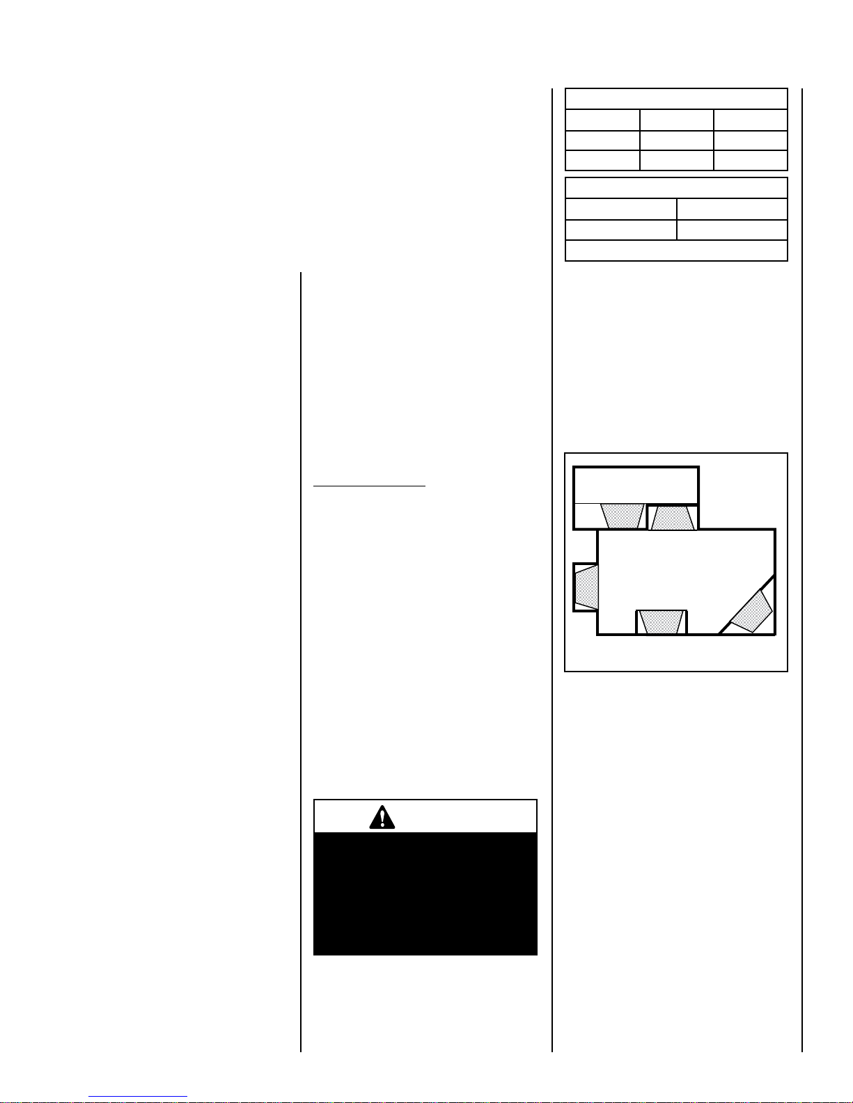
THIS APPLIANCE MAY BECOME HOT
WHEN IN USE. TO AVOID BURNS, DO
NOT LET BARE SKIN TOUCH HOT SUR-
FACES. KEEP COMBUSTIBLE MATERI-
ALS, SUCH AS FURNITURE, PILLOWS,
BEDDING, PAPERS, CLOTHES AND
CURTAINS AT LEAST 3 FEET (1 METER)
FROM THE FRONT OF THIS APPLI-
ANCE.
DO NOT OPERATE ANY HEATER WITH
DAMAGED WIRING OR CONNECTORS,
OR AFTER THE APPLIANCE MALFUNC-
TIONS, OR IF IT HAS BEEN DROPPED
OR DAMAGED IN ANY WAY.
ANY REPAIRS TO THIS FIREPLACE
SHOULD BE PERFORMED BY A QUALI-
FIED SERVICE TECHNICIAN.
WARNING
If the information in this manual
is not followed exactly, an elec-
trical shock or fire may result
causing property damage, per-
sonal injury or loss of life.
IMPORTANT
Before starting your fireplace
installation, read this instal-
lation and operation manual
very carefully to ensure you
understand it completely and in
entirety. Failure to follow these
instructions may result in a pos-
sible electric shock, fire hazard
and/orinjuryor propertydamage
and will void the warranty.
CAUTION
This appliance is mounted on
rubberfeet. Thepurpose ofthese
feet is to ensure adequate air
circulationbeneaththefireplace.
Do not remove these feet. Do not
install the fireplace directly onto
acarpet, rug,furnitureorsimilar
surfaces, which could hinder or
block the airflow.
CAUTION
Extreme caution is necessary
when any heater is used by or
near children or invalids and
whenever the heater is left oper-
ating and unattended.
UNDER NO CIRCUMSTANCES SHOULD
THIS FIREPLACE BE MODIFIED. PARTS
HAVING TO BE REMOVED FOR SERVIC-
ING MUST BE REPLACED PRIOR TO
OPERATING THE FIREPLACE AGAIN.
DO NOT USE THIS APPLIANCE OUT-
DOORS. DO NOT EXPOSE FIREPLACE
TO THE ELEMENTS (SUCH AS RAIN,
ETC.).
THIS APPLIANCE IS NOT INTENDED
FOR USE IN BATHROOMS, LAUNDRY
AREAS OR SIMILAR INDOOR LOCA-
TIONS. NEVER LOCATE THIS APPLI-
ANCE WHERE IT COULD FALL INTO
A BATHTUB OR OTHER WATER CON-
TAINER.
DO NOT RUN ELECTRICAL WIRING OR
POWER CORD UNDER CARPETING. OR
COVER WITH THROW RUGS, RUNNERS
OR SIMILAR MATERIALS.
FOR 120 VAC POWER CORD AVOID THE
USE OF AN EXTENSION CORD BECAUSE
THE EXTENSION CORD MAY OVERHEAT
AND CAUSE A RISK OF FIRE. HOW-
EVER, IF YOU HAVE TO USE AN EXTEN-
SION CORD, THE CORD SHALL BE NO.
14 AWG MINIMUM SIZE AND RATED
NOT LESS THAN 1800 WATTS, 15
AMPS. THE EXTENSION CORD MUST
BE A THREE CONDUCTOR SHEATH
CABLE WITH GROUNDING TYPE PLUG
AND CORD CONNECTION.
THIS APPLIANCE HAS HOT AND ARCING
OR SPARKING PARTS INSIDE. DO NOT
USE IT IN AREAS WHERE GASOLINE,
PAINT OR FLAMMABLE LIQUIDS ARE
USED OR STORED.
THIS FIREPLACE SHOULD NOT BE USED
AS A DRYING RACK FOR CLOTHING, NOR
SHOULD CHRISTMAS STOCKINGS OR
OTHER DECORATIONS BE HUNG NEAR IT.
USE THIS APPLIANCE ONLY AS
DESCRIBED IN THIS MANUAL. ANY
OTHER USE IS NOT RECOMMENDED BY
THE MANUFACTURER AND MAY CAUSE
A FIRE, ELECTRIC SHOCK OR INJURY
TO PERSONS.
IF APPLIANCE IS TO BE DISCON-
NECTED, TURN OFF CONTROLS FIRST.
DO NOT INSERT OR ALLOW FOREIGN
OBJECTS TO ENTER ANY VENTILATION
OR EXHAUST OPENING, AS THIS MAY
CAUSE AN ELECTRIC SHOCK, FIRE, OR
DAMAGE TO THE APPLIANCE.
SAVE THESE INSTRUCTIONS.
WARNING
To prevent contact with sag-
ging or loose insulation, the
appliance must not be installed
againstvaporbarriersorexposed
insulation. Localized overheat-
ing could occur and a fire could
result. Insulation and a vapor
barrier should be placed a
minimum of 2 inches from the
appliance.
IMPORTANT
Cold climate installation recom-
mendation: when installing this
fireplaceagainstanon-insulated
exterior wall or chase, it is
mandatory that the outer walls
be insulated to conform to appli-
cable insulation codes.
IMPORTANT
These fireplaces are designed
assupplementalheaters.There-
fore, it is advisable to have an
alternate heat source when
installed in a dwelling.

NOTE: DIAGRAMS & ILLUSTRATIONS NOT TO SCALE.
33
Installation must conform to local codes.
In the absence of local codes, electrical
wiring and grounding must comply with
the National Electrical Code ANSI/ NFPA
70 - latest edition. In Canada, the cur-
rent CSA C22-1 Canadian Electrical Code
- latest edition.
CONGRATULATIONS!
In selecting this Merit electric fireplace, you have chosen the finest and
most dependable fireplace found anywhere. A beautiful and prestigious addition to
the finest homes. Welcome to a Family of hundreds of thousands of satisfied
SuperiorNOXFireplace Owners.
Please read and carefully follow all of the instructions found in this manual. Please
pay special attention to the safety instructions provided in this manual. The instruc-
tions included here will assure that you have many years of dependable and enjoyable
servfice from your product.
TABLE OF CONTENTS
Important Safety Information. Page 2
Packaging List. Page 3
Introduction . Page 3
General Information . Page 3
Locating Fireplace. Page 3
Tools/Supplies Required . Page 3
Framing Specifications. Page 4
Fireplace Specifications. Page 4
Clearances . Page 5
Pre-installation. Page 5
Installation Steps . Page 5
Electrical Connections. Page 5
Final Finishing. Page 6
Break-In Period. Page 6
Control Panel Operation. Page 6
Remote Control Operation . Page 7
Maintenance. Page 8
Wiring Diagrams. Page 9
Troubleshooting . Page 14
Replacement Parts. Page 15
Optional Accessories. Page 17
PACKAGING LIST
This assembled Electric Room Heater is
packaged with:
• One accessory package located in the
firebox, containing;
1. One Installation and Operation Manual.
2. One Warranty Certificate.
3. One Remote Control.
INTRODUCTION
This Electric Fireplace is designed for
residential applications to be framed in
as a fireplace.
This appliance has been tested in accor-
dance with UL 2021 and CSA C22.2 No.
46-M198 standards for fixed and location
dedicated electric room heaters.
WARNING
Do not install or operate this fire-
placethroughaswitchwiredinthe
120 VAC or 240 VAC circuits. The
only approved wiring for a switch
is through the low voltage circuit
(24 VAC) as shown on Page 14.
GENERAL INFORMATION
Power Supply Wire Specifications
120 Volt, 60 Hz, 1600 Watts:
(ref. Page 9)
Hard Wire Connection - Use two conductor,
non-metallic sheath cable with ground wire
(total three wires) for the incoming power
supply. The wire used must conform to local
and national electrical codes for the specified
power consumption rating. See Table 1.
240 Volt, 60 Hz, 3000 Watt:
(ref. Page 10)
Use three conductor, non-metallic sheath cable
with ground wire (total four wires) for the
incoming power supply. The wire used must
conform to local and national electrical codes
for the specified power consumption rating.
See Table 1.
Wall Switch or Wall Thermostat Kits
(optional kits, see Page 17)
Low voltage wire is provided for the wall switch
connection. The wires gage requirements are
shown on Table 1.
Power Supply Wire Gage
Voltage Wire Gage Fuse
120 V 14 GA. 15 AMP
240 V 14 GA. 20 AMP
Wall Switch / Thermostat Wire Gage
Voltage Wire Gage
5 VOLTS 18 GAGE
Table 1
Figure 1
LOCATING YOUR MERIT ELECTRIC
FIREPLACE
Your new fireplace maybeinstalledintoexisting
framing or built into a wall (see Figure 1).
When choosing a location for your new fire-
place, ensure that the general instructions are
followed. Also, for the best effect, install the
fireplace out of direct sunlight and away from
overhead lighting. See Figure 1.
fireplace shown in gray.
TOOLS AND BUILDING SUPPLIES
NORMALLY REQUIRED
TOOLS:
Phillips Screwdriver
7/16" Socket Drive
Hammer
Saw And/or Saber Saw
Level
Measuring Tape
Plumb Line
Electric Drill And Bits
Pliers
Square
Gloves
IMPORTANT NOTE: This fireplace system
is not difficult to install. However, in the
interest of safety, it is recommended that
the installer be a qualified or certified
“tradesman” familiar with commonly
accepted fireplace installation and safety
techniques as well as prevailing local
codes.
BUILDING SUPPLIES:
Framing Materials
Wall Finishing Materials
Caulking Materials
(noncombustible)
Top View Showing Approved
Room Locations of Fireplace

NOTE: DIAGRAMS & ILLUSTRATIONS NOT TO SCALE.
4
FRAMING SPECIFICATIONS
34-1/2"
(876 mm)
21-1/8 "
(537 mm)
14-7/8"
(37
8
mm)
5-1/8 "
(130 mm)
33 "
(838 mm)
2-1/4 "
(55 mm)
29-3/4 "
(754 mm)
32 "
(812 mm)
Front View
Top View
Right Side
Left Side
13-3/4"
(350 mm)
5-1/4 "
(134 mm)
24-1/2"
(
622 mm
)
27-1/2 "
(
700 mm
)
21-1/8 "
(537 mm)
Electrical Access
Cover
Power Cord
Electrical Access
FIREPLACE SPECIFICATIONS
Front View
Side View
36-1/4 "
(921 mm)
25-5/8 "
35-1/4 "
(651 mm)
(895 mm)
51-1/4 "
(1302 mm)
32 "
(812 mm)
4 "
(102 mm) 15-1/8 "
(384 mm)
Corner View
Electrical
(left side)
Junction
Box
Electrical
Junction
Box
35-1/4 "
(895 mm)
Figure 2
Figure 3
Note: Framing dimensions are calculated for a nailing flange depth of 1/2"

NOTE: DIAGRAMS & ILLUSTRATIONS NOT TO SCALE. 5
MINIMUM CLEARANCES TO COMBUS-
TIBLES
Mantel Clearance: Combustible and Non-com-
bustible mantels may be installed at any height
above the top of the face of fireplace.
Model: MPE33-2,ERT3033.Capella 33
Description: Merit Electric Fireplace,
33” Radiant
Shipping Weight: 81 lb.'s (36.75 KG)
Packaging:
41” x 17 3/4” x 33 1/2”
(1040 mm x 451 mm x 850 mm)
14.1 cu. ft.
Power Requirements:
(120 Volt, 60 Hz.)
Rated Wattage - 1600 Watts
Amperage - 13.33 Amps
(240 Volt, 60 Hz.)
Rated Wattage - 3000 Watts
Amperage - 12.5 Amps
Blower CFM: 83 CFM
(120 V): 5,461 BTU/HR
(240 V): 10,239 BTU/HR
FIREPLACE SPECIFICATIONS
This appliance is an electric fireplace designed
to be framed in with combustible materials (up
to the edge of the appliance). A drywall lip at
the top of the fireplace and 4 nailing flanges
on the sides of the appliance is provided to
facilitate installation.
Hearth Protection: A hearth is not mandatory,
but it is recommended for aesthetic purposes.
Secure the hearth extension to the floor to
prevent possible shifting. Do no block the air-
flow beneath the appliance (read the following
WARNING).
Clearances
Sides 0 inches - 0 mm
Floor 0 inches - 0 mm
Top 0 inches - 0 mm
Table 2
WARNING
Electrical wiring must comply
with local building codes and
other applicable regulations to
reduce the risk of fire, electrical
shock and injury to individuals.
IMPORTANT
Any electrical re-wiring of this
appliance must be done by a
qualified electrician.
WARNING
Do not use this fireplace if any
part of it has been underwater.
Immediately call a qualified
service technician to inspect the
fireplace and replace any part of
the electrical system which has
been under water.
3. Wire a dedicated, properly fused circuit with
an Amp rating for the appropriate voltage
(120 V - 15 Amps or 240 V - 20 Amps).
A dedicated circuit is required to prevent
overloadingahousecircuitincases of having
multiple appliances on the same circuit.
Use an outlet that is protected by a ground
fault circuit interrupter where required by
electrical code.
4. (If applicable) Make wall mount wall switch
or wall thermostat connections as outlined
on Pages 10& 11.
5. Perform a function test. See Manual Control
Panel Operation on Page 6 and Remote
Control Operation on Page 7.
ELECTRICAL CONNECTIONS
Refer to the electrical diagrams on Pages 9
to 13
PRE-INSTALLATION
Before You Start
Check appliance for any concealed damage.
DETAILED INSTALLATION STEPS
1. Complete the framing opening to the dimen-
sions specified in Figure 2.
2. Prepare the connections to power source:
120 Volt Connections - Locate the power
cord on the left side of the unit and connect
it to the outlet installed during the framing
(see Figure 2).Verify that the power to the
receptacle is off.
Hard wired installation:
Ensure that there is a minimum of 8" of the
service cable for connection to the junction
box on the fireplace.
- Loosen four screwstoremove the junction
box cover plate.
- Disconnect and removethe 120 Voltpower
cord from the fireplace wires.
- Position the fireplace into the framed-in
opening. Attach fireplace to frame using
nailing flanges provided.
- Complete the wiring to the fireplace as
shown on Page 9.
- Place allwire connectors insidethe junction
box.
- Attach junction box cover plate with four
screws.
240 Volt Connections - Ensure that there
is a minimum of 8" of the service cable
for connection to the junction box on the
fireplace.
- Loosen four screwstoremove the junction
box cover plate.
- Disconnect and removethe 120 Voltpower
cord from the fireplace wires.
- Position the fireplace into the framed-in
opening. Attach fireplace to frame using
nailing flanges provided.
- Complete the wiring to the fireplace as
shown on Page 10.
- Place allwire connectors insidethe junction
box.
- Attach junction box cover plate with four
screws.
The fireplace wires L1, L2, N, N1, N2 and
G are attached to the rear of the junction
box cable clamp for easy access.

NOTE: DIAGRAMS & ILLUSTRATIONS NOT TO SCALE.
6
MANUAL CONTROL PANEL
Main Power On/Off (rear most switch)
Figure 4
FINAL FINISHING
Materials such as brick and tile can be
extended down to the top of the fireplace. Do
not extend down, covering the outlet or glass
enclosure panel (optional kit).
There are a wide variety of “finished looks” for
these fireplaces, from formal wall decor with
elaborate mantels to rustic wood paneling or
warm brick facings.
Accent Trim Installations
An optional accent trim kit is available from
your dealer (see Page 17). These options give
the appliance an attractive finished look.
Hearth
An aesthetically pleasing fireplace hearth can
be installed, if desired (see hearth protection
on Page 5).
BREAK-IN PERIOD:
During the first few initial uses of this heater,
there may be a release of a slight, harmless
odor. This odor is a normal occurrence caused
by the initial heating of the internal heating
elements and should not reoccur.
MANUAL CONTROL PANEL OPERATION
(refer to Figures 5 & 6)
Once this appliance has been properly installed
and connected to the power supply as defined
in this manual, it is ready to operate.
Flame / Ember On/Off (front most switch)
Figure 5
On
On
On Off
Off
Off
Heater On/Off (center switch)
Manual Control Switches
are located behind pull
screen on inside floor
Note: Ensure the circuit breakers for the power
supply are turned on.
This appliance can be operated either from the
manual control panel (see Figures 4 & 5)or
by using the remote control, wall switch or wall
thermostat (optional kits).
The manual controls are located on the firebox
floor on the front left (see Figure 5). If an
optional glass enclosure is installed, it must
be removed to access.
Main Power ON/OFF Switch
Whenthe main powerswitch is turnedon, power
is supplied to the fireplace. This switch must be
on for all other switches to operate.
Heater ON/OFF Switch
When this switch is turned on, the heater will
emitheat in the temperature range selected (see
Figure 6; G, H & I). The fireplace can operate
with or without heat.
Flame / Ember On/Off Switch:
Turns lights on inside ember bed and flame
cylinder.
• When using the main power on/off switch
inside the manual control panel, the power
on/off switch outside the manual control
panel (optional wall switch kit) must be in
the OFF position.
• When using power on/off switch outside
the manual control panel (optional wall
switch), the power on/off switch inside the
manual control panel must be in the OFF
position.
• When using the remote control, the power
on/off switch inside the manual control
panel and the wall switch (optional kit)
must be on the OFF position.

NOTE: DIAGRAMS & ILLUSTRATIONS NOT TO SCALE. 7
• When using the remote control, the power
on/off switch inside the body and the wall
switch (optional kit) must be on the OFF
position.
REMOTE CONTROL OPERATION:
Figure 6
The Electric Fireplace is provided with
an Infrared light Remote Control. All functions
of the fireplace can be con-trolled through
the remote control. Note: The Effective range
of the remote control is up to approximately
26 feet (8 meters).
The functions identified on the remote (see
Figure 6)are as follows:
A. POWER BUTTON
Press once to turn on power to fireplace.
B. INDICATING LIGHT
Illuminates when signal is sent.
C. LIGHT BUTTON
On/off switch for flame and ember light.
D. LIGHT ADJUSTING BUTTON (DIM)
Reduces brightness of embers.
E. LIGHT ADJUSTING BUTTON (BRIGHTEN)
Increases brightness of embers.
F. HEATER ON/OFF
This button will turn the heater ON and OFF
independent of the main button.
G.TEMPERATURE ADJUSTMENT BUTTON
(HIGH)
Highest heat output, up to 86° F.
H.TEMPERATURE ADJUSTMENT BUTTON
(MED.)
Medium heat output, up to 75° F.
I. TEMPERATURE ADJUSTMENT BUTTON
(LOW)
Lowest heat output, up to 64° F.
J. FLAME ADJUSTING BUTTON (LOWER)
Reduces flame intensity.
K. FLAME ADJUSTING BUTTON (HIGHER)
Increases flame intensity.
Remote Control Operation Steps:
1. To control the electric fireplace by remote
control, the main power on/off switch
should be in the off position. This switch is
located on the front left floor of firebox (see
Figures 4 & 5).
2. When operating the remote control, it must
be pointed at the logs inside the electric
fireplace and a beep must be heard each time
you press a function button. The beep lets
you know the remote control is operating the
function button you are pressing.
3. Remote On/Off Button - The button on the
top left (see A) is the on/off power button.
When pressing this button you will hear a
beep, this will activates the power to the
fireplace. You must then press the display
button (C) to activate the lights.
Note: If the flame does not come on immedi-
ately, adjust brightness and intensity (buttons
E & K).
4. To increase the brightness, press and
release the light brighten button (see E).
Each time you press this button you will
heara beep, and thebrightness will increase
slightly until the maximum brightness
is achieved. To decrease the brightness,
press and release the light dimming button
(see D). Each time you press this button
you will hear a beep, and the brightness
will decrease slightly until the minimum
brightness is achieved.
5. Heater Button - To activate the heater, press
the heater button (see F), then press HI
(G),
MED (H), or LO (I). The heater is preset to
the following temperatures:
• HIGH will shut off when room reaches
approximately 86° F (30° C).
• MED. will shut off when room reaches
approximately 75° F (24° C).
• LO. (Low) will shut of when room reaches
approximately 64° F (18° C).
6. Flame Button - Press the Flame Adjusting
Buttons to achieve a higher or lower flame
intensity (see J & K).
8. To turn the electric fireplace off, Press the
On/Off button once (A), when you hear the
beep the fireplace will be completely off.
When you restart your fireplace with the
remote control, all settings will restart at the
high settings programmed at the factory. You
may also simply press the (C) button to turn
off the flame and still use the heater.
REMOTE CONTROL
CAUTIONS
• Do Not Use Old Batteries With
New Ones.
• Do Not Use Batteries Other That
The Type Specified (2 Ea. AA).
• Ensure Batteries Are Correctly
Installed In Remote Control.
(J) button:If you need Yellow Flame, you
need touch the FLAME BLUE button It
controls Blue LED Brightness, Total 6
setting. It will be let Blue Flame from
Biggest to disappear. Then It only left
Yellow Flame on the fire surface. If touch
repeated. (K) button:If you need Blue
Flame, you need touch the FLAME
YELLOWbutton. It controls Yellow LED
Brightness, Total 6 setting. It will be let
Yellow Flame from Biggest to disappear.
Then It only left Blue Flame on the fire
surface.
7.
POWER
ON/OFF
ON/OFF
DISPLAY
Dimmer Brighter
EMBERS
HEATER ON/OFF
TEMP. CONTROL
HIGH MED. LOW
FLAME
BLUE YELLOW
Ab
C
E
F
D
H
GI
JK

NOTE: DIAGRAMS & ILLUSTRATIONS NOT TO SCALE.
8
Figure 9
MAINTENANCE
This appliance has been designed to provide
many years of trouble-free service. The com-
ponents that will need to be serviced have been
kept to a minimum. Periodic dusting of the
fireplace is all that should be required.
HEATER/BLOWER REPLACEMENT PROCE-
DURE
1. Turn off power to the fireplace.
2. Let the fireplace completely cool, if it has
been operating.
3. Open the screens (remove glass panel
enclosure, if applicable).
Blower / Heater
Figure 11
Figure 10
Figure 8
4. OPTIONAL: To ensure that the brick panel
isn't accidentally scratched, you may wish
to remove it before proceeding:
Mirror glass Removal Procedure:
a. Remove the 2 screws on the front of the
grate. Remove Grate (see Figure 8).
b. Lift out Log / Ember assembly and set
aside. Caution: Be careful not to scratch
the finish.
c. Remove the top Mirror glass retaining
bracket (see Figure 15). Be very careful
to hold the bracket when removing the
2 screws to ensure the bracket doesn't
fall.
d. Remove the left and right side mirror
glass retaining brackets (see Figure
15). Be very careful to hold the bracket
when removing. Remove the bottom
screw first to avoid the frame falling
down after both screws are removed.
TAKE CARE TO HOLD MIRROR GLASS
IN PLACE TO PREVENT POSSIBLE
DAMAGE.
Suggestion: Slide the screens toward
the middle of the fireplace for easier
access to the screws on the sides.
Return the screens to the sides before
proceeding to instruction e.
e. Tip mirror glass forward from the top,
just enough to clear screens. Carefully
remove brick panel from firebox and set
aside in a safe place.
5. Remove the screws which secure the heater
blower mounting plate using a phillips screw-
driver as follows (see Figures 9 & 10):
a. While using one hand to hold the handle
ofthe heater/blowerassembly (seeFigure
9), remove the 5 screws which secure
the mounting plate. Remove the 4 side
screws first (2 on each side). Remove
the middle screw that is on the top of
the handle last.
b. Slowly lower the heater/blower assembly
and let it rest on the 2 support chains
(1 on each side).
IMPORTANT NOTE: Label all wire
locations prior to disconnecting to
ensure that wires are reconnected in
the correct positions.
6. Replace the heater/blower as follows:
a. Replace the old heater/blower with the
new one. Note: when replacing the
heater/blower, ensure that all the wires
on the heater are correct, otherwise the
heater will not function properly.
b. Turn the power and heater switches on
and check for proper operation.
c. Turn off power to the fireplace.
d. Using one hand to hold the handle of the
heater/blower assembly, slowly push it
back up and line up the holes for the 5
screws. Install the 5 screws to secure
the new heater/blower assembly to the
mounting plate.
7. (If mirror glass was removed)Reverse
instructions on Step 4.
8. Reinstall glass panel enclosure, if appli-
cable.
Handle
Heater/blower Mounting Plate
Mirrorglass
Panel
Remove screws indicated by arrows
Heater/blower Mounting Plate
Be careful not to
damage mirror glass
Grate
WARNING
An authorized service represen-
tative should perform any other
servicing.
CAUTION
Handle glass very carefully to
prevent accidental breakage.
CAUTION
Do not use abrasive cleaners on
the glass panel. Do not spray
liquids directly onto any surface
of the fireplace.
WARNING
When cleaning the fireplace, the
fireplace must be cool.
CLEANING THE GLASS ENCLOSURE
PANEL (OPTIONAL KIT)
Over time the front glass panel may become
dirty or dusty. Dust can be removed by lightly
rubbing the glass surface with a clean, lint free
cloth or paper towel. To remove fingerprints
or other marks, use a damp cloth with a good
quality household glass cleaner. The front glass
panel should be completely dried with a clean,
lint free cloth or paper towel.
CAUTION
Disconnect power before
attempting any maintenance or
cleaning to reduce the risk of
fire, electrical shock or personal
injury.

NOTE: DIAGRAMS & ILLUSTRATIONS NOT TO SCALE.
10
9
WIRING DIAGRAM - 120 VOLT
Wiring diagrams are provided here for reference purposes only. This information is also provided on schematics attached directly to the appliance
on the left side.
CAUTION: LABEL ALL WIRES PRIOR TO DISCONNECTION WHEN SERVICING CONTROLS. WIRING ERRORS CAN CAUSE IMPROPER AND DAN-
GEROUS APPLIANCE OPERATION.
WIRING - 120 VOLT
Figure 19
L1 = BLACK (POWER)
L2 = ORANGE (POWER)
G = GREEN (GROUND)
N = WHITE (COMMON)
N1 = BLUE (COMMON)
N2 = BLUE (COMMON)
Outer Wall
WARNING
Do not install or operate this fireplace through a switch wired in the 120 VAC or 240 VAC circuits. The only approved
wiring for a switch is through the low voltage circuit (24 VAC) as shown on Page 13.
HOME POWER -
SUPPLY 120 VAC FIREPLACE WIRE
HARNESS
See Power Supply Specifications on Page 3. N
L1
GROUND
YELLOW AND GREEN
ORANGE
BLACK
BLUE
BLUE
WHITE N
L1
N1
N2
L2
120 V 1600 W
120 V AC
GROUND
G
IF THE APPLIANCE IS TO BE HARD WIRED
IN, THE POWER CORD MUST BE REMOVED
(SEE INSTRUCTION #2 ON PAGE 5).
Figure 20

NOTE: DIAGRAMS & ILLUSTRATIONS NOT TO SCALE.
10
WIRING DIAGRAM - 240 VOLT
Wiring diagrams are provided here for reference purposes only. This information is also provided on schematics attached directly to the appliance
on the left side.
CAUTION: LABEL ALL WIRES PRIOR TO DISCONNECTION WHEN SERVICING CONTROLS. WIRING ERRORS CAN CAUSE IMPROPER AND DAN-
GEROUS APPLIANCE OPERATION.
WIRING - 240 VOLT
Figure 21
Figure 22
HOME POWER SUPPLY
240 VAC
120 V (L1) + 120 V (L2) = 240 V
FIREPLACE WIRE
HARNESS
120 VAC
120 VAC
WHITE
BLACK
ORANGE
BLUE
BLUE
YELLOW AND GREEN
GROUND
N
L1
L2
240 V 3000 W
GROUND
N
L1
L2
N1
N2
See Power Supply Specifications on Page 3.
WARNING
Do not install or operate this fireplace through a switch wired in the 120 VAC or 240 VAC circuits. The only approved
wiring for a switch is through the low voltage circuit (24 VAC) as shown on Page 13.
THE 120 VOLT POWER CORD INSTALLED ON
THIS APPLIANCE MUST BE REMOVED (SEE
INSTRUCTION #2 ON PAGE 5). G
L1 = BLACK (POWER)
L2 = ORANGE (POWER)
G = GREEN (GROUND)
N = WHITE (COMMON)
N1 = BLUE (COMMON)
N2 = BLUE (COMMON)

NOTE: DIAGRAMS & ILLUSTRATIONS NOT TO SCALE. 11
5 V
GROUND
INSIDE
POWER ON/OFF SWITCH
(ON CONTROL PANEL)
POWER ON/OFF SWITCH
(OPTIONAL WALL SWITCH)
OUTSIDE
RED
RED
GREEN
1K POTENTIOMETER
5 V
GROUND
INSIDE OUTSIDE
A/D
BLACK
Ω
WHITE
GREEN
WALL
THERMOSTAT
WALL THERMOSTAT & WALL SWITCH WIRING DIAGRAMS
(optional kits, see Page 17)
• When using the manual control panel power on/off switch, the outside power on/off switch (optional wall switch kit) must be in the OFF
position.
• When using the outside power on/off switch (optional wall switch), the manual control panel power on/off switch must be in the OFF
position.
• When using the remote control (optional kit), the manual control panel power on/off switch and the outside wall switch (optional kit) must
be in the OFF position.
Figure 23
Figure 24

NOTE: DIAGRAMS & ILLUSTRATIONS NOT TO SCALE.
12
Wall Thermostat
Black
5 V
Left Side of
Fireplace
Installing Wall Thermostat
(optional kit, see Page 17)
Wire the wall thermostat prior to installing the fireplace.
WALL THERMOSTAT WIRING (24 VAC):
Install Wall Thermostat per instructions provided with kit and per the following information:
1. Turn off circuit breaker.
2. Remove cover plate located on the left side of appliance.
3. Locate the the black and white wires and pull out the length needed to reach wall thermostat (15 feet max.).
4. Connect the wires to the wall thermostat as shown in Figure 25. Follow instructions provided with wall switch kit.
Figure 25
White
White
Black
White
Black
50 60 70 80 90
50
60 70 80
90

NOTE: DIAGRAMS & ILLUSTRATIONS NOT TO SCALE. 13
Power On/Off Wall Switch Installation
(optional kit, see Page 17)
Wire the wall switch prior to installing the fireplace.
WALL SWITCH WIRING (24 VAC):
Install Wall Switch per instructions provided with kit and per the following information:
1. Turn off circuit breaker.
2. Remove cover plate located on the left side of appliance.
3. Locate the 2 red wires and pull out the length needed to reach wall switch (15 feet max.).
4. Connect the red wires to the wall switch as shown in Figure 26. Follow instructions provided with wall switch kit.
Red
Red
Figure 26
Red
5V
Red
Red
Red

NOTE: DIAGRAMS & ILLUSTRATIONS NOT TO SCALE.
14
TROUBLESHOOTING
Symptom Possible Causes Who Performs Corrective
Action
Corrective Action
1. Fireplace turns off and will not
turn on and an audible beeping
noise can be heard.
Fireplace has overheated. Homeowner Theappliance is protected witha safety
device to prevent it from overheating. If
thefireplace shouldoverheat, athermal
switch will disconnect power to the
unit and will not come back on without
being reset. Reset it by turning the
main power switch off (or optional wall
switch or wall thermostat, if installed)
and waiting 10 minutes then turning it
backon. If the thermalswitch continues
to trip repeatedly contact a qualified
service technician.
2. Flame is fixed (unmoving). Wiring may be loose or the flame
motor may be defective.
Qualified service technician Inspect all wiring for loose connec-
tions. If the wire connections are good,
replace the flame motor.
3. Fflame sputters. Flame motor is defective. Qualified service technician Replace flame motor.
4. Remote controfl does not work. Low batteries.Unit switch and/or
wall switch in “on” position.
Homeowner Replace aa batteries in remote control.
If problem persists, there may have
been a loss of power to the unit as a
possible result from a power failure
(i.E. Breaker tripped).
Turn off main power on/off switch (see
figure 4) and/or optional wall switch (if
applicable).
5.Circuit breaker tripsor fuse blows
when the unit is turned on.
Improper circuit current rating. Qualified service technician Check the house circuit to ensure it is
on a dedicated circuit with proper amp.
Rating. If the circuit breaker continues
to trip (or blown fuses), inspect wiring
for a loose connection or a dead short.
Repair or replace wiring and/or con-
nectors as necessary.

NOTE: DIAGRAMS & ILLUSTRATIONS NOT TO SCALE.
15
REPLACEMENT PARTS
ITEM
NO.
DESCRIPTION MPE33-2,ERT3033,Capella 33
CAT. NO. QTY
1PCB LED-M1 Led strip embers bed H9106 2
2Side Frames, 1 Left And 1 Right H1942 1
3CB3336 Circuit Board LED 33 and36 H9107 1
4Nailing Flange Kit, (4 Each) H1626 1
5GP mirror Glass Panel 33 H9108 1
6Glass Retaining Bracket Kit: Left, Right, & Top H1628 1
7Grate Assembly H1944 1
8a Blower, Heating Element & Access Panel Assembly H1630 1
8b Fuse Plate Assembly (5 each) H5043 1
9FCA3336 Flame Cylinder Assembly led models H9109 1
10 Flame Motor H9112 1
11 1
12 Log ember bed 33 H9113 1
13 Panel, Bottom, Front H1946 1
14 Panel, Flame Cover H1947 1
15 Panel, Louver, Upper Front H1948 1
16 Panel, Upper Frame Top H1949 1
17 Electrical Outlet Cover Plate H1639 1
18 Screen Set, Pull H1640 1
19 Switch, Toggle (1 Each) H1641 1
20 Transformer Assembly H1642 1
21 Wire Harness 33 36 H9116 1
22 RCE 33 36Remote Control, Electric H9118 1
23 Power Cord (110 V only) H1645 1
Note: If touch-up paint is needed, use Rust-oleum®, Painter’s Touch, Flat Black (part number 1976) available at most stores which sell
aerosol touch-up paint.
Flame Cylinder strip 33 and 36 H9111

NOTE: DIAGRAMS & ILLUSTRATIONS NOT TO SCALE.
16
REPLACEMENT PARTS COMPONENT DIAGRAMS -
8b
14
16
11
1
4
2
5
6
6
712
13
15
23 17
19
8a
3
20
9
Front View
18
22
FLAME
bLUE yELLOW
POWER
ON/OFF
ON/OFF
DISPLA
Dimmer righter
EM ERS
HEATER ON/OFF
TEMP. CONTROL
HIGH MED. LOW
MPE33-2,ERT3033,Capella 33

NOTE: DIAGRAMS & ILLUSTRATIONS NOT TO SCALE. 17
ACCESSORY COMPONENTS
The following items are available for use with
this appliance.
Cat. No. Model Description
H3430 GEP-33BL Glass Enclosure Panel, Black on Bronze
H3433 GEP-33PB Glass Enclosure Panel, Brass on Bronze
H3434 GEP-33BS Glass Enclosure Panel, Stainless on Bronze
Cat. No. Model Description
H3435 TK3-33BL 3-pc. Black Trim Kit, MPE-33R
H3436 TK3-33PB 3-pc. Brass Trim Kit, MPE-33R
H1932 TK3-33BS 3-pc. Stainless Trim Kit, MPE-33R
Cat. No. Model Description
85L87 FWSK Wall Switch Kit, White
Wall Thermostat
The wall thermostat kit provides temperature
control for optimum comfort.
Cat. No. Model Description
89L36 WTK Wall Thermostat Kit
Wall Switch Kit
Trim Kit
Glass Enclosure Kit
This kit contains trim panels used to finish the
gaps between the wallboardand the fireplace,
providing the appliance a finished built-in look.
These glass enclosure panels are a one-piece
panel, which have a bi-fold “look” as shown
below.
Cat. No. Model Description
H3604 FFEP-33M 33" Decorative Complete Front Face, Mission Style
H3605 FFEP-33IA 33" Decorative Complete Front Face, Interlocking Arch
Front Face Kits
These decorative, screened front face panels are available in two attractive styles and are easy to
install.
Facade Styles
Interlocking Arch
Face Panel
Mission Style
Face Panel
PRODUCT REFERENCE INFORMATION
Please contact your Superior dealer for any questions or concerns.
Innovative Hearth Products
1508 Elm Hill pike Suite 108
Nashville, TN 37210

NOTE: DIAGRAMS & ILLUSTRATIONS NOT TO SCALE.
18
NOTE: THIS PAGE LEFT BLANK INTENTIONALLY
NOTES

The manufacturer reserves the right to make changes at any time, without notice, in design,
materials, specifications, prices and also to discontinue colors, styles and products.
Consult your local distributor for fireplace code information.
Printed in U.S.A. © Innovative Hearth Products
506009-11
1508 Elm hill Pike Suite 108
Nashville.TN 37210
Innovative Hearth Products
This manual suits for next models
2
Table of contents
Other Innovative Indoor Fireplace manuals
Popular Indoor Fireplace manuals by other brands

Napoleon
Napoleon EF39S Installation and operating instructions

Regency
Regency GEM54-NG owner's manual

Jøtul
Jøtul FS 166-I 570 Installation and operating instructions

Heatilator
Heatilator A36R owner's manual

HOMCOM
HOMCOM EF821KUB Installation and user instruction guide

Majestic
Majestic MARQ36IN installation manual