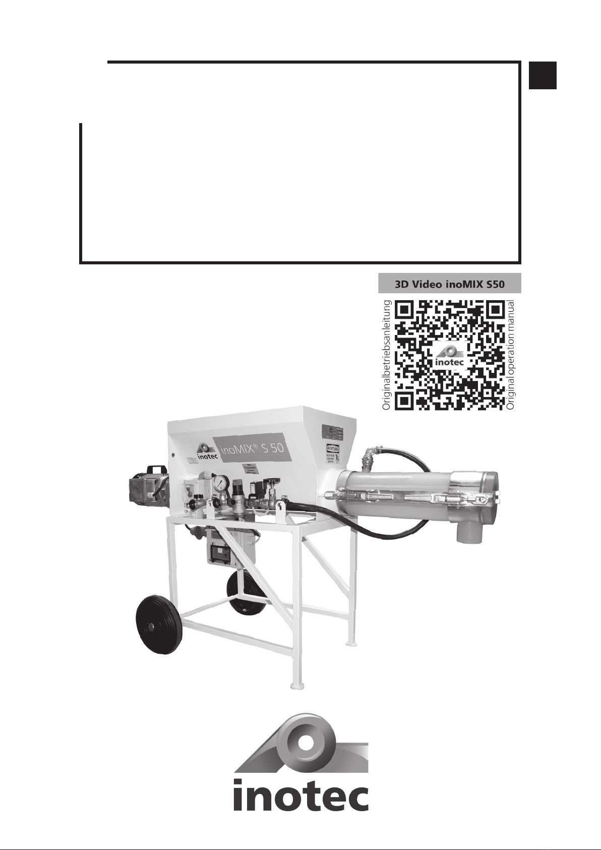
InoTec inoMIX S50 S Installation instructions
EN
Read this entire original operating manual before starting work.
Original Operating Manual
inoMIX S50 S continuous mixer

EN
Page 2
Thank you for trusting INOTEC. By purchasing you have opted for a quality product.
If you have any suggestions or any issues, we would be delighted to hear your suggestions for improvement
and your feedback. Speak to the sales representative assigned to you or, in urgent cases, contact us directly.
We work constantly to further develop our products and reserve the right to make changes for technical reasons
relating to building legislation.
Yours faithfully
INOTEC GmbH
Legal notice
Address: INOTEC GmbH
Daimlerstraße 9-11
79761 Waldshut-Tiengen
Germany
Tel: +49 (0)7741 6805 666
Fax: +49 (0)7741 6805 665
Internet: www.inotec-gmbh.com
Version as of: October 2023
Document number: 10044084-OBA-EN

Page 3
Inhalt
1 General information.................................................................................................................................. 5
1.1 Information about this manual ........................................................................................................................5
1.2 Symbol explanation ..........................................................................................................................................5
1.3 Information about this manual ........................................................................................................................5
1.3.1 Purpose of this operating manual...................................................................................................................................5
1.3.2 Disclaimer ......................................................................................................................................................................5
1.3.3 Warranty........................................................................................................................................................................5
1.3.3.1 Exercising claims .........................................................................................................................................................5
1.3.3.2 Warranty claims ..........................................................................................................................................................6
1.3.4 Carrying out repairs .......................................................................................................................................................6
2 Safety.......................................................................................................................................................... 6
2.1 Intended use ......................................................................................................................................................6
2.2 General risk sources...........................................................................................................................................6
2.2.1 Notices in the operating manual.....................................................................................................................................7
2.2.2 Performing checks before starting work .........................................................................................................................7
2.2.3 Conversions and changes...............................................................................................................................................7
2.2.4 Cleaning and maintaining the machine ..........................................................................................................................7
2.2.5 Changing the location of the machine ...........................................................................................................................7
2.3 Notices on the machine ....................................................................................................................................8
2.4 Personnel qualification......................................................................................................................................8
2.5 Responsibility of the operator..........................................................................................................................8
2.6 Personal protective equipment (PPE) ...............................................................................................................8
3 Technical data............................................................................................................................................. 9
3.1 Rating plate .......................................................................................................................................................9
3.2 Electric control system, pump output, particle size, weight, dimensions .....................................................9
3.3 Water measuring system...................................................................................................................................9
3.4 Material hopper .................................................................................................................................................9
3.5 Motor..................................................................................................................................................................9
3.6 Metering shaft ...................................................................................................................................................9
3.7 Mixing shaft .......................................................................................................................................................9
3.8 Noise emissions..................................................................................................................................................9
3.9 Operating conditions.........................................................................................................................................9
4 Assembly and function ........................................................................................................................... 10
4.1 Scope of delivery inoMIX S50 S (Art.-No. 10044084) ....................................................................................10
4.2 Functionality ....................................................................................................................................................10
4.3 Components .....................................................................................................................................................10
4.3.1 Description of the components ....................................................................................................................................10
4.3.1.1 Main frame with material hopper incl. metering shaft and wheels.............................................................................10
4.3.1.2 Switching cabinet .....................................................................................................................................................10
4.3.1.3 Water measuring system ...........................................................................................................................................10
4.3.1.4 Motor .......................................................................................................................................................................11
4.3.1.5 Mixing pipe and mixing shaft with mixing pipe cover ................................................................................................11
4.4 Displays and controls ......................................................................................................................................11
4.4.1 Water measuring system ..............................................................................................................................................11
4.4.2 Installing the water measuring system..........................................................................................................................11
4.4.3 Metering shaft ............................................................................................................................................................11
4.4.4 Mixing pipe and mixing shaft .......................................................................................................................................11
4.4.5 Motor ..........................................................................................................................................................................12
4.5 Connections......................................................................................................................................................12
4.5.1 Power connection (400 V) ...........................................................................................................................................12
4.5.2 Power connection of the motor and the ......................................................................................................................12
vibrating unit ........................................................................................................................................................................12
4.5.3 Water fitting connections.............................................................................................................................................13
4.6 Operating modes .............................................................................................................................................13
4.7 Accessories .......................................................................................................................................................14
4.8 Spare parts and diagrams ...............................................................................................................................15
4.8.1 Overview inoMIX S50 S................................................................................................................................................15
4.8.2 Water measuring system spare parts list .......................................................................................................................16
4.8.3 Metering shaft .............................................................................................................................................................17
4.8.4 Mixing pipe inoPOWERMIX “S” with mixing shaft and mixing pipe cover.....................................................................17
4.8.5 Mixing pipe cover for mixing pipe inoPOWERMIX “S”..................................................................................................18

EN
Page 4
4.8.6 Mixing shaft for mixing pipe inoPOWERMIX “S” ..........................................................................................................18
4.8.7 Drive unit.....................................................................................................................................................................19
5 Transport and storage ............................................................................................................................. 20
5.1 Safety instructions for transport ....................................................................................................................20
5.2 Transport inspection........................................................................................................................................20
5.3 Damage report.................................................................................................................................................20
5.4 Complaints .......................................................................................................................................................20
5.5 Packaging .........................................................................................................................................................20
5.6 Transporting the used machine in the vehicle...............................................................................................20
5.7 Storage .............................................................................................................................................................20
6 Installation ............................................................................................................................................... 21
6.1 Delivery condition of the machine .................................................................................................................21
6.2 Connecting the metering shaft and motor....................................................................................................21
6.3 Assembling the mixing pipe and mixing shaft..............................................................................................21
6.4 Connecting the electrical control system.......................................................................................................21
6.5 Installing the water measuring system..........................................................................................................22
7 Commissioning ....................................................................................................................................... 23
7.1 Opening and emptying bags of material.......................................................................................................23
7.2 Commissioning the inoMIX S50 S (processing bagged material).................................................................23
7.2.1 Function after commissioning (processing bagged goods) ............................................................................................23
7.3 Commissioning the inoMIX S50 S (processing material from a silo)............................................................24
7.3.1 Function after commissioning. (Processing material from a silo) ....................................................................................24
7.4 Changing the material.....................................................................................................................................24
7.6 Change of location on the construction site .................................................................................................24
8 Operation, use.......................................................................................................................................... 25
8.1 Checking operating behaviour .......................................................................................................................25
8.2 Checking the consistency of the material......................................................................................................25
8.3 Correcting flow fluctuations...........................................................................................................................25
8.4 Work break.......................................................................................................................................................25
8.5 End of work......................................................................................................................................................26
8.5.1 Switch off the machine (processing bagged goods) ......................................................................................................26
8.5.2 Switch off the machine (processing material from a silo)...............................................................................................26
8.5.3 Dismantling and cleaning the mixing pipe and mixing shaft..........................................................................................26
8.5.4 Dismantling the motor and metering shaft...................................................................................................................26
9 Cleaning & decommissioning ................................................................................................................. 27
9.1 Cleaning process ..............................................................................................................................................27
9.2 Decommissioning.............................................................................................................................................27
9.2.1 Empty and switch off the machine (processing bagged goods) .....................................................................................27
9.2.2 Empty and switch off the machine (processing material from a silo)..............................................................................27
9.2.3 Mixing pipe and mixing shaft with mixing pipe cover ...................................................................................................28
9.2.4 Water measuring system ..............................................................................................................................................28
9.2.5 Dismantling the motor and metering shaft...................................................................................................................28
10 Maintenance........................................................................................................................................... 28
10.1 Maintenance plan ..........................................................................................................................................28
10.2 Dirt trap sieve in the water inlet ..................................................................................................................29
10.3 Dirt trap sieve in the pressure reducing valve.............................................................................................29
10.4 Wear limit for metering shafts ....................................................................................................................29
10.5 Wear limit for mixing shafts ........................................................................................................................29
11 Faults, causes and solutions ................................................................................................................. 30
12 Dismantling and disposal ..................................................................................................................... 32
12.1 Safety..............................................................................................................................................................32
12.2 Dismantling ....................................................................................................................................................32
12.3 Disposal ..........................................................................................................................................................32
13 Systems................................................................................................................................................... 33
13.1 EC declaration of conformity ........................................................................................................................33
13.2 General Terms of Business of the company INOTEC GmbH........................................................................34
13.3 Circuit diagram for inoMIX S50 S ................................................................................................................35
14 Order form.............................................................................................................................................. 37
15 Index ....................................................................................................................................................... 38
16 Locations ................................................................................................................................................ 39
Page 5
EN
Chapter 1 General information
1 General information
1.1 Information about this manual
• This manual helps to ensure safe and efficient use of
the machine.
• Operating personnel must have carefully read through
and understood this manual before starting any work.
• Compliance with all the specified safety instructions is
a basic prerequisite for working safely.
• This manual is a component of the machine and must
be stored within direct proximity of the machine, acces-
sible to operating personnel at all times.
• In addition to the notices in these instructions, the local
accident prevention guidelines and national occupa-
tional health regulations also apply.
1.2 Symbol explanation
Hazard notices feature symbols to make them easier to
identify. These indicate the severity of the hazard.
• You must observe this information.
!
DANGER
DANGER indicates an immediate hazard.
Death or serious injuries may result from non-compliance.
!
WARNING
WARNING indicates a potentially dangerous
situation. Death or serious injuries may result from a failure
to avoid these situations.
!
CAUTION
CAUTION indicates a potentially dangerous
situation. Minor or slight injuries may result from failure to
avoid these situations or damage to the machine or some-
thing in its vicinity.
NOTE
NOTICE draws your attention to useful tips for
effectively handling the machine.
1.3 Information about this manual
1.3.1 Purpose of this operating manual
The operating manual is used to provide information to the
operating manager, assembly fitters and machine operators
on the construction site. It contains important instructions
for safe use, optimum results and a long service life.
!
DANGER
Risk of incorrect operation
Failure to observe the operating manual could put the
operator’s life and health at risk and damage the ma-
chine.
• Read this operating manual carefully before passing it
on to your assembly fitters or operators.
• Please ensure that assembly fitters and operators read
this operating manual carefully before they start install-
ing and commissioning the machine.
• Always keep the operating manual to hand and in a leg-
ible condition.
1.3.2 Disclaimer
All technical information, data and instructions for use con-
tained in this operating manual reflect the state of the art at
the time of printing and are based on our experience thus
far and the best of our knowledge.
The manufacturer cannot be held liable for any damages as
a result of:
• Failure to comply with this manual
• Improper use
• Assignment of non-trained personnel
• Unauthorised alterations
• Technical changes
• Use of non-approved spare parts
1.3.3 Warranty
Statutory warranty periods of 12 months from the date of
purchase/the date of invoice of the industrial end customer
apply to our machinery.
1.3.3.1 Exercising claims
In the event of a warranty claim, send the entire machine,
along with the invoice, to our headquarters in Waldshut-
Tiengen.
Contact our free INOTEC service hotline beforehand on
+49 7741 6805 777.
Page 6
EN
Chapter 2 Safety
1.3.3.2 Warranty claims
Claims apply only where material or manufacturing faults
exist and where machinery has been used properly. Wear
parts are not covered by the warranty. All claims shall be-
come void if third-party parts are installed, where the ma-
chinery has been improperly used or stored and in the event
of obvious non-compliance with the operating manual. In
this connection, we refer you to our General Terms of Busi-
ness.
1.3.4 Carrying out repairs
Repairs may only be carried out by employees at our
INOTEC service centres.
2 Safety
2.1 Intended use
You may only operate this machine if the following
conditions are met:
• The inoMIX S50 S is suitable for processing all factory-
premixed and machine-compatible dry mortars. Load
the continuous mixer only with dry goods (e.g. bagged
goods).
• Only use the machine within its limits of application
and according to the technical data.
• Pay particular attention to the safety and warning no-
tices outlined in this original operating manual.
!
DANGER
Improper use of the inoMIX S50 S may
result in danger to life and limb, as well as damage to
the inoMIX S50 S or other property.
!
WARNING
Danger due to misuse!
Misuse of the inoMIX S50 S can lead to hazardous
situations.
• Never use the inoMIX S50 S continuous mixer to produce
other products – such as food.
• Never use the inoMIX S50 S continuous mixer outside the
parameters specified in the “Technical data”.
2.2 General risk sources
!
DANGER
Electrical voltage.
Danger of death due to electric shock.
• Work on the electronic control system may only be per-
formed by a qualified electrician.
• Switch off the machine and pull out the mains plug.
• Secure the machine against unexpectedly being switched
back on.

Page 7
EN
Chapter 2 Safety
!
DANGER
Rotating shaft.
Danger of death due to being pulled into the ma-
chine and crushed.
When the motor is running, the metering shaft ro-
tates, even if the mixing pipe has been removed with
the mixing shaft!
• Do not reach into the rotating shaft.
• Do not place any objects into the rotating shaft.
1. Before working on the metering and mixing shaft, inter-
rupt the external power supply.
2. To do this, press the red pushbutton.
3. Pull out the mains plug.
4. Secure the machine against unexpectedly being switched
back on.
!
WARNING
Water jet.
Risk of injury and risk of property damage due to es-
caping water.
1. Interrupt the external water supply by closing the water
valve.
2. In order to release the pressure (approx. 2 bar), open the
water drainage valve on the water measuring system un-
der the pressure reducer.
3. Remove the hose from the external water supply.
4. Do not point the water jet at other people or yourself.
2.2.1 Notices in the operating manual
!
CAUTION
Safety notices in the operating manual
alert the operating personnel to any immediate
danger. Please observe all the technical and hazard
notices in this operating manual.
2.2.2 Performing checks before starting work
!
WARNING
Defects or damage can put the safety of
operating personnel at risk and impair the functional-
ity of the machine.
• Before commencing work, check the machine for any
obvious external damage or defects.
• Do not commission the machine if you notice any dam-
age to or defects in the machine.
• Ensure that the damage and/or defects are rectified.
2.2.3 Conversions and changes
!
DANGER
Conversions or changes can put the safe-
ty of operating staff at risk and impair the functional-
ity of the machine.
• Do not make any changes, additions or conver-
sions to the machine without first consulting
INOTEC GmbH and obtaining its written approval. Oth-
erwise, the operating license will become void.
2.2.4 Cleaning and maintaining the machine
!
WARNING
Cleaning and maintenance work can put
the safety of operating staff at risk and impair the
functionality of the machine.
1. Switch off the machine and pull out the mains plug.
2. Secure the machine against unexpectedly being
switched back on.
3. Before cleaning with the water jet, cover all the open-
ings that water must not penetrate into for safety and
functional reasons.
4. After cleaning, remove all the covers which were at-
tached to protect against the water.
2.2.5 Changing the location of the machine
!
CAUTION
Changing location can put the safety of
operating staff at risk and impair the functionality of
the machine.
1. Switch off the machine and pull out the mains plug.
2. Lift the machine up using the mixing pipe and place it
in a new location on the building site.
3. Always install the machine in such a way that it is level
and stable.
4. Secure the machine against undesirable movements.
5. Reconnect the machine to the external power supply
before restarting the machine.

Page 8
EN
Chapter 2 Safety
2.4 Personnel qualification
INOTEC offers training courses on operating the
inoMIX S50 S.
Use INOTEC service for the initial commissioning of the ma-
chine; this also serves as an opportunity to provide opera-
tors with training on how to operate the mixer.
!
DANGER
The unqualified operation of the
inoMIX S50 S may result in danger to the life and limb
of the operating personnel, as well as damage to the
inoMIX S50 S or other property.
2.5 Responsibility of the operator
• Only use trained or instructed personnel to operate the
inoMIX S50 S.
• Define employees’ responsibilities for operating, setting
up, maintaining and servicing the machine clearly.
• Only task untrained staff or individuals who have not re-
ceived any instruction with operating the machine when
there is a trained or instructed specialist available to su-
pervise them.
• Work on the electronic control system may only be per-
formed by a qualified electrician.
2.6 Personal protective equipment (PPE)
!
CAUTION
PPE – particularly gloves, safety boots, a
safety helmet and safety goggles and respiratory pro-
tection – must be used.
2.3 Notices on the machine
!
DANGER
Safety notices on the machine make oper-
ating staff aware of imminent danger.
The following warning labels are attached to the
inoMIX S50 S:
• WARNING. Do not reach into the machine (1).
• If there is a risk of frost, drain the water (2).
• The device may only be operated via a connector protect-
ed with an RCD (FI) IDh ≤ 30 mA (3).
• This QR code will take you to the original operating man-
ual, and a 3D animation of the assembly and the func-
tion of the mixer (4).
• Observe all the safety and hazard notices that are at-
tached to the machine.
• Always keep the safety and hazard notices in a clearly
legible condition.
Safety notice under
the rating plate
Safety notice above
the needle valve
2
1
QR code
on the
motor side
4
3
Page 9
EN
Chapter 3 Technical data
3 Technical data
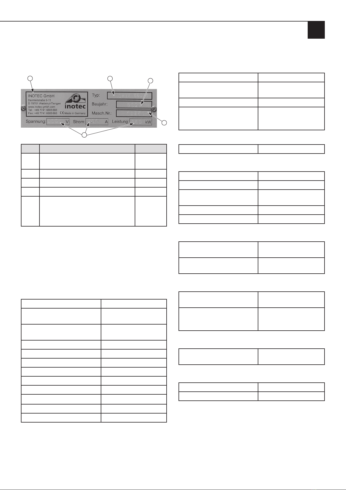
3.1 Rating plate
1
5
4
23
Item Component Value
1 Manufacturer, address and contact
details, CE marking
-
2 Name and type of machine -
3 Machine’s year of construction -
4 Machine number -
5Technical data
- Voltage
- Current
- Output
400 V
16 A
2.6 kW
You must always state the machine number if you would
like to order spare parts, have any queries or would like
to make a complaint. You will find this information on the
rating plate or on the delivery note.
3.2 Electric control system, pump output, particle size,
weight, dimensions
Mains voltage 400 V, 50 Hz
Mains supply line (CEE plug) 16 A (to be supplied by
customer)
Cross-section – Connecting
cable
5 x 2.5 mm2
Output 2.6 kW
Fuse 16 A
Mixing capacity max. 50 l/min.*
Weight approx. 83.5 kg
Dimensions:
Length without mixing pipe 1,200 mm
Length of mixing pipe 560 mm
Width 715 mm
Height 990 mm
* Material-dependent – observe the material manufacturer’s instructions.
3.3 Water measuring system
Pressure being too low From 2 to 6 bar
Pressure reducer
ex-works setting
2.0 bar
Solenoid valve 230 V, 50 Hz
Supply line ¾ inch water pipe
(to be supplied by cus-
tomer)
3.4 Material hopper
Fill quantity max. 75 l
3.5 Motor
Power/speed 2.6 kW, 386 rpm-1
Installation position Motor horizontal
Electrical data f = 50 Hz, I = 5.7 A,
U = 400 V, IP 55
Insulation class F, ED = S3 - 60 %
Colour unvarnished
3.6 Metering shaft
Maximum height of augur
blades:
18 mm
Minimum height of augur
blades:(wear limit)
12 mm
3.7 Mixing shaft
Maximum height of mixer
blades:
52 mm
Minimum height of mixer
blades
(wear limit)
44 mm
3.8 Noise emissions
Guaranteed sound power
level LWA
78 dB (A)
3.9 Operating conditions
Temperature range 2 - 45 °C
Relative humidity, maximum 80 %

Page 10
EN
Chapter 4 Assembly and function
4 Assembly and function
4.1 Scope of delivery inoMIX S50 S (Art.-No. 10044084)
The scope of delivery is generated using the components or-
dered and can be checked using the delivery note.
• Frame
• 2 running wheels
• Material hopper
• Gear motor
• PU mixing pipe
• Mixing shaft
• metering shaft
• Water fitting
• Operating manual
4.2 Functionality
The continuous mixer is filled with bagged goods as stan-
dard. The mixing and metering shafts are directly driven by
a gear motor. During operation, the dry material is con-
veyed from the material hopper into the mixing pipe via the
metering shaft. In the mixing pipe, the dry material − with
the addition of water − is mixed using the mixing shaft, to
form a homogeneous, paste-like product, and is conveyed
out of the mixing pipe.
NOTE
Note the optimum assembly sequence.
1. Push the metering shaft into the main frame.
2. Attach the motor to the material hopper by means of
the quick-release fastener, and ensure that the metering
shaft is connected to the motor via the motor bracket.
3. Insert the five-pin plug into the upper socket on the
switching cabinet. The socket below (4-pole) is the
power connection for the vibrating unit recommended
by INOTEC.
4. Assemble the mixing pipe by using both eccentric fas-
tenings on the main frame and push the mixing shaft
with the mixing pipe cover into the mixing pipe. En-
sure that the mixing shaft is connected to the metering
shaft.
5. Lock the two eccentric catches in the fixing bolts pro-
truding from the side of the mixing pipe cover.
6. Connect the main switch to the external power supply
(400 F / 16 A)
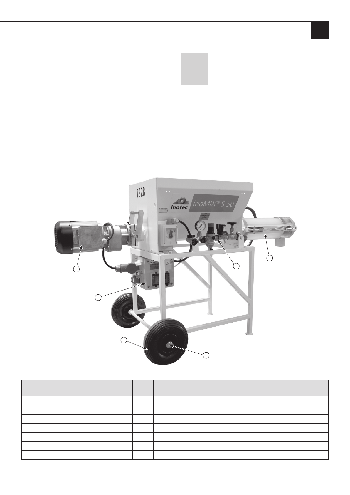
4.3 Components
435
1
2
4.3.1 Description of the components
Item Component
1 Main frame with material hopper
incl. metering shaft and wheels
2 Switching cabinet
3 Water measuring system
4 Motor
5Mixing pipe incl. mixing shaft with mixing pipe
cover
4.3.1.1 Main frame with material hopper incl. meter-
ing shaft and wheels
The switching cabinet with three sockets and the water mea-
suring system are mounted on the main frame. Push the me-
tering shaft into the main frame. The motor is attached to the
main frame by the quick-release fastener and the mixing pipe
by two eccentric fastenings. Finally, the mixing shaft with the
mixing pipe cover is pushed into the mixing pipe and locked to
the mixing pipe with two eccentric locks.
Material hopper with hopper mesh and toothed rail
4.3.1.2 Switching cabinet
The switching cabinet is attached to the main frame and
may only be opened by a qualified electrician. The residual
current circuit breaker is located under the Plexiglas cover
on the switching cabinet lid. The test button located there
must be pressed 1 x week.
4.3.1.3 Water measuring system
The water measuring system is attached to the main frame.
The optimum water quantity is set by opening and closing
the needle valve.
Page 11
EN
Chapter 4 Assembly and function
4.3.1.4 Motor
The motor is attached to the main frame by a quick-release
fastener. The CEE plug of the motor is connected to the top
socket on the side of the switching cabinet. The metering
shaft previously pushed into the main frame is connected to
the motor bracket attached to the motor.
4.3.1.5 Mixing pipe and mixing shaft with mixing pipe
cover
Assemble the mixing pipe by using both eccentric fastenings
on the main frame and push the mixing shaft with the mix-
ing pipe cover into the mixing pipe. Ensure that the mixing
shaft is connected to the metering shaft. Lock the two ec-
centric locks in the fixing bolts protruding from the side of
the mixing pipe cover.
4.4 Displays and controls
Main switch, switching cabinet and water measuring
system. The red rotary switch on the main switch has only
one off and one on position, clearly marked 0 and 1.
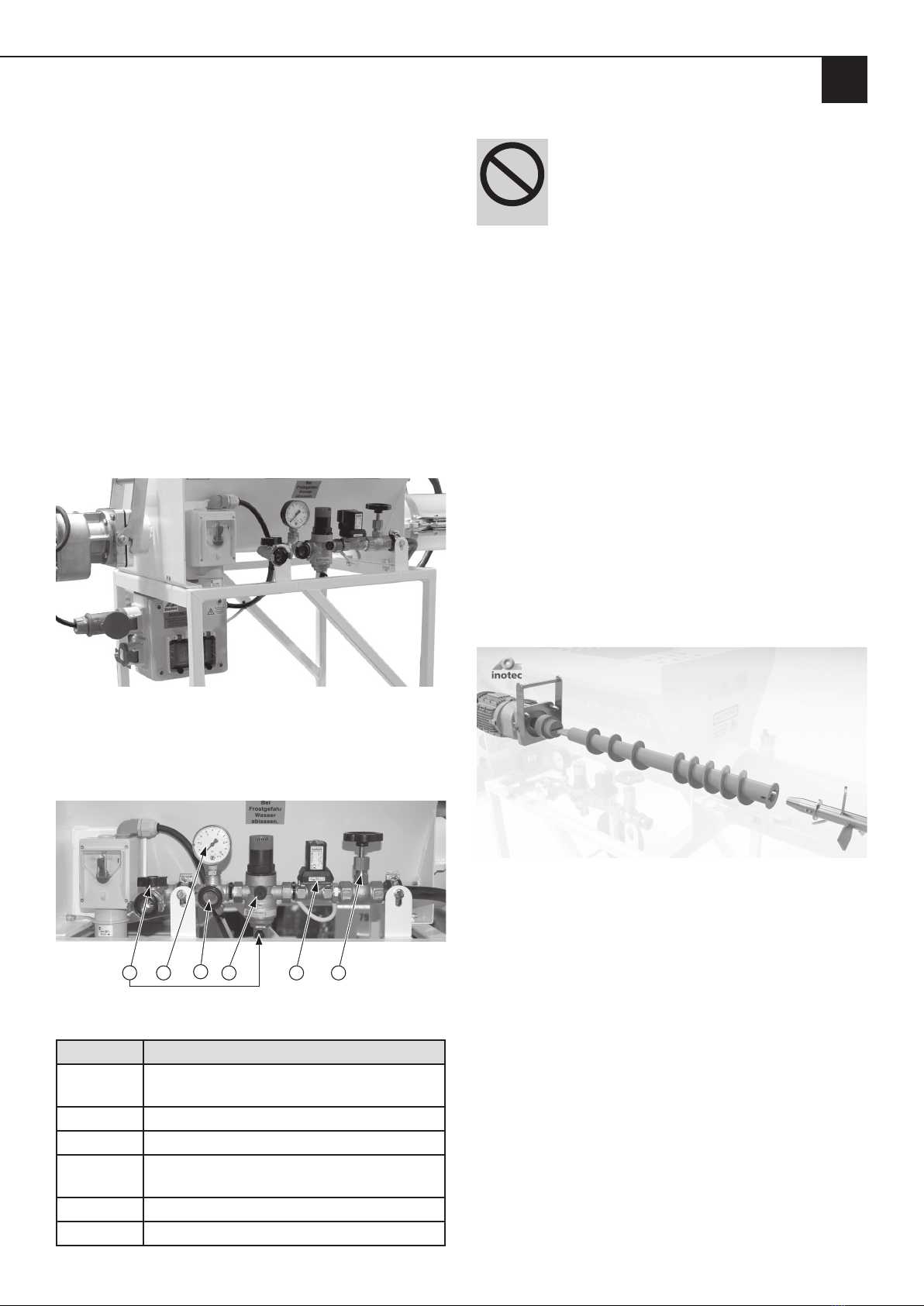
4.4.1 Water measuring system
134 56 2
Description of the components in the diagram
Item Component
1Water drainage taps and connection for the
external cleaning hose
2 Needle valve
3 Pressure reducer
4 GEKA coupling with sieve insert
(external water connection)
5 Solenoid valve
6 Pressure gauge
WARNING
Water jet.
Risk of injury and risk of property damage due to
escaping water.
• Do not point the water jet at other people or yourself.
4.4.2 Installing the water measuring system
1. Connect the supply hose to the external water supply.
2. Open the water valve until a steady water jet comes out
of the hose in order to both clean the water hose of dirt
and ventilate it.
3. Then close the valve on the external water supply.
4. Connect the external water hose to the GEKA
coupling of the water fitting below the pressure gauge.
5. Close the two water drainage taps on the water fitting.
6. Connect the internal water hose to the mixing pipe.
4.4.3 Metering shaft
The metering shaft is connected to the motor via motor
bracket and rotates during operation in the main frame.
The mixing shaft is also connected to the metering shaft via
a plug-in connection. The metering shaft can be pulled out
for cleaning and maintenance work.
This sectional image illustrates the connection from the
motor to the metering shaft, and from the metering shaft
to the mixing shaft.
4.4.4 Mixing pipe and mixing shaft
The mixing shaft is firmly screwed to the mixing pipe cover.
The mixing shaft is connected to the metering shaft via a
plug-in connection. The mixing shaft in the mixing pipe
rotates during operation. It is protected from tampering
by the mixing pipe cover. The mixing shaft alongside the
mixing pipe cover can be pulled out of the mixing pipe for
cleaning and maintenance work.

Page 12
EN
Chapter 4 Assembly and function
!
DANGER
Rotating shaft.
Danger of death due to being pulled into the ma-
chine and crushed.
When the motor is running, the metering shaft ro-
tates, even if the mixing pipe has been removed with
the mixing shaft!
• Do not reach into the rotating shaft.
• Do not place any objects into the rotating shaft.
1. Before working on the metering and mixing shaft, inter-
rupt the external power supply.
2. To do this, press the red pushbutton.
3. Pull out the mains plug.
4. Secure the machine against unexpectedly being switched
back on.
4.4.5 Motor
!
DANGER
Electrical voltage
Danger of death due to electric shock.
1. Work on the electronic control system may only be per-
formed by a qualified electrician.
2. Switch the machine off. To do this, press the red push-
button.
3. Pull out the mains plug.
4. Secure the machine against unexpectedly being switched
back on.
4.5 Connections
4.5.1 Power connection (400 V)
Power connection at the main switch (400 V / 16 A)
4.5.2 Power connection of the motor and the
vibrating unit
12
The 5-pin CEE plug of the motor (1) is plugged into the
upper socket. Below this is the 4-pin junction box for an
optional vibrating unit that is attached to the silo.

Page 13
EN
Chapter 4 Assembly and function
4.5.3 Water fitting connections
1 2 3
Connection for a water hose for cleaning the mixing pipe
and mixing shaft (1), connection of the external water
supply (2), connection of the mixing pipe to the water
supply (3).
4.6 Operating modes
The ready-mixed material can be filled into any container
(bucket, wheelbarrow, etc.), or you can combine the ino-
MIX S50 S e.g. with the 400 V feed pump inoBEAM F50.
The inoMIX S50 can also be connected directly to a silo with
an optional transition hood (1) (Art. No. 10044126), which
is attached to the material hopper with four eyebolts and a
flexible rubber transfer bellows (2) with a flange (DN 250).
12
Page 14
EN
Chapter 4 Assembly and function
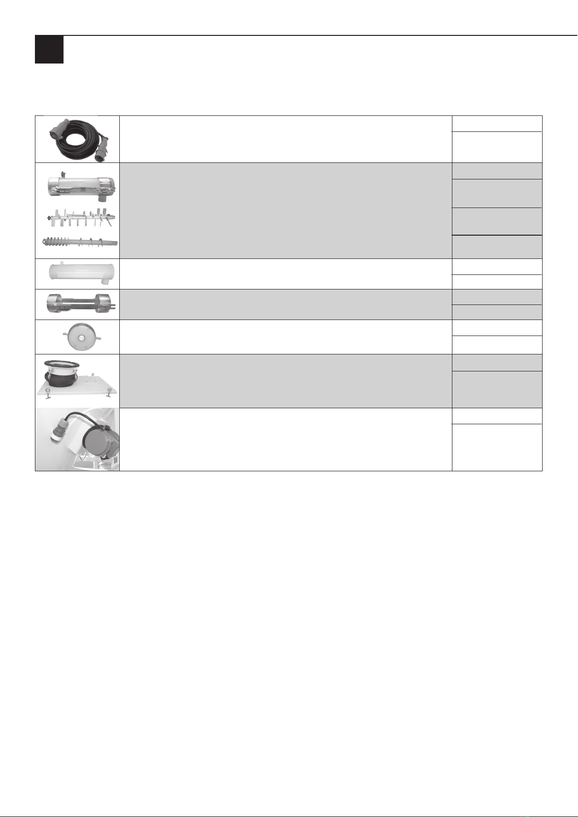
4.7 Accessories
The following accessories can be supplied for the inoMIX S50 S.
400 V extension cable, 5 x 2.5 mm², length 20 m, CEE plug and coupling Item no.
10015199
PU mixing pipe inoPOWERMIX “S”
Including mixing shaft, mixing pipe cover and holders
Mixing shaft for inoPOWERMIX “S” for adhesive and reinforcement mortar
Dosing shaft for inoMIX S50 “S
Pitch 30 mm, e.g. for adhesive and reinforcing mortar
Item no.
10044030
10040026
10043255
PU inlay for mixing pipe inoPOWERMIX “S Item no.
10044013
Steel frame complete for inoPOWERMIX “S” mixing pipe Item no.
10044012
Mixing pipe cover for inoPOWERMIX “S”
incl. Plastic displacement for the mixing shaft.
Item no.
10044102
Optional transition hood with a flexible rubber transfer bellows and with a flange
(DN 250). The transition hood is attached to the material container of the inoMIX S50 S
with four eyebolts.
This allows the inoMIX S50 S to be connected directly to a silo.
Item no.
10044126
Electric vibration motor (three-phase unbalance motor) as external vibrating unit for
attachment to silos to prevent material flow and compaction problems.
Mains voltage: 400 V / 50 Hz
Item no.
10043960
Page 15
EN
Chapter 4 Assembly and function
4.8 Spare parts and diagrams
The spare parts for the inoMIX S50 S are marked with num-
bers in the following images. The individual items are de-
scribed in the table under the respective diagrams.
Description of the table columns:
Item: Corresponds to the number in the drawing,
with which a spare part is marked.
Item no.: INOTEC Article Number.
Installation
quantity: Number of parts of this item as installed in
the original inoMIX S50 S.
UQ: Unit of measure of this item.
Name: Designation of the spare part.
NOTE
Use the order form at the end of this
operating manual to order spare parts.
4.8.1 Overview inoMIX S50 S
4
1
6
5
2
3
Item Item no. Installation
quantity
UQ Name
10044084 1 Units inoMIX S50 S continuous mixer 2.6 kW 400/50Hz
1 10044088 1 Units Control box inoMIX S50 S complete
2 10042609 2 Units Wheel (puncture-free)
3 10006192 2 Units Starlock cap, d = 20 mm
4 10044083 1 Units Drive unit 2.6 kW for inoMIX S50 S
5 10044030 1 Units Mixing pipe inoPOWERMIX “S
6 10043267 1 Units Water measuring system

Page 16
EN
Chapter 4 Assembly and function
4.8.2 Water measuring system spare parts list
14
7
5
17
4 1
10
12
6
8
9
8
15
13
10
12
11
3
16 2
Item Item no. Installation
quantity
UQ Name
1 10006459 1 Units Needle valve, ¾“ IT
2 10023112 1 Units Solenoid valve 1/2”, 230 V, type 6213A
3 10006477 1 Units Reduction nipple, 3/4” / 1/2” ET
4 10006465 1 Units Pressure reducer D06F-1/2, with brass
4.1 10006464 1 Units Brass sieve cup
4.2 10006518 1 Units Replacement strainer for pressure reducer
5 10006466 1 Units Pressure gauge, 0 - 10 bar, 1/4” below
6 10017912 1 Units Mini ball valve, 1/4”, IT + ET
7 10022412 1 Units Ball valve, 12”, with butterfly handle, IT/IT
8 10022372 3 Units GEKA coupling, 1/2” IT
9 10006007 1 Units Brass sieve insert
10 10006470 2 Units Hose nozzle, 1/2” ET x 13 mm nozzle
11 10021968 1.0 Meter Rubber water hose, 1/2”
12 10022443 2 Units Hose clamp, 1-ear, 19.2 - 21.8, (1/2”)
13 10006471 1 Units Angular, 1/2” 90°, galvanised IT
14 10006472 1 Units Pipe double nipple, 1/2” x 60 mm, galvanised
15 10006497 1 Units Angular, 1/2” IT + ET
16 10006478 1 Units Reduction nipple, 1/2” ET x 1/4” IT
17 10006479 1 Units T-distributor, 1/2”, galvanised, no. 223
- 10006473 1 Units Reduction nipple
- 10004302 1 Units PE seal

Page 17
EN
Chapter 4 Assembly and function
4.8.3 Metering shaft
Metering shaft
30 mm gradient Item no. 10043255 (e.g. bonding and reinforcing compounds)
4.8.4 Mixing pipe inoPOWERMIX “S” with mixing shaft and mixing pipe cover
5
4
17
3
2
6
8
Mixing pipe
Item Item no. Installation
quantity
UQ Name
1 10044030 1 Units Mixing pipe inoPOWERMIX “S” with mixing shaft, cover and with
eccentric locks
2 10017068 4 Units Eccentric lock, size 0
3 10022457 1 Units Hose clamp, 3/4”
4 10022379 1 Units GEKA coupling, 3/4”, nozzle
5 10044012 1 Units Steel frame complete for mixing pipe inoPOWERMIX “S”
6 10044013 1 Units PU inlay for mixing pipe inoPOWERMIX “S”
7 10040026 1 Units Mixing shaft for mixing pipe
8 10044102 1 Units Mixing pipe cover for inoPOWERMIX “S”
inc. Plastic displacement for the mixing shaft

Page 18
EN
Chapter 4 Assembly and function
4.8.5 Mixing pipe cover for mixing pipe inoPOWERMIX “S”
12
Mixing pipe cover for inoPOWERMIX “S” Mixing pipe
Item Item no. Installation
quantity
UQ Name
1 10044008 1 Units Mixing pipe cover for mixing pipe inoPOWERMIX “S”
2 10006175 1 Units Plastic transfer for the mixing shaft
4.8.6 Mixing shaft for mixing pipe inoPOWERMIX “S”
1
2
3
Mixing shaft
Item Item no. Installation
quantity
UQ Name
1 10040026 1 Units Mixing shaft for mixing pipe inoPOWERMIX “S”
for adhesive and reinforcing mortar
2 10040694 1 Units Allen screw, 8 x 12 mm, left-hand thread
3 10040419 1 Units Splash guard washer

Page 19
EN
Chapter 5 Transport and storage
4.8.7 Drive unit
1
3
2
5
11
78
6
10
9
Motor
Item Item no. Installation
quantity
UQ Name
- 10044083 1 Units Complete drive unit
1 10044080 1 Units Spur gear motor, 2.6 kW, 400 V
2 10043829 1 Units Complete motor flange (incl. items 6, 7, 8 and 9)
- 10039955 1 Units Motor flange without attachments
3 10015262 1 Units CEE plug 5 x 16 A
4 10043256 1 Units Motor shaft
4.1 10039933 1 Units Radial shaft seal
5 10016644 1 Units Bow handle
6 10039944 2 Units Centring bolt
7 10039945 2 Units Eccentric bushes
8 10039954 1 Units Clamping lever for quick-release fastener
9 10041184 1 Units Motor flange seal
10 10008105-003 1 Meter Rubber cable 4 x 1.52H07RN-F
11 10043980 1 Units Cover for quick release flange
NOTE
Use the order form at the end of this operating manual to order spare parts.

Page 20
EN
Chapter 5 Transport and storage
5 Transport and storage
5.1 Safety instructions for transport
!
DANGER
Slipping machine
Danger of death for drivers and transport users.
• Ensure that the machine is in a secure position during
transport.
• Secure the machine against slipping.
!
WARNING
Risk of injury posed by carrying or lifting
machine
• The machine weighs over 80 kg. To prevent overload-
ing and damaging the spine, at least 3 people must lift
or carry the machine.
5.2 Transport inspection
NOTE
Check the machine to ensure that
all components are present and for trans-
port damage immediately upon receipt.
• Do not leave any parts in the packaging.
5.3 Damage report
Proceed as follows in the event of externally visible
transport damage:
1. Write a damage report with the following details:
- Your client address
- Name of the transport company and the driver
- Date and time of the delivery
- Order number and machine name
according to the delivery note
- Description of the damage
- Signature of the driver
- Signature of the recipient at the customer’s premises
2. Have the transport damage confirmed by means of the
driver’s signature.
3. Send one copy of the damage report to
the transport company and another to
Inotec GmbH.
4. And clarify the possible ways in which the damage
could be remedied with one of our service centres (see
second last page)
5.4 Complaints
Claims for compensation relating to transport damage can
only be made if the delivery company is informed of the
same without undue delay.
5.5 Packaging
The new machine will be shipped cellophane-wrapped on
a Euro pallet.
• Dispose of the packaging material as required by law.
5.6 Transporting the used machine in the vehicle
!
DANGER
Slipping machine.
Danger of death for drivers and transport users.
1. Ensure that the machine is stored securely during trans-
port.
2. Secure the machine against slipping.
NOTE
Leaking material residue
• Clean the machine before transport.
• Secure the machine in the vehicle using suitable fixing
materials.
5.7 Storage
If the machine is not likely to be used for an extended
period of time, thorough cleaning will be required.
Store the machine under the following environmental
conditions:
• Dry
• Frost-free
• Protected from dust
• Protected against corrosion (e.g. salt water)
Table of contents
Popular Kitchen Appliance manuals by other brands


Clas Ohlson
Clas Ohlson SBL-811-UK manual

Salton
Salton HB-1094 Instruction booklet

Blodgett
Blodgett SC-GH Series Installation operation & maintenance

Johnson
Johnson Poker Instructions for use

Sienna
Sienna SureCare SGS-0308 instruction manual

Ninja
Ninja Foodi NeverDull Essential Knife System quick start guide


