InoTec INOLux LED User manual

INOLux LED Art. Nr. 820 030
INOLux LED Art. no. 820 030
Lieferumfang
Bitte prüfen Sie, ob Sie alle nachfolgend aufgeführten Teile erhalten haben:
• Leuchte
• Ladestation
• Netzkabel 1,5 m für Anschluss an 230 V AC Versorgung
• Anschlusskabel 1,9 m für Anschluss an 12 V/24 V DC KFZ-Bordnetz mit An-
schlussstecker für Bordnetzsteckdose
• Farbscheibe, orange
• Bedienungsanleitung
Scope of supply
Please check whether you received the components listed below:
• Lamp
• Charging station
• Power cord 1.5 m for connection to 230 V AC supply
• Supply cable 1.9 m for connection to 12 V/24 V DC vehicle power system with
connecting plug
• Colour screen, orange
• Operating instructions
Allgemeine Hinweise
•
Nach dem Auspacken des Gerätes nehmen Sie bitte eine Überprüfung auf Voll-
ständigkeit und erkennbare äußere Beschädigungen vor. Melden Sie oensicht-
liche Beschädigungen sofort, da wir spätere Reklamationen nicht anerkennen.
•
Die Hinweise der Montage- und Betriebsanleitung sind vor der ersten Inbe-
triebnahme zu beachten!
•
Im Zuge der Produktverbesserung behalten wir uns technische Änderungen
vor.
•
Bei fehlerhafter Installation bzw. Eingri in das Gerät erlischt der Garantiean-
spruch!
•
Für Schäden, die auf Grund der Nichtbeachtung dieser Montage- / Betriebsan-
leitung entstehen, übernehmen wir keine Haftung.
• Generell sind nur Originalersatzteile zu verwenden!
Important notes
•
After unpacking kindly check for complete delivery and any visible external
damages. Furthermore, inform the forwarding agent about visible damages at
once, as we do not accept complaints that reach us at a later time.
•
Prior to starting the system take into consideration all references in the moun-
ting and operating instructions!
•
In the interest of product improvment we reserve the right to make technical
changes to the appliance.
•
All guarantee claims cease in case of wrong installation or of any intervention
on the products.
• We do not take any liability for damages or injuries arising from failure to follow
instructions relating to product’s use
• In general original spare part must be used.
Module, Leuchten, Verpackungsmaterialien und Batterien sind gemäß
den Bestimmungen zu entsorgen!
Modules, luminaires, packing materials and batteries have to be
disposed as per national requirements!
Bedienungsanleitung
Operating Instructions
Hinweise
Notes
Hinweise Montage / Mounting Funktion / Function
Notes
708 210 A 07/2015
Arbeits- und Handnotleuchte INOLux LED Set
Work and Emergency hand lamp INOLux LED Set
Anwendungsbereich
Einsatz als Arbeits- und Handnotleuchte. Sie darf in einem Temperaturbereich
von -20 °C bis +40 °C eingesetzt werden.
Application range
This work and emergency hand lamp may be employed in a temperature
range of -20 °C to +40 °C.
Technische Daten
Spannungsversorgung, Netzteil: 230 V AC 30mA
Spannungsversorgung, mobil: 12 V/24 V DC 300mA /150mA direkter
Anschluss an Autobatterie
Ladedauer: 15 Stunden
48 Stunden vor Erstinbetriebnahme
Betriebstemperatur: -20 bis +40 °C
Gehäusematerial: Polyamid PA 12
Power LED: Leuchtdauer: 5 Stunden
Akkumulator: Blei-Gel, 4 V; 3,5 Ah, wartungsfrei
Schutzart : Leuchte:
Ladestation:
Laserklasse 1
Zubehör auf Anfrage lieferbar
Technical data
Electric power supply: 230 V AC
Electric power supply, portable: 12 V/24 V DC Direct connection to car
battery
Charging time: 15 hours
48 hours before first operation
Operating temperature: -20 bis +40 °C
Casing material: Polyamid PA 12
Power LED: Burn time: 5 hours
Rechargeable battery: Lead gel, 4 V; 3,5 Ah, maintenance-free
Enclosure type: Lamp :
Charging station:
Laser class 1
Accessories available on request
Ersatzteile
Zum Austausch von Dichtungsring und Akkumulator ausschließlich Original
INOLux-Ersatzteile verwenden. Nur Originalteile gewährleisten ordnungsgemä-
ße Funktion und Sicherheit!
INOLux Ladestation Art. Nr. 820 031
INOLux Vorsatzscheibe klar Art. Nr. 820 032
INOLux Vorsatzscheibe rot Art. Nr. 820 033
INOLux Vorsatzscheibe grün Art. Nr. 820 034
INOLux Vorsatzscheibe orange Art. Nr. 820 035
INOLux LED Not- Handleuchte o. Zubehör Art. Nr. 820 036
INOLux Ersatzbatterie 4V 3,5Ah Art. Nr. 890 105
Spare parts
For replacement of seal rings and rechargeable batteries use original AccuLux
spare parts only. Only original spares en-sure proper function and safety!
INOLux Charging station Art. no. 820 031
INOLux Colour screen clear Art. no. 820 032
INOLux Colour screen red Art. no. 820 033
INOLux Colour screen green Art. no. 820 034
INOLux Colour screen orange Art. no. 820 035
INOLux LED Emergency hand lamp without accessories Art. no. 820 036
INOLux Battery 4V 3,5Ah Art. no. 890 105
Maß /Dimension:
Dimension:
Bohrbild für Befestigung der Ladestation
Drilling template for installation of the charging station
192
246
103
120
INOTEC
Sicherheitstechnik GmbH
Am Buschgarten 17
D - 59 469 Ense
Telefon +49 29 38/ 97 30 - 0
Telefax +49 29 38/ 97 30 - 29
e-mail info@inotec-licht.de
www.inotec-licht.de
INOTEC
Sicherheitstechnik GmbH
Am Buschgarten 17
D - 59 469 Ense
Telefon +49 29 38/ 97 30 - 0
Telefax +49 29 38/ 97 30 - 29
e-mail info@inotec-licht.de
www.inotec-licht.de
112 , 6
124
12, 8
36,338
12, 8
110 , 8
85
Automatische Funktionen Not-
lichtfunktion:
Wenn die Spannungsversorgung
der Ladestation ausfällt, schaltet die
Haupt-LED der Handnotleuchte ein.
Sie bleibt eingeschaltet, bis die Span-
nung wieder anliegt. Bei Entnahme
der Leuchte aus der Ladestation
bleibt sie eingeschaltet, bis sie manu-
ell ausgeschaltet wird.
Funktionskontrolle der Haupt-
LED:
Die Haupt-LED leuchtet kurz auf und
erlischt wieder, wenn die Leuchte aus
der Ladestation genommen wird.
Danach erfolgt die
Funktionskontrolle der Pilot-LED:
Die Pilot-LED leuchtet kurz auf und
erlischt wieder.
Schutz vor Tiefentladung des
Akkumulators:
Bei mangelnder Spannung schaltet
die Leuchte von der Haupt- auf die
Pilot-LED um. Leuchte umgehend
laden!
Information zum Fahrzeugeinbau
Die Ladestation ist nach Anhang I,
3.2.9 RL 2006/28/EG geprüft und für
den Einbau in KfZ approbiert.
Wenn das KfZ die Möglichkeit
vorsieht, von außen über Stecker mit
230V AC zu laden, sind sowohl 230V
AC als auch 12/24 V DC anzuschlie-
ßen, da sonst beim Trennen der
230V-Versorgung von außen die
Leuchte in die automatiche Notlicht-
funktion übergehen und sich dabei
entladen würde.
Wenn die 230 V-Versorgung getrennt
wird, übernimmt die Fahrzeug-
batterie die Ladefunktion bis zum
Unterschreiten der unten genannten
Grenzwerte und bricht dann den
Ladevorgang ab, um eine Tiefent-
ladung der Fahrzeugbatterie zu
vermeiden.
Grenzwerte:
Bei 12 V DC Nennspannung 11,8 V
Bei 24 V DC Nennspannung 23,6 V
Automatic functions Emergen-
cy hand lamp function:
If the electric power supply of the
charging station fails, the main
LED switches to the emergency
hand lamp. It remains switched
on, until the voltage supply
returns. When removed from
the charging station, the lamp
remains switched on until it is
switched off manually.
Function control for the main
LED:
The main LED briefly switches on
and back off when the lamp is re-
moved from the charging station.
Then it runs the
Function control for pilot LED:
The pilot LED briefly switches on
and then back off.
Protection of the rechargeable
battery from total discharge:
When the voltage is dropping,
the lamp switches over from main
LED to pilot LED. Recharge the
lamp as soon as possible!
Information for installation in
a vehicle
The charging station is tested
according to appendix I, 3.2.9 of
directive 2006/28/EC and appro-
ved for installation in vehicles.
If the vehicle provides the possi-
bility to load via plug at 230 V AC,
you should connect the lamp to
230 V AC as well as 12/24 V DC,
since external disconnection of
the 230 V-supply would otherwi-
se switch the lamp to automatic
emergency function and thereby
deplete its battery.
When the 230 V-supply is discon-
nected, the vehicle battery takes
over the charging function until
its voltage drops below the limit
values listed below; it then stops
charging to avoid total discharge
of the vehicle battery.
Limit values:
At 12 V DC nominal voltage 11.8 V
At 24 V DC nominal voltage 23.6 V
Akkumulator tauschen Replacing battery Betrieb Operation
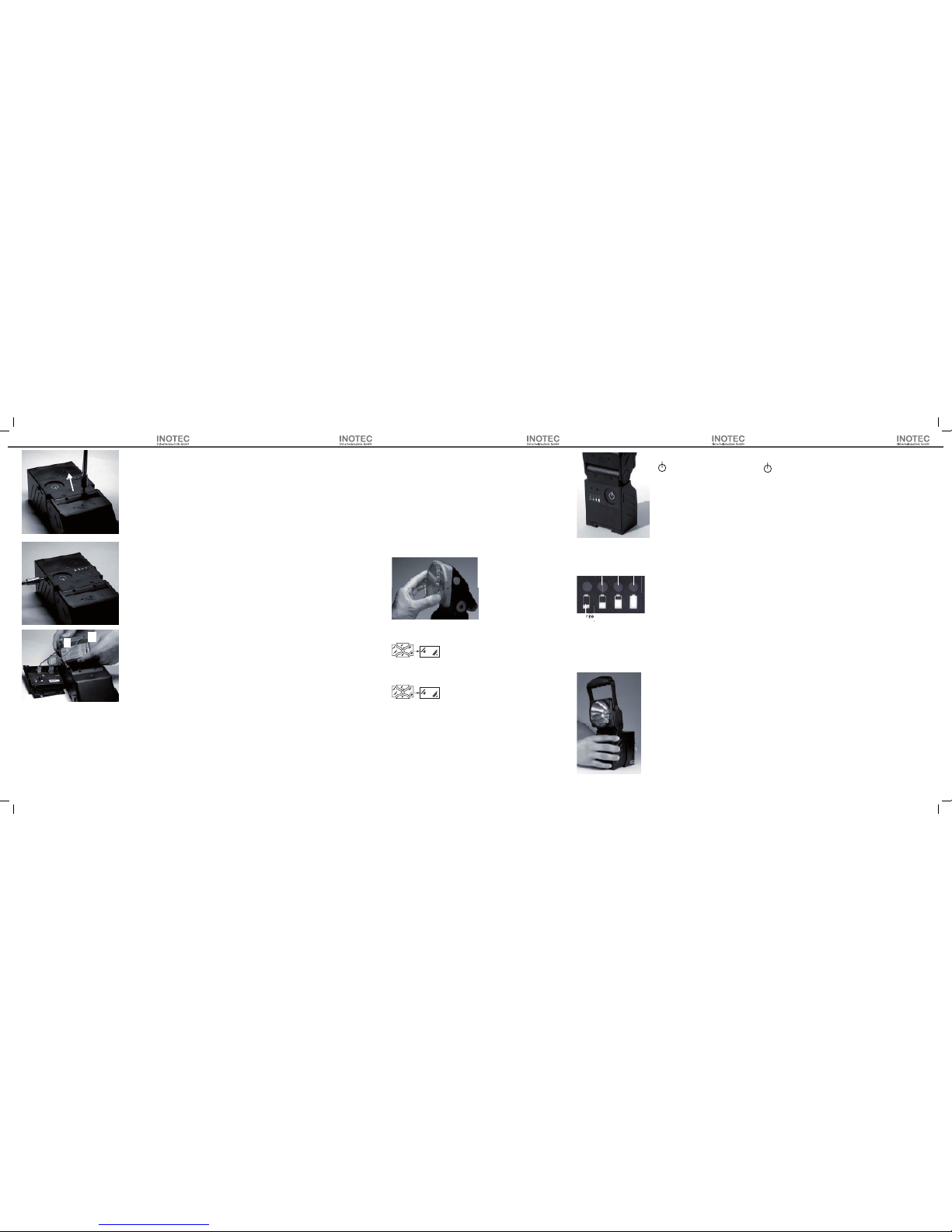
Akkumulator austauschen
Das Hinweisschild mit dem
zulässigen Akkutyp ist auf
dem Akku vermerkt.
Akku wie folgt wechseln:
• Die Arbeits- und Handnot-
leuchte vom Ladegerät tren-
nen und ausschalten (Aus).
• Die Rückwand der Ar-
beits- und Handnotleuchte
entfernen, indem Sie die vier
Schrauben an der Rücksei-
te und die zwei seitlichen
Schrauben lösen. (1, 2)
•Den Akku aus den Führungs-
schienen nach vorne ziehen.
Achtung: Vermeiden Sie
Kurzschluss!
•Die schwarze Steckvebin-
dung (-) und die rote Steck-
verbindung (+) vom Akku
lösen. (3)
• Den neuen Akku in die Füh-
rungsschienen einsetzen.
• Die schwarze Steckverbin-
dung (-) und die rote Steck-
verbindung (+) polrichtig am
Akku anschließen. (3)
• Die Arbeits- und Handnot-
leuchte in umgekehrter Rei-
henfolge wieder verschlie-
ßen.
• Sicherstellen, dass alle sechs
Schrauben an der Rückwand
angezogen sind. Die beiden
längeren Schrauben seitlich
einschrauben. (1, 2)
Replacing the rechargeable battery
• Disconnect the lamp from the charging
station and shut it off.
• Remove the rear panel of the work and
emergency lamp by loosening the four
screws on the rear and the two screws on
the sides. (1, 2)
• Pull the rechargeable battery forward
from the seating rails.
Warning: Avoid shorting the connections!
• Remove the black connector (-) and the
red connector (+) from the rechargeable
battery. (3)
• Insert the new rechargeable battery into
the seating rails.
• Connect the black plug-type connector (-)
and the red plug-type connector (+) cor-
rectly polarised to rechargeable battery.
(3)
• Close the work and emergency lamp in
reverse sequence.
• Be sure that all six screws in the rear panel
are fastened. Screw the two longer screws
in on the sides. (1, 2)• Close the work and
emergency hand lamp in reverse se-
quence.
2.
3. - +
Reinigung
Die Leuchte, Farbscheiben und Ladestation ausschließlich mit einem
feuchten Tuch reinigen, um elektrostatische Aufladung zu vermeiden.
Das Gelenk des Leuchtenkopfes kann mit einem Schraubendreher
nachgestellt werden.
Cleaning
The lamp, colour screens and charging station must be cleaned exclusi-
vely with a wet cloth to avoid electrostatic charge.
The hinge of the lamp head may be adjusted with a screwdriver.
Betrieb
1 Mal = Haupt-LED ein
2 Mal = Haupt-LED blinkt
3 Mal = Pilot-LED ein
4 Mal = Aus
Die Kapazitätsanzeige wird in jedem
Schalt-zustand (nicht bei Aus) ange-
zeigt.
Akku laden
Die Ladestation ist geeignet für den
Anschluss an:
• 230 V AC Netzspannung
• 12 V DC KfZ-Bordnetz
• 24 V DC KfZ Bordnetz
Zur Befestigung siehe Maßbilder.
Akkumulator laden, wenn nur die
rote LED der Ladeanzeige leuchtet.
Während der Ladung leuchtet die
Pilot-LED mit reduzierter Helligkeit.
Wenn der Akkumulator vollgeladen
ist, erlischt die Pilot-LED. Die Lade-
dauer beträgt ca. 15 Stunden.
Zum Laden an einer Fahrzeugbatte-
rie mit 12 V sind mindestens 11,8 V,
bei 24 V Batterien 23,6 V notwendig.
Wenn diese Werte unterschritten
werden, bricht das Gerät den Lade-
vorgang ab, um eine Tiefentladung
der Spannungsquelle (Fahrzeugbat-
terie) zu vermeiden.
Die Leuchte muss in der Ladestation
einrasten.
Die Leuchte in der Ladestation las-
sen, solange sie nicht benutzt wird.
Operation
1-time = main LED on
2-times = main LED blinking
3-times = pilot LED on
4-times = off
The capacity is indicated in any swit-
ching status (not if off).
Charging the rechargeable battery
The charging station may be connec-
ted to:
• 230 V AC line voltage
• 12 V DC vehicle power system
• 24 V DC vehicle power system
For fixing see dimension diagramm.
Charge the rechargeable battery
when only the red LED of the capa-
city indicator is on. While charging,
the pilot LED lights up with reduced
intensity. The pilot LED shuts off
when the rechargeable battery is
fully charged. The charging time is
approx. 15 hours.
For loading at a vehicle battery with
12 V you need at least 11.8 V, at a
24 V battery at least 23.6 V. If these
standard values are not reached,
the unit stops charging to avoid a
total discharge of the voltage supply
source (vehicle battery).
The lamp must latch into the char-
ging station.
Leave the lamp in the charging stati-
on until utilisation.
Nur rot - laden !
red only - Charge!
grün / green
50% 75% 100%
Einsetzen in die Ladestation
Inserting the lamp into the charging station
Shattered covers have to be replaced!
Jede zersprungene Schutzabdeckung ist zu ersetzen!
Farbscheibe einsetzen
Die Farbscheibe in die seitlichen Bolzen am Leuchtenkopf einsetzen
und fest drücken, bis sie einrastet.
Inserting the colour screen
Insert the colour screen into the lateral pins at the lamp head and press
it firmly until it latches.
1.
Nur rot - laden !
red only - Charge!
This manual suits for next models
1


