Inoxtrend Pastry & Gastronomy 610 User manual
FORNI A CONVEZIONE - VAPORE
ISTRUZIONI PER L’INSTALLAZIONE
ITALIANO
605 / 610
Mod. Analogic
IT
Pastry & Bakery Electromecanic 5-10 x (60x40)
2
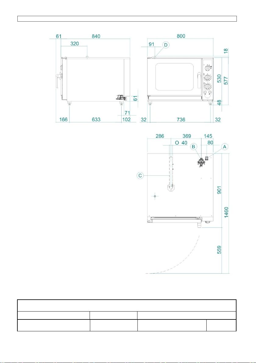
Pastry & Gastronomy 605 n°5 x (60x40) / n°4 x 1/1 GN
0.1A
DIMENSIONS
Models
Dimensions
Capacity and distance between trays.
5 x (60 x 40) - 4 x 1/1GN
Electric
cm 80 x 90 x h 58
n°5 x (60 x 40)
n°4 x 1/1 GASTRO NORM
67 mm
A Connessione elettrica
Electrical connection
Elektroanschluss
Branchement électrique
Conexión eléctrica
B Entrata acqua 3/4
Water inlet
3/4”
Wasserzufuhr 3/4”
Arrivée eau
3/4
Entrada agua 3/4
C Scarico cam. cottura 40mm
Water drainage
40mm
Wasserablauf 40mm
Vidange eau
40mm
Desagüe 40mm
D Sfiato camera cottura 60mm
Cooking chamber relief valve
60mm
Ablaßventil Garraum 60mm
Event chambre de cuisson
60mm
Evac. vahos càmara coccion 60mm
Pastry & Bakery Electromecanic 5-10 x (60x40)
3
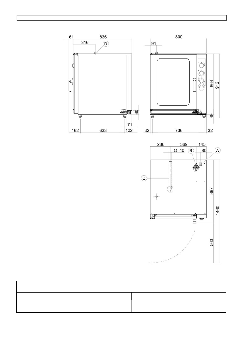
Pastry & Gastronomy 610 n°10 x (60x40) / n°9 x 1/1 GN
0.1B
DIMENSIONS
Models
Dimensions
Capacity and distance between trays.
10 x (60 x 40) - 9 x 1/1GN
Electric
cm 80 x 90 x h 92
n°10 x (60 x 40)
n°9 x 1/1 GASTRONORM
67 mm
A Connessione elettrica
Electrical connection
Elektroanschluss
Branchement électrique
Conexión eléctrica
B Entrata acqua 3/4
Water inlet
3/4”
Wasserzufuhr 3/4”
Arrivée eau
3/4
Entrada agua 3/4
C Scarico cam. cottura 40mm
Water drainage
40mm
Wasserablauf 40mm
Vidange eau
40mm
Desagüe 40mm
D Sfiato camera cottura 60mm
Cooking chamber relief valve
60mm
Ablaßventil Garraum 60mm
Event chambre de cuisson
60mm
Evac. vahos càmara coccion 60mm
Pastry & Bakery Electromecanic 5-10 x (60x40)
4
ISTRUZIONI PER L’INSTALLAZIONE
ITALIANO
INDICE
1.0
Dichiarazione di conformità
1.1
Direttiva europea ROHS 2011/65/UE
2.0
Installazione dell’apparecchio
2.2
Collegamento elettrico
2.2A
Tabella dati allacciamento elettrico
2.3
Collegamento idraulico entrata acqua
2.4
Collegamento idraulico scarico acqua
3.0
Automatismi di controllo e sicurezza
3.1
Sostituzione parti di ricambio
1.0- DICHIARAZIONE DI CONFORMITA’
Il Costruttore dichiara che gli apparecchi sono conformi alle prescrizioni CEE.
L’installazione dovrà essere effettuata in osservanza alle norme vigenti, soprattutto in merito
all’areazione dei locali e dei sistemi per l’evacuazione dei gas combusti.
N.B.: Il Costruttore declina ogni responsabilità in caso di danni diretti derivati da: uso non
corretto, errata installazione e da cattiva manutenzione.
1.1- DIRETTIVA EUROPEA ROHS 2011/65/UE
Questo apparecchio è contrassegnato in conformità alla Direttiva Europea 2011/65/UE, Waste
Electrical and Electronic Equipment (WEEE).
Assicurandosi che questo prodotto sia smaltito in modo corretto, l'utente contribuisce a prevenire le
potenziali conseguenze negative per l'ambiente e la salute.
Il simbolo sul prodotto o sulla documentazione di accompagnamento indica che
questo prodotto non deve essere trattato come rifiuto domestico ma deve essere
consegnato presso l'idoneo punto di raccolta per il riciclaggio di apparecchiature
elettriche ed elettroniche.
Disfarsene seguendo le normative locali per lo smaltimento dei rifiuti.
Per ulteriori informazioni sul trattamento, recupero e riciclaggio di questo prodotto,
contattare l'idoneo ufficio locale, il servizio di raccolta dei rifiuti domestici o il negozio
presso il quale il prodotto è stato acquistato.
Pastry & Bakery Electromecanic 5-10 x (60x40)
5
ISTRUZIONI PER L’INSTALLAZIONE
ITALIANO
2.0- INSTALLAZIONE DELL’APPARECCHIO
Leggere attentamente questo libretto che fornisce importanti indicazioni riguardanti la sicurezza
dell’installazione, l’uso e la manutenzione.
L’installazione dell’apparecchio deve essere eseguita, solo ed esclusivamente, da personale
qualificato seguendo le istruzioni riportate nel presente manuale e nel rispetto delle norme in
vigore.
Gli impianti dell’acqua,
dell’energia elettrica ed
i locali nei quali gli
apparecchi vengono
installati devono essere
eseguiti in conformità
alle corrispondenti
norme di installazione e
sicurezza.
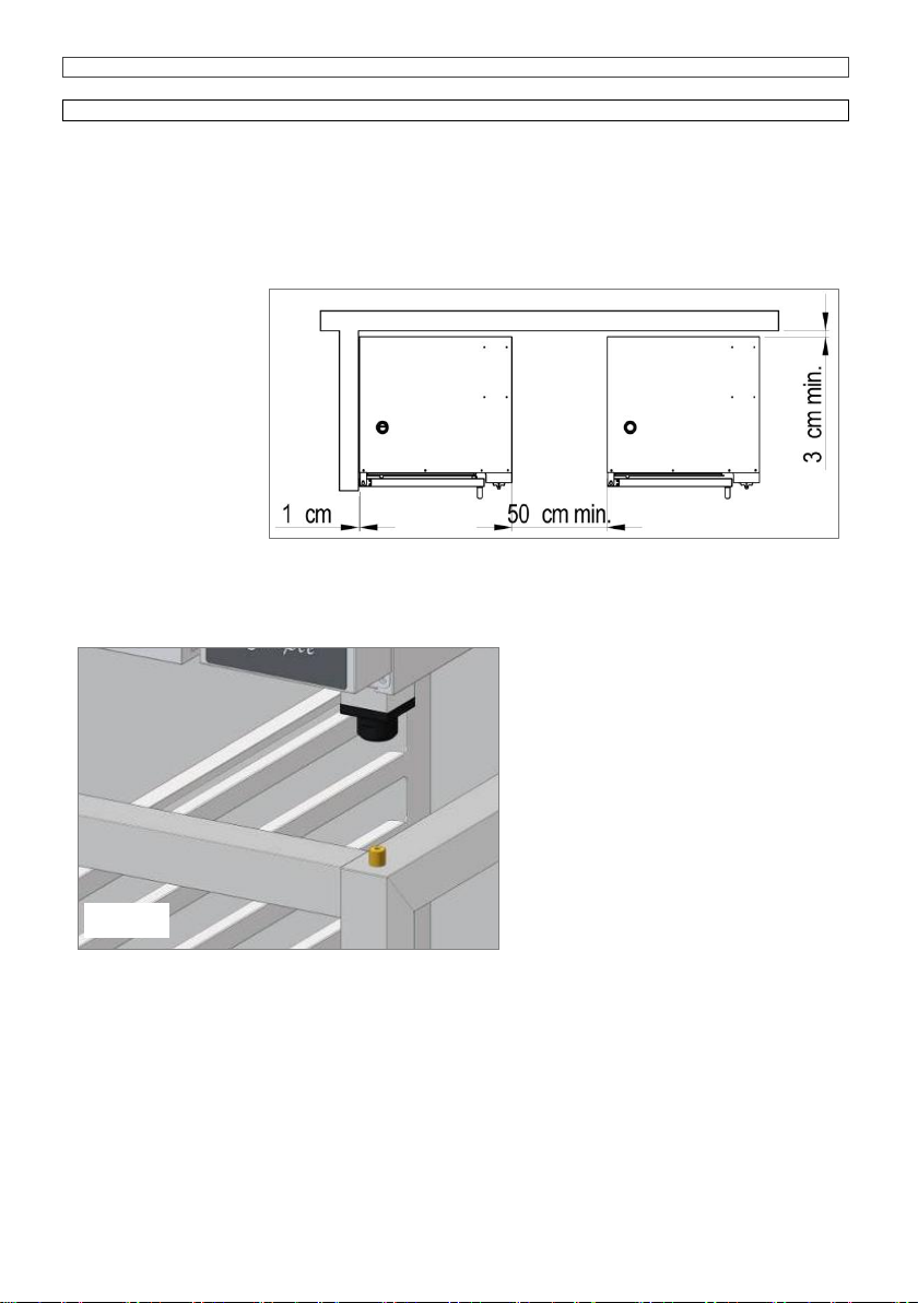
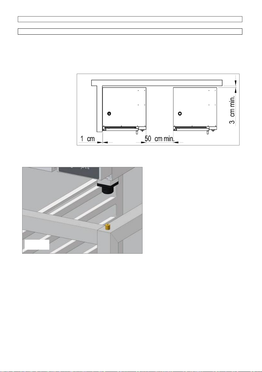
Collocare il forno in
ambiente aerato e
procedere alla messa a
livello agendo sui
piedini regolabili, in
modo tale che rimanga una distanza minima di 6cm tra il fondo del forno ed il piano di appoggio dei
piedini.
Installare l’apparecchio in una posizione che ne permetta l’accesso al lato dx per le operazioni di
installazione, manutenzione e assistenza
tecnica. Mantenere le distanze minime tra
le pareti del forno, (posteriore e laterale dx)
e le pareti in muratura o le altre
apparecchiature come indicato in figura
n°2.0.
Rimuovere manualmente le pellicole
protettive dalle parti in acciaio, prima di
mettere in funzione l’apparecchio, evitando
l’uso di sostanze abrasive e/o di oggetti
metallici.
Qualora il forno venga collocato sugli
appositi supporti, da noi forniti su richiesta,
fare attenzione che il foro centrale dei
piedini si innesti nel perno del supporto,
questo incastro ne garantisce la stabilità,
(Fig. 2.0A).
Fig. 2.0
Abb. 2.0
Fig. 2.0
Fig. 2.0A
Pastry & Bakery Electromecanic 5-10 x (60x40)
6
ISTRUZIONI PER L’INSTALLAZIONE
ITALIANO
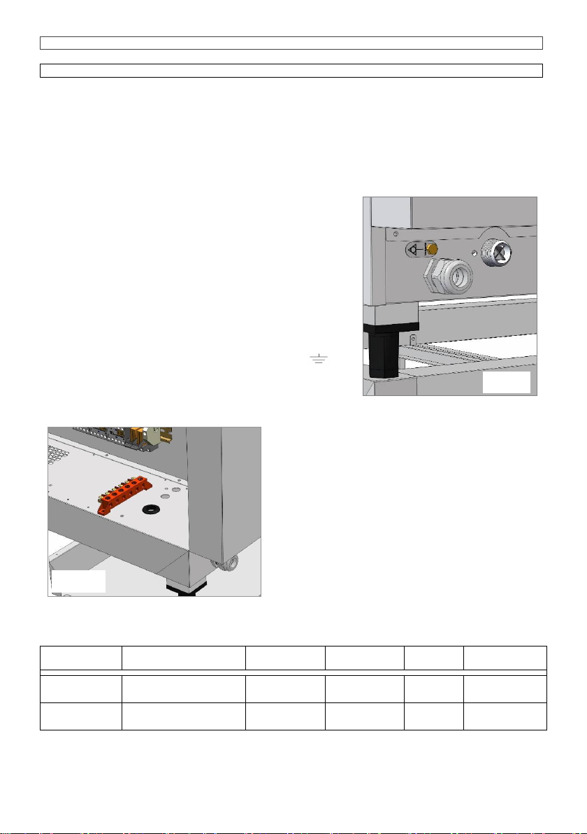
2.2-COLLEGAMENTO ELETTRICO
L’apparecchio consegnato è predisposto per il funzionamento alla tensione riportata sulla targhetta
“caratteristiche” applicata sul fianco dx dell’apparecchio.
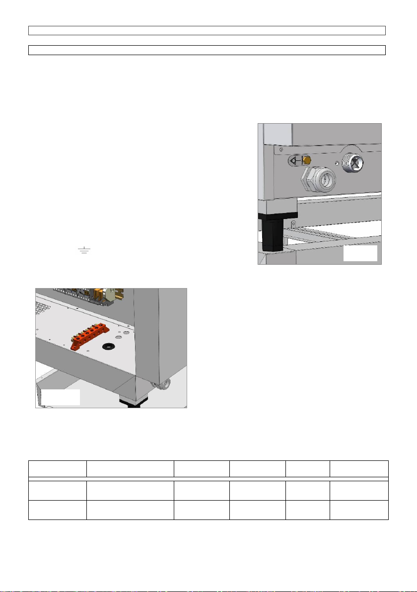
La morsettiera di allacciamento è accessibile dal lato dx dell’apparecchio, smontando il fianco di
rivestimento.
Prima di procedere all’applicazione del cavo, smontare la protezione in acciaio fissata al
basamento del forno con le relative viti, (vedi fig.2.2A) introdurre il cavo nel raccordo di bloccaggio
e introdurlo nel vano della morsettiera dal foro con
guarnizione del basamento in prossimità della stessa.
A collegamento elettrico eseguito rimontare la protezione in
acciaio precedentemente rimossa.
Il cavo flessibile, per il collegamento elettrico, deve avere
caratteristiche non inferiori a quello con isolamento in gomma
H07 RN-F con la sezione dei conduttori riportata nei dati
tecnici.
Installare, a monte dell’apparecchio, un interruttore
automatico di protezione e di portata adeguata, che abbia
un’apertura dei contatti superiore a 3 mm.
E’ indispensabile collegare l’apparecchiatura ad un efficiente
impianto di terra; a tale scopo sulla morsettiera di
allacciamento c’è il morsetto, con il relativo simbolo , al
quale deve essere connesso il conduttore di terra.
L’apparecchiatura deve trovare inserimento in un sistema
equipotenziale, (Fig. 2.2) la cui efficacia deve essere in
conformità alla normativa in vigore. Il collegamento deve essere eseguito tramite la vite collocata in
prossimità del pressacavo di alimentazione,
contrassegnata dalla sigla EQUIPOTENTIAL.
Il Costruttore declina ogni responsabilità qualora
questa importante norma antinfortunistica non
venga rispettata.
2.2A VERIFICA SENSO ROTAZIONE MOTORI
(solo per motori trifasi)
Verificare che il senso di rotazione dei ventilatori
corrisponda alla direzione della freccia riportata nel
pannello in acciaio inossidabile di convogliamento
aria, posto all’interno della camera di cottura, qualora
la rotazione risulti contraria, invertire tra loro due fasi
sulla morsettiera di alimentazione.
2.2A-TABELLA DATI TECNICI Allacciamento elettrico
Modelli
Potenza assorbita e
voltaggio
n° e potenza
motori
Potenza
riscaldante
Corrente
assorbita
Sez. cavo
alimentazione
5x(60 x 40)
electric
6 kW
400V+3N50/60 Hz
1 x 250 W
5.8 kW
10A
n°5 x 2.5 mm2
10x(60 x 40)
electric
12 kW
400V+3N50/60 Hz
2 x 250 W
11.6 kW
20 A
n°5 x 4 mm2
Fig. 2.2
Abb. 2.2
Fig. 2.2
Fig. 2.2A
Pastry & Bakery Electromecanic 5-10 x (60x40)
7
ISTRUZIONI PER L’INSTALLAZIONE
ITALIANO
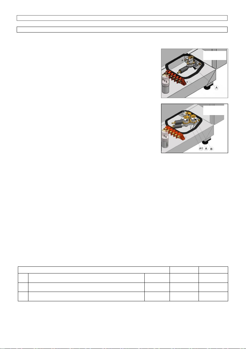
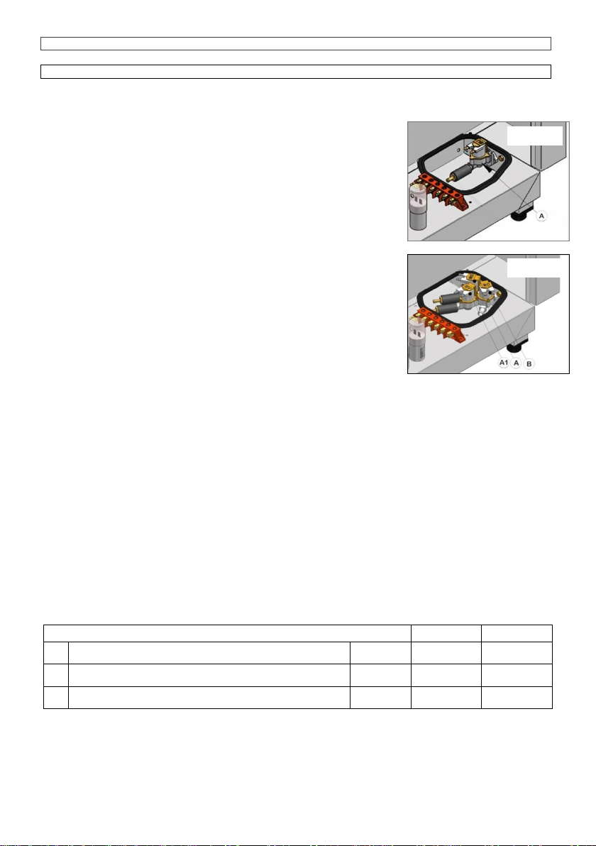
2.3 COLLEGAMENTO IDRAULICO - ENTRATA ACQUA (Fig. 2.3A, B)
I forni sono provvisti di un raccordo di entrata-acqua situato nel
retro dell’apparecchiatura. Porre sempre tra l’apparecchio e la
rete di alimentazione dell’acqua una valvola di intercettazione con
comando facilmente azionabile, si consiglia inoltre il montaggio di
un filtro a cartuccia sulla tubazione di entrata dell’acqua.
Nei modelli "convection+humidification" (fig. 2.3A), l’elettrovalvola
(A) alimenta il sistema di generazione del vapore nella camera di
cottura.
Nei modelli "combi direct" (fig. 2.3B),l’elettrovalvola (B) alimenta il
sistema di condensazione del vapore che fuoriesce da tubo di
scarico, l’elettrovalvole (A) e (A1) alimentano quello di
generazione del vapore nella camera di cottura
L’acqua di alimentazione deve essere idonea al consumo umano e
avere le seguenti caratteristiche:
Temperatura: compresa tra 15 –20°C
Durezza totale: compresa tra 4 e 8°Francesi, si consiglia di
installare sempre un decalcificatore a monte dell’apparecchio, atto
a mantenere il valore della durezza dell’acqua entro detti valori, Il
funzionamento del forno con acqua di durezza superiore porta alla
formazioni di incrostazioni calcaree sulle pareti della camera di cottura, eventuali interventi di
assistenza tecnica necessari alla riparazione di danni causati dal calcare, non saranno considerati
“in garanzia”.
Pressione: compresa tra 100 e 200 KPa (1 –2 bar).
N.B. valori di pressione più elevati comportano solo un dispendio del consumo di acqua e possono
compromettere il corretto funzionamento di alcuni componenti.
Concentrazione massima di ione cloruro (Cl-): inferiore a 150 mg/litro.
Concentrazione di Cloro (Cl2): inferiore a 0.2 mg/litro.
pH:maggiore di 7.
Conducibilità elettrica: compresa tra 50 e 2000 S/cm.
Attenzione: L’utilizzo di sistemi di trattamento dell’acqua che determinano valori diversi da quelli
sopra indicati non è ammesso pena il totale decadimento della garanzia. Eventuali impianti
dosatori di sostanze atte a evitare la formazione di incrostazioni nelle tubazioni (per esempio:
dosatori di polifosfati) sono altresì vietati perché possono compromettere il corretto funzionamento
dell’apparecchiatura.
2.3A TABELLA DATI TECNICI IMPIANTO ACQUA
605
610
A
Regolatore portata acqua ciclo misto
Fig. 2.3A,B
0.4 mm
0.5 mm
A1
Regolatore portata acqua ciclo vapore
Fig. 2.3B
0.5 mm
0.5 mm
B
Regolatore portata acqua condensazione
Optional
Fig. 3.0G
0.7 mm
0.7 mm
Fig. 2.3
Abb. 2.3
Fig. 2.3A
Fig. 2.3B
Pastry & Bakery Electromecanic 5-10 x (60x40)
8
ISTRUZIONI PER L’INSTALLAZIONE
ITALIANO
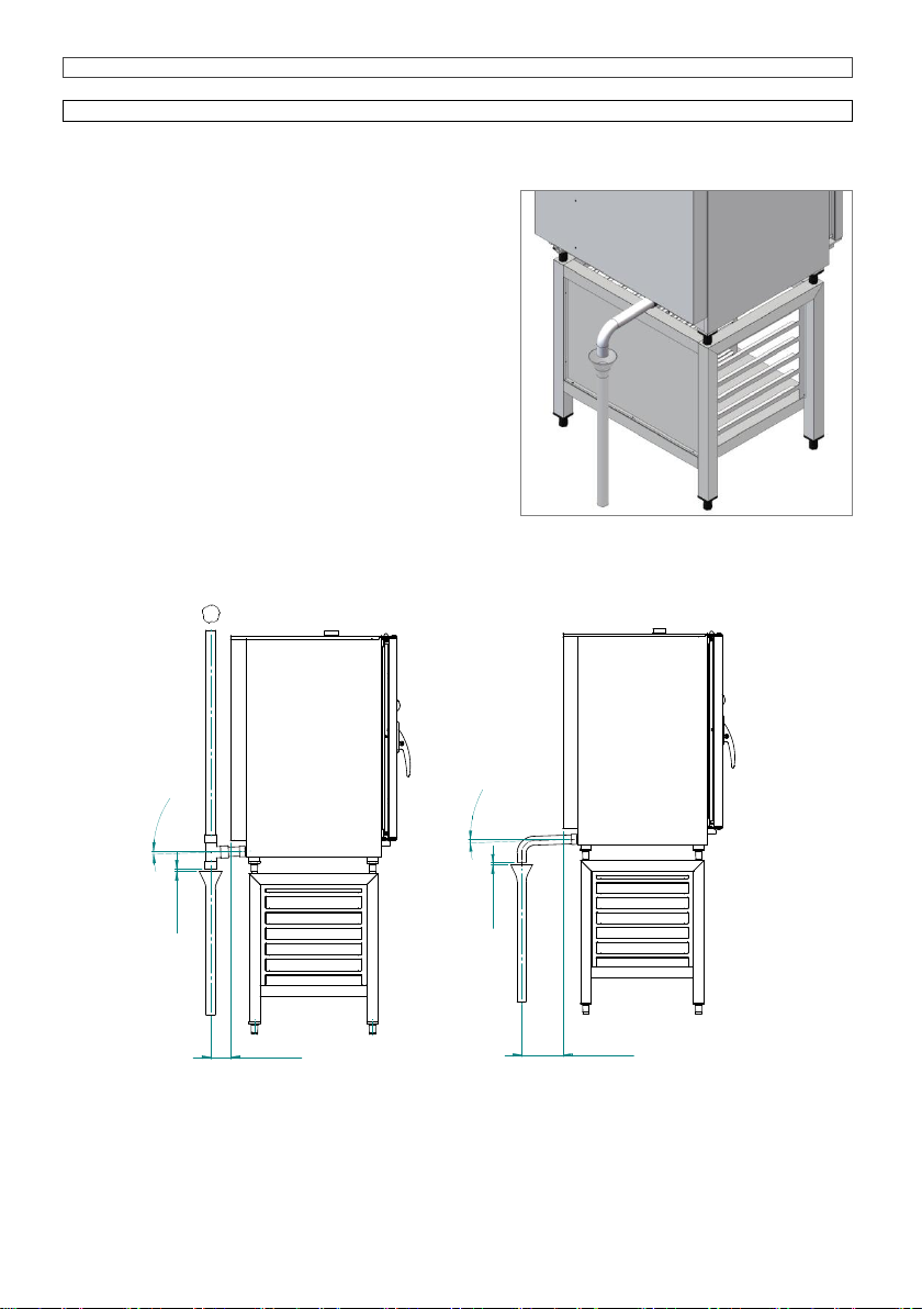
2.4 COLLEGAMENTO IDRAULICO - SCARICO ACQUA
I forni sono dotati di uno scarico acqua situato sul retro
dell’apparecchio; il collegamento idraulico deve essere
effettuato direttamente sull’estremità del tubo di scarico
in acciaio inox.
Lo scarico deve essere privo di sifone e realizzato con
tubi rigidi e resistenti alla temperatura di 110°C.
E’ assolutamente necessario che il diametro del tubo di
scarico non venga ridotto e che la sua tubazione sia a
pressione atmosferica, con l’opportuna presa d’aria a
imbuto.
L’eventuale intasamento del tubo di scarico può
provocare uscita di vapore dalla porta e cattivi odori
nella camera di cottura.
Attenzione: L’impianto di scarico deve essere
installato in modo tale da evitare che eventuali vapori
emessi dalla presa d’aria a imbuto “air break”
raggiungano le aperture di aereazione presenti sul
fondo del forno. (Fig. 2.4 e 2.4A)
2°
min.
1> cm
> 50 cm
2°
min.
> 1 cm
< 30 cm
Fig. 2.4
Abb. 2.4
Fig. 2.4
Fig. 2.4A
Pastry & Bakery Electromecanic 5-10 x (60x40)
9
ISTRUZIONI PER L’INSTALLAZIONE
ITALIANO
3.0-AUTOMATISMI DI CONTROLLO E SICUREZZA
I forni sono dotati di una serie di automatismi di controllo e sicurezza dei circuiti elettrici ed idraulici
3.0A Fusibile da 2A: è inserito nel circuito ausiliario per la protezione da corto circuito
dell’impianto elettrico ed è alloggiato nell’apposito supporto collocato sulla staffa di fissaggio dei
contattori.
3.0D Protezione motore: una sonda termica disinserisce il motore qualora per motivi diversi si
possa manifestare un sovraccarico, l’intervento della
protezione determina l’arresto del motore e il
conseguente disinserimento delle resistenze o del
bruciatore di gas del riscaldamento.
Il ripristino della sonda avverrà automaticamente con
la diminuzione della temperatura del motore.
3.0E Termostato sicurezza camera forno:
disinserisce le resistenze riscaldanti nei modelli
elettrici o chiude la valvola del gas nei relativi
apparecchi, in caso di anomalie derivate da
surriscaldamento, il ripristino dovrà essere eseguito
manualmente dopo la verifica delle cause che ne
hanno causato l’intervento.
3.0F Interruttore apertura porta: arresta il
funzionamento del forno quando viene aperta la
porta.
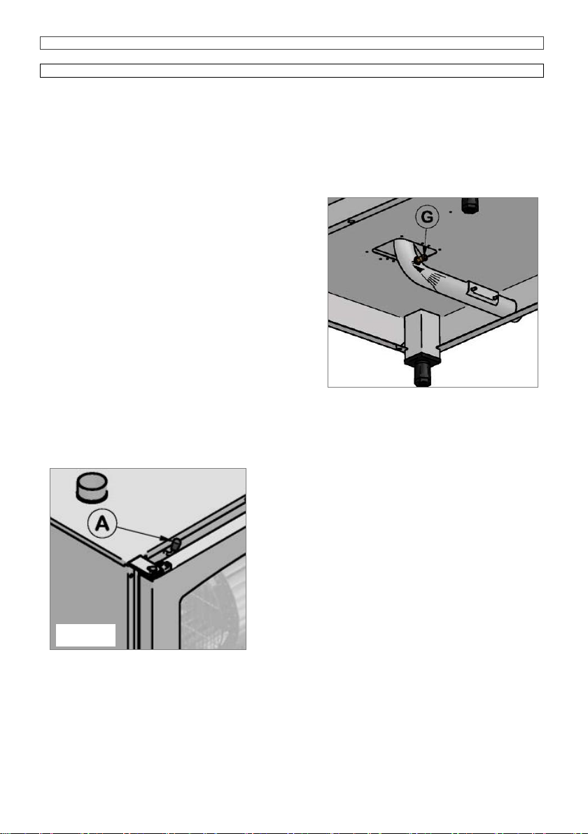
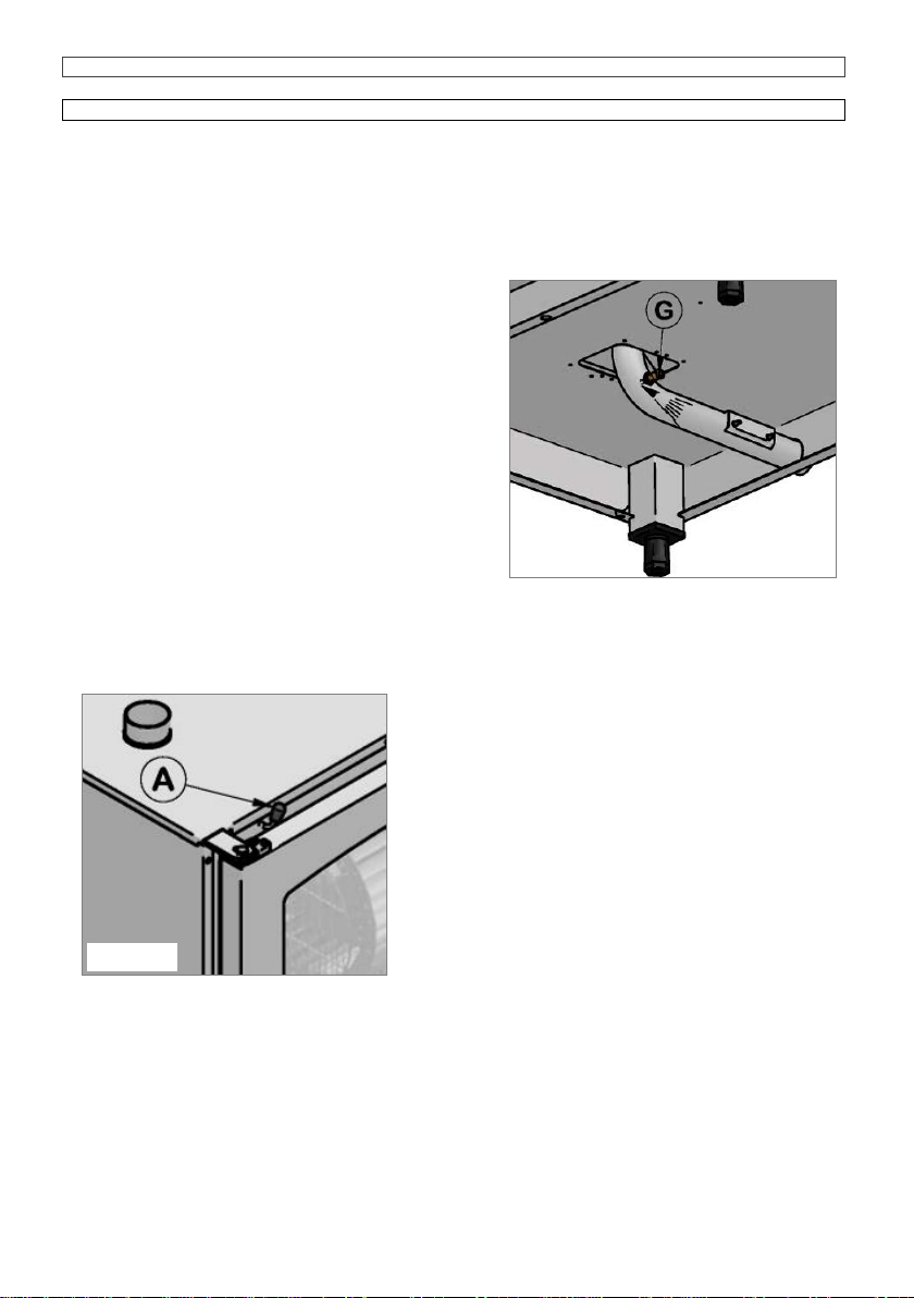
3.0G Sistema termostatico per la condensazione dei vapori di scarico (Optional): è
composto di un elettrovalvola, comandata da un termostato il cui sensore è alloggiato a contatto
con lo scarico.
L’elettrovalvola tramite l’iniettore (G) provvede ad immettere acqua fredda nel tubo di scarico per
condensare il vapore quando viene raggiunta la
temperatura di 90°C, (Fig. 3.0G).
3.0H Valvola sfiato camera : ha la funzione di
regolare l’umidità all’interno della camera di cottura e
viene attivata manualmente tramite il pomello (A),
situato sopra la porta. (Fig. 3.0H).
Fig. 3.0G
Abb. 3.0G
Fig. 3.0G
Fig. 3.0H

Pastry & Bakery Electromecanic 5-10 x (60x40)
10
ISTRUZIONI PER L’INSTALLAZIONE
ITALIANO
3.1-SOSTITUZIONE PARTI DI RICAMBIO
Prima di procedere alla sostituzione delle parti di ricambio è necessario, ai fini della sicurezza,
disinserire l’interruttore elettrico di protezione e chiudere la valvola di intercettazione-acqua e gas
installate a monte dell’apparecchio.
CONTROLLO DELLE FUNZIONI
Mettere in funzione l’apparecchio come da “ISTRUZIONI PER L’UTENTE”.
Eseguire una prova di tenuta delle condutture idriche e quelle del gas.
E’ indispensabile spiegare all’utente il funzionamento dell’apparecchiatura e consegnargli il libretto
istruzioni a cui si dovrà attenere nell’uso.
Pastry & Bakery Electromecanic 5-10 x (60x40)
11
CONVECTION - STEAM OVEN
INSTRUCTIONS FOR THE INSTALLATION
ENGLISH
605 / 610
Mod. Analogic
UK

Pastry & Bakery Electromecanic 5-10 x (60x40)
12
INSTRUCTIONS FOR THE INSTALLATION
ENGLISH
INDEX
1.0
Conformity of declaration
1.1
European directive ROHS 2011/65/UE
2.0
Appliance installation
2.2
Electrical connection
2.2A
Technical data for electrical connection
2.3
Hydraulic connection –water inlet
2.4
Hydraulic connection- water drainage
3.0
Control and safety devices
3.1
Spare parts replacing
1.0-
CONFORMITY OF DECLARATION
The Manufacturer declares that the appliances conform to the EEC norms.
They must be installed in accordance with current standards, especially regarding aeration of the
premises and the exhaust gas evacuation system.
Note: The Manufacturer declines all and every responsibility for any direct damages
caused by: an incorrect use, wrong installation or bad maintenance.
1.1-EUROPEAN DIRECTIVE ROHS 2011/65/UE
This appliance is marked according to the European directive 2011/65/UE on Waste Electrical and
Electronic Equipment (WEEE).
By ensuring this product is disposed correctly, you will help prevent potential negative
consequences for the environment and human health, which could otherwise be caused by
inappropriate waste handling of this product.
The symbol on the product, or on the documents accompanying the product, indicates
that this appliance may not be treated as household waste. Instead it shall be handed
over to the applicable collection point for the recycling of electrical and electronic
equipment.
Disposal must be carried out in accordance with local environmental regulations for
waste disposal.
For more detailed information about treatment, recovery and recycling of this product,
please contact your local city office, your household waste disposal service or the shop where you
purchased the product.
Pastry & Bakery Electromecanic 5-10 x (60x40)
13
INSTRUCTIONS FOR THE INSTALLATION
ENGLISH
2.0-
INSTALLING THE APPLIANCE
Read this handbook through carefully as it provides important information to guarantee a safe
installation, use and maintenance.
The appliance must be installed only and exclusively by qualified personnel following the
instructions given
herein and in
compliance with current
laws in force.
The water, electricity
and the premises on
which the appliances
are installed comply
with the relative
installation and safety
standards.
Install the oven on
aerated premises and
level with the
adjustable feet, keeping at least 6cm between the bottom of the oven and the supporting surface
on which the feet stand. Install the appliance in a position that
allows access to the right side for
installation, maintenance and technical
assistance.
Maintain the minimum distances between
the oven walls, (rear and right side) and
either the brick walls or the other
appliances, as illustrated in figure 2.0A.
Take the protective film off the stainless
steel parts by hand before starting the
appliance. Do not use abrasive substances
and/or metal objects.
If the oven is placed on its supports,
supplied by us on request, make sure the
centre hole of the feet snap on to the
support pin which will guarantee stability,
(Fig. 2.0A).
Fig. 2.0
Fig. 2.0A
Pastry & Bakery Electromecanic 5-10 x (60x40)
14
INSTRUCTIONS FOR THE INSTALLATION
ENGLISH
2.2-ELECTRICAL CONNECTION
When the appliance is delivered it is set to work at the voltage given on the rating plate affixed on
the right side of the appliance.
The terminal board used for connecting can be accessed from the right of the appliance, removing
the side panel. Before connecting the cable, remove the steel protection fixed to the ovens base
with its specific screws, (see Fig. 2.2A)insert the cable in the
clamp-connector and then in the terminal board zone,
passing through the hole with the gasket near the terminal
board. Once the electric connection has been carried out,
reassemble the steel protection previously removed.
The specifications of the flexible cable for the electrical
connection should be no lower than those of the type with
rubber insulation H07 RN-F, with the cross section of the
wires as given in the technical data.
Install a circuit breaker of a suitable capacity upstream from
the appliance, making sure it has an opening between the
contacts of at least 3-mm.
It is essential to connect the appliance to an effective earthing
system; (Fig. 2.2) for this purpose the relative terminal with
the symbol to which the earth wire is to be connected is
on the terminal board.
The effectiveness of the equipotential system of which the appliance is part of, must conform to
current standards. Connect using the screw you find near the power cable’s relief cable strain,
marked with the word EQUIPOTENTIAL.
The Manufacturer declines all and every
responsibility if this important accident
prevention norm is not complied with
2.2A-CHECKING MOTOR ROTATION DIRECTION
(only for three-phase motors).
Check that the fans’ rotation direction is the same as
that of the arrow on the stainless steel air-conveying
panel, located inside the oven. If they are rotating in
the opposite direction, reverse two phases on the
supply terminal board.
2.2ATECHNICAL DATA TABLE Electric connection
Models
Power loading and
voltage
no. and motor
power
Heating power
Absorbed
current
Feed cable
section
5x(60 x 40)
electric
6 kW
400V+3N50/60 Hz
1 x 250 W
5.8 kW
10A
n°5 x 2.5 mm2
10x(60 x 40)
electric
12 kW
400V+3N50/60 Hz
2 x 250 W
11.6 kW
20 A
n°5 x 4 mm2
Fig. 2.2A
Fig. 2.2
Pastry & Bakery Electromecanic 5-10 x (60x40)
15
INSTRUCTIONS FOR THE INSTALLATION
ENGLISH
2.3-HYDRAULIC CONNECTION –WATER INLET (Fig. 2.3A, B)
The ovens have a water inlet coupling at the back.
Always install an on-off valve between the appliance and the water
mains, making sure it is easy to operate.
We also suggest installing a cartridge filter on the water inlet pipe.
Always connect to the cold water.
In "convection + humidification" models(fig. 2.3A), the solenoid valve
(A) supply the system that generates steam for cooking chamber.
In "combi direct" models(fig. 2.3B), the solenoid valve (B) supply the
steam condensation system that comes out of the drainpipe, while
solenoid valves (A) and (A1) supplies the system that generates
steam for cooking chamber.
The water must be suitable to human use with the following
characteristics:
Temperature:
included between 15 –20°C
Total hardness:
included between 4 and 8 °French degree, it is
advisable to install a softener upstream from the appliance that will
maintain the hardness level at the mentioned values. The oven’s
running with water that has a higher hardness level will not be long
before scale forms on the walls of the oven and in this case the technical assistance required to
repair such damage is not covered by the guarantee.
Pressure:
included between 100 and 200 KPa (1 –2 bar).
Attention higher water pressure values result in increased water consumption and can compromise
the correct functioning of some components.
Maximum chloride concentration (Cl-):
less than 150 mg/litre.
Chlorine concentration (Cl2):
less than 0.2 mg/litre.
pH:
more than 7.
Water conductivity:
included between 50 and 2000
S/cm.
Attention:
Water treatment systems that bring to different values to the ones above mentioned
automatically invalidate the guarantee. The use of dosing systems designed to prevent the build-up
of lime-scale in pipes (i.e. polyphosphate dosing systems) is also prohibited since it may impair the
performance of the appliance.
2.3A TECNICAL DATA TABLE FOR THE WATER SYSTEM
605
610
A
Combined cycle water flow rate regulator
Fig. 2.3A,B
0.4 mm
0.5 mm
A1
Steam cycle water flow rate regulator
Fig. 2.3B
0.5 mm
0.5 mm
B
Condensation flow rate regulator
Optional
Fig. 3.0G
0.7 mm
0.7 mm
Fig. 2.3A
Fig. 2.3B

Pastry & Bakery Electromecanic 5-10 x (60x40)
16
INSTRUCTIONS FOR THE INSTALLATION
ENGLISH
2.4-PLUMBING –WATER DRAINAGE
Drainage for the water is at the back of the oven and
must be connected directly to the end of the stainless
steel drainpipe.
The drain must have no trap and be made in rigid pipes
that can withstand a temperature of 110°C.
Under no circumstances must pipe diameter be reduced.
The actual pipe should be at atmospheric pressure with
the appropriate funnel type air intake.
If the drainpipe is clogged for any reason steam can
escape from the door and bad smells can be created
inside in the oven.
Important:
The drain system must be installed so that
any vapours coming from the open drain do not enter the
aeration vents under the appliance. (Fig. 2.4 and 2.4A).
2°
min.
> 1 cm
< 30 cm
2°
min.
1> cm
> 50 cm
Fig. 2.4
Fig. 2.4A
Pastry & Bakery Electromecanic 5-10 x (60x40)
17
INSTRUCTIONS FOR THE INSTALLATION
ENGLISH
3.0-CONTROL AND SAFETY DEVICES
The ovens are equipped with a set of control and safety devices for the electric and hydraulic
circuits.
3.0A 2A fuse:
it is in the auxiliary circuit to protect against short circuiting of the electrical system
and is inside its own support on the contactor’s fixing bracket.
3.0D Motor overload protection:
a thermal probe
disengages the motor when, for various reasons,
there is an overload.
When the overload protection triggers it stops the
motor and also disconnects the heating elements or
the gas valve.
The probe is reset automatically when motor
temperature drops.
3.0E Oven safety thermostat:
disconnects the
heating element or the gas valve when anomalies
related to overheating occur.
Subsequent re-set will have to be done manually
when causes for thermostat operation have been
determined.
3.0F Door micro switch:
it stops the oven working when the door is opened.
3.0G Thermostat system for condensation of discharge steam (Optional):
it comprises a
solenoid valve controlled by a thermostat whose sensor is housed in contact with the discharge.
The solenoid valve, via the injector (G), lets cold water into the drainpipe to condense the steam
when a temperature of 90°C is reached, (Fig. 3.0G).
3.0H Oven relief valve (Optional):
(Optional) its job
is to adjust humidity inside the cooking chamber.
The valve is manually activated acting on the knob (A)
(Fig.3.0H)on top of the door.
Fig. 3.0G
Fig. 3.0H

Pastry & Bakery Electromecanic 5-10 x (60x40)
18
INSTRUCTIONS FOR THE INSTALLATION
ENGLISH
3.1-REPLACING SPARE PARTS
Before starting to replace spare parts make sure, for safety reasons, that the electricity main switch
is off and that the water on-off valve is closed and that (for gas powered ovens) the gas supply is
turned off.
CHECKING THE FUNCTIONS
Start the appliance following the “INSTRUCTIONS FOR THE USER”.
Test the water pipes for leaks.
It is essential to explain to the user exactly how the appliance works and to supply him with the
instruction handbook that he must follow when using the oven.
Pastry & Bakery Electromecanic 5-10 x (60x40)
19
HEISSLUFTDÄMPFER
ANLEITUNGEN FÜR DEN INSTALLATEUR
DEUTSCHE
605 / 610
Mod. Analogic
DE
Pastry & Bakery Electromecanic 5-10 x (60x40)
20
ANLEITUNGEN FÜR DEN INSTALLATEUR
DEUTSCHE
INHALTSVERZEICHNIS
1.0
Konformitätserklärung
1.1
Europäischen richtlinie ROHS 2011/65/UE
2.0
Geräteinstallation
2.2
Elektroanschluss
2.2A
Technische Daten für Elektroanschluss
2.3
Anschluss an das Wassernetz –Wasserzufuhr
2.4
Anschluss an das Wassernetz –Wasserablauf
3.0
Kontroll- und Sicherheitsautomatismen
3.1
Austausch der Ersatzteile
1.0-KONFORMITÄTSERKLÄRUNG
Der Hersteller bestätigt, dass die Geräte den EU-Vorschriften entsprechen.
Die Installation muss, insbesondere bezüglich der Belüftung der Räume und der Abgasleitung,
gemäß den gültigen Normen durchgeführt werden.
Achtung: Der Hersteller haftet nicht für direkte Schäden, die durch unsachgemäße
Bedienung, falsche Installation, oder mangelnde Wartung verursacht worden sind.
1.1-EUROPÄISCHE RICHTLINIE ROHS 2011/65/UE
In Übereinstimmung mit den Anforderungen der Europäischen Richtlinie 2011/65/UE über Elektro-
und Elektronik-Altgeräte (WEEE) ist vorliegendes Gerät mit einer Markierung versehen.
Sie leisten einen positiven Beitrag für den Schutz der Umwelt und die Gesundheit des Menschen,
wenn Sie dieses Gerät einer gesonderten Abfallsammlung zuführen.
Im unsortierten Siedlungsmüll könnte ein solches Gerät durch unsachgemäße Entsorgung negative
Konsequenzen nach sich ziehen.
Auf dem Produkt oder der beiliegenden Produktdokumentation ist folgendes Symbol
einer durchgestrichenen Abfalltonne abgebildet. Es weist darauf hin, dass eine
Entsorgung im normalen Haushaltsabfall nicht zulässig ist Entsorgen Sie dieses
Produkt im Recyclinghof mit einer getrennten Sammlung für Elektro- und
Elektronikgeräte.
Die Entsorgung muss gemäß den örtlichen Bestimmungen zur Abfallbeseitigung
erfolgen.
Bitte wenden Sie sich an die zuständigen Behörden Ihrer
Gemeindeverwaltung, an den lokalen Recyclinghof für Haushaltsmüll oder an den Händler, bei
dem Sie dieses Gerät erworben haben, um weitere Informationen über Behandlung, Verwertung
und Wiederverwendung dieses Produkts zu erhalten.
This manual suits for next models
3
Table of contents
Languages:
Other Inoxtrend Oven manuals


Popular Oven manuals by other brands


Baumatic
Baumatic B300SS User instruction manual

Vulcan-Hart
Vulcan-Hart VCV-13 Installation & operation manual

Toscana
Toscana MPO 18 Installation, operation, maintenance and owner's manual

Smeg
Smeg SCP372X-8 manual

Barazza
Barazza CITY STEEL 1FCYP9 instruction manual

GEAppliances
GEAppliances 47065 installation instructions


