InPOWER DCS35 Series User manual
Page
1 of 2
DCS35/36 Owners Manual
Document: OM-24 Version Code: E
Date: May 26, 2004 Date: March 27, 2017
InP
O
W
ER
the systems people
InPower LLC
8311 Green Meadows Dr.
Lewis Center, Ohio 43015
740-548-0965
www.InPowerDirect.com
© Copyright 2017 InPower LLC
OWNERS MANUAL
DCS35/36 Series
Hall-Effect Current Sensors
INTRODUCTION
The DCS35/36 Series family of Hall-effect DC current sensors is designed to output current readings to electronic
instruments or vehicle systems. Although typically used in vehicle and marine applications to measure battery currents,
they are suitable for monitoring bidirectional current in a variety of DC circuits. The sensors measure either positive and
negative or simply positive current values. Please see the below table for a list of available current ranges and outputs.
DC Current Sensor Models
Model Current Range Output Model Current Range Output
DCS35-100-1 ± 100 amps 2.5 ± 2.0 V DCS35-400-1 ± 400 amps 2.5 ± 2.0 V
DCS35-200-1 ± 200 amps 2.5 ± 2.0 V DCS35-500-1 ± 500 amps 2.5 ± 2.0 V
DCS35-300-1 ± 300 amps 2.5 ± 2.0 V DCS35-600-1 ± 600 amps 2.5 ± 2.0 V
DCS35-1000-1 ± 1000 amps 2.5 ± 2.0 V
DCS35-100-2 ± 100 amps 2.5 ± 2.5 V DCS35-400-2 ± 400 amps 2.5 ± 2.5 V
DCS35-200-2 ± 200 amps 2.5 ± 2.5 V DCS35-500-2 ± 500 amps 2.5 ± 2.5 V
DCS35-300-2 ± 300 amps 2.5 ± 2.5 V DCS35-600-2 ± 600 amps 2.5 ± 2.5 V
DCS36-100-1 0 to 100 amps 0.5 to 4.5 V DCS36-400-1 0 to 400 amps 0.5 to 4.5 V
DCS36-150-1 0 to 150 amps 0.5 to 4.5 V DCS36-500-1 0 to 500 amps 0.5 to 4.5 V
DCS36-200-1 0 to 200 amps 0.5 to 4.5 V DCS36-600-1 0 to 600 amps 0.5 to 4.5 V
DCS36-250-1 0 to 250 amps 0.5 to 4.5 V DCS36-1000-1 0 to 1000 amps 0.5 to 4.5 V
DCS36-300-1 0 to 300 amps 0.5 to 4.5 V
DCS36-100-2 0 to 100 amps 0 to 5.0 V DCS36-400-2 0 to 400 amps 0 to 5.0 V
DCS36-200-2 0 to 200 amps 0 to 5.0 V DCS36-500-2 0 to 500 amps 0 to 5.0 V
DCS36-250-2 0 to 250 amps 0 to 5.0 V DCS36-600-2 0 to 600 amps 0 to 5.0 V
DCS36-300-2 0 to 300 amps 0 to 5.0 V DCS36-1000-2 0 to 1000 amps 0 to 5.0 V
SPECIFICATIONS
Sensor Type: Open loop Hall-effect
Linearity: 1.5%
Supply Voltage Range: +7 to +20Vdc
Current consumption: 8.1 milliamps maximum
Output to Meter: See above Model Chart
Operating Temperature: -40°C to +125°C
Storage Temperature: -40°C to +125°C
Aperture Size: 1.23 inches
Weight: 0.30 lbs
Dimensions: 2.66 x 2.10 x 1.10
Connector System: Packard Sealed Metri-Pak 150. Mating plug not supplied with sensor. See
Technical Bulliten TB-31 for details.
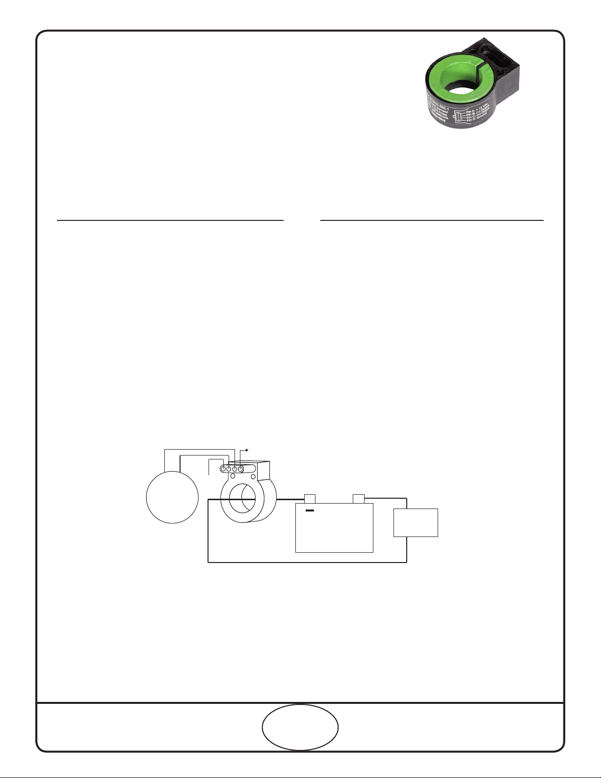
BATTERY
+12V
GND
SIGNAL GND
SIGNAL OUTPUT
INSTRUMENT
SYSTEMS +LOADS
System Diagram

Page
2 of 2
DCS35/36 Owners Manual
Document: OM-24 Version Code: E
Date: May 26, 2004 Date: March 27, 2017
InP
O
W
ER
the systems people
InPower LLC
8311 Green Meadows Dr.
Lewis Center, Ohio 43015
740-548-0965
www.InPowerDirect.com
© Copyright 2017 InPower LLC
INSTALLATION
1. Getting Started
Before starting, make sure you have the correct connector plug parts, cable, sensor mouting bracket and screws, and
tools. Exercise appropriate caution when working with vehicle battery systems and ensure battery is disconnected during
installation.
Determine the location for mounting the sensor and the required cable length and routing to the meter. Avoid mounting
the sensor close ot very hot engine parts such as the exhaust manifold.
2. Instaling the Sensor
Mount the sensor and route the battery cable through the aperture. The sensor may be secured to the battery cable using
tie wraps or a customer-made mounting bracket. If using a bracket, use 3 #6 self-tapping screws to attach the sensor via
the three bracket holes. Make sure the screws do not protrude more than 0.30 inches into the sensor.
Be sure to mount the sensor in the proper direction to ensure correct measurements of charging (plus) and discharging
(minus) battery current. See below diagram for suitable sensor mounting locations:
3. Installing the Cable
The DCS Series current sensors use a four pin Packard Sealed Metri-Pak 150 connector. You may either supply your
own or purchase a pre-made 12 inch pigtail from InPower, LLC (P/N: CA-DCS-12). Pin A is for +12V power, Pins B is
the signal output, pin C is the signal ground, and Pin D is for power ground. See Mechanical Drawing below for further
details.
4. Check Sensor & Meter Operation
Apply power to the sensor and verify that the meter is working correctly by checking battery charing and discharging
conditions. We recommend using a clamp-on ammeter, such as a Fluke, when verifying proper operation.
Mechanical Drawing
All dimensions in inches. Not to scale.
2.10
1.10
2.66
1.23 Dia.
77°
Mounting holes
for optional
mounting bracket.
Three places. Use
Phillips Plastite
screws #6 x 3/8
0
.85 Radius
0.83 0.83
BOTTOM VIEW
SIDE VIEW
TOP VIEW
0.65
TPA Connector Seal
Terminal (Female)
Cable Seal
Cable
Metri-Pak 150 Male Connector
(on body of DCS35/36)
View looking into connector
Metri-Pak Female Connector Assembly
ABCD
A
B
C
D
A: +Vdc Supply Power
B: Signal Output
C: Signal Ground
D: Power Ground
BATTERY
-+
LOADS
S
ENSOR
CABLE
SENSOR DIRECTION
S
ENSOR
CABLE
S
ENSOR
CABLE
This manual suits for next models
31


