Detcon DM-500IS OLED Series User manual

Detcon Model Series
DM-500IS OLED
Explosion Proof and Intrinsically Safe Toxic Gas Sensors
Operator’s Installation and Instruction Manual
DETCON, Inc.
4055 Technology Forest Blvd. Suite 100,
The Woodlands, Texas 77381
Ph.281.367.4100 / Fax 281.298.2868
www.detcon.com
August 17, 2015 • Document #4517 • Revision 0.1

DM-500IS
DM-500IS Instruction Manual ii
This page left intentionally blank

DM-500IS
DM-500IS Instruction Manual iii
Table of Contents
1.0 Description................................................................................................................................................ 2
1.1 Sensor Technology............................................................................................................................... 2
1.2 Universal Microprocessor Control Transmitter Circuit........................................................................ 3
1.3 Base Connector Board.......................................................................................................................... 3
1.4 Explosion Proof Enclosure................................................................................................................... 3
2.0 Principle Of Operation............................................................................................................................ 4
3.0 Application ............................................................................................................................................... 5
3.1 Sensor Placement/Mounting................................................................................................................. 5
3.2 Interference Data.................................................................................................................................. 5
3.3 Interference Gas List............................................................................................................................ 6
3.4 Interference Gas Table (page 1 of 5).................................................................................................... 7
4.0 Specifications.......................................................................................................................................... 12
5.0 Installation.............................................................................................................................................. 13
5.1 Field Wiring Table (4-20 mA output)................................................................................................ 13
5.2 Sensor Location.................................................................................................................................. 13
5.3 Local Electrical Codes........................................................................................................................ 15
5.4 Installation Procedure......................................................................................................................... 15
5.5 Remote Mounting Applications ......................................................................................................... 16
6.0 Startup.................................................................................................................................................... 17
6.1 Initial Operational Tests..................................................................................................................... 17
7.0 Operating Software & Magnetic Interface.......................................................................................... 18
7.1 Normal Operation............................................................................................................................... 18
7.2 Calibration Mode................................................................................................................................ 18
7.2.1 Zero Adjustment ......................................................................................................................... 18
7.2.2 Span Adjustment......................................................................................................................... 18
7.3 Program Mode.................................................................................................................................... 18
7.3.1 Program Status........................................................................................................................... 18
7.3.2 Calibration Level Adjustment..................................................................................................... 18
7.4 Programming Magnet Operating Instructions.................................................................................... 19
8.0 Software Flow Chart ............................................................................................................................. 20
9.0 Calibration.............................................................................................................................................. 20
9.1 Calibration Procedure – Zero............................................................................................................. 20
9.2 Calibration Procedure – Span............................................................................................................. 21
9.3 Additional Notes................................................................................................................................. 22
9.4 Calibration Frequency........................................................................................................................ 22
10.0 Status of Programming, Calibration Level and Sensor Life.............................................................. 22
11.0 Program Features.................................................................................................................................. 23
12.0 Universal Transmitter Feature (Re-Initialization)............................................................................. 24
13.0 Trouble Shooting ................................................................................................................................... 25
14.0 Spare Parts List...................................................................................................................................... 27
15.0 Warranty................................................................................................................................................ 29
16.0 Service Policy ......................................................................................................................................... 29

DM-500IS
DM-500IS Instruction Manual iv
17.0 Revision History..................................................................................................................................... 30
Table of Figures
Figure 1 DM-500IS Sensor ...............................................................................................................................2
Figure 2 Construction of Electrochemical Sensor.............................................................................................2
Figure 3 Universal Microprocessor Control Transmitter circuit.......................................................................3
Figure 4 Base connector board..........................................................................................................................3
Figure 5 Explosion-Proof Enclosure.................................................................................................................4
Figure 6 Functional Block Diagram..................................................................................................................4
Figure 7 Typical Installation .............................................................................................................................14
Figure 8 Typical Outline and Mounting Dimensions........................................................................................15
Figure 9 Sensor wiring......................................................................................................................................16
Figure 10 Remote wiring diagram.....................................................................................................................16
Figure 11 Programming magnet........................................................................................................................19
Figure 12 Programming Switch locations.........................................................................................................19
Figure 13 Software Flow Chart.........................................................................................................................20
Figure 14 Spare parts diagram...........................................................................................................................27
List of Tables
Table 1 Model #, Gas Name and Symbol..........................................................................................................1
Table 2 Sensor cell specifications .....................................................................................................................12
Table 3 Field wiring Table................................................................................................................................13
Table 4 Over-current Protection per AWG.......................................................................................................13
Table 5 IS Sensor Head / Plug-in Replacement Sensor Cell.............................................................................28
Shipping Address 4055 Technology Forest Blvd. Suite 100,., The Woodlands Texas 77381
Mailing Address: P.O. Box 8067, The Woodlands Texas 77387-8067

DM-500IS
DM-500IS Instruction Manual Rev 0.1 Page 1 of 30
This manual covers the following Models...
Table 1 Model #, Gas Name and Symbol
Model # Gas Name Symbol
DM-500-C2H3O Acetaldehyde C2H3O
DM-500-C2H2 Acetylene C2H2
DM-500-C3H3N Acrylonitrile C3H3N
DM-500-NH3 (-20°C) Ammonia NH3
DM-501-NH3 (-40°C) Ammonia NH3
DM-502-NH3 Ammonia (continuous exposure) NH3
DM-500-AsH3 Arsine AsH3
DM-500-Br2 Bromine Br2
DM-500-C4H6 Butadiene C4H6
DM-500-CS2 Carbon Disulfide CS2
DM-500-CO Carbon Monoxide CO
DM-500-COS Carbonyl Sulfide COS
DM-500-CL2 Chlorine CL2
DM-500-CLO2 Chlorine Dioxide (>50 ppm range) CLO2
DM-501-CLO2 Chlorine Dioxide (≤50 ppm range) CLO2
DM-500-B2H6 Diborane B2H6
DM-500-C2H6S Dimethyl Sulfide C2H6S
DM-500-C3H5OCL Epichlorohydrin C3H5OCL
DM-500-C2H5OH Ethanol C2H5OH
DM-500-C2H5SH Ethyl Mercaptan C2H5SH
DM-500-C2H4 Ethylene C2H4
DM-500-C2H4O Ethylene Oxide C2H4O
DM-500-F2 Fluorine F2
DM-500-CH2O Formaldehyde CH2O
DM-500-GeH4 Germane GeH4
DM-500-N2H4 Hydrazine N2H4
DM-500-H2 Hydrogen (ppm range) H2
DM-501-H2 Hydrogen (% LEL range) H2
DM-500-HBr Hydrogen Bromide HBr
DM-500-HCL Hydrogen Chloride HCL
DM-500-HCN Hydrogen Cyanide HCN
DM-500-HF Hydrogen Fluoride HF
DM-500-H2S Hydrogen Sulfide H2S
DM-500-CH3OH Methanol CH3OH
DM-500-CH3SH Methyl Mercaptan CH3SH
DM-500-NO Nitric Oxide NO
DM-500-NO2 Nitrogen Dioxide NO2
DM-500-O3 Ozone O3
DM-500-COCL2 Phosgene COCL2
DM-500-PH3 Phosphine PH3
DM-500-SiH4 Silane SiH4
DM-500-SO2 Sulfur Dioxide SO2
DM-500-C4H8S Tetrahydrothiophene C4H8S
DM-500-C4H4S Thiophane C4H4S
DM-500-C6H5CH3 Toluene C6H5CH3
DM-500-C4H6O2 Vinyl Acetate C4H6O2
DM-500-C2H3CL Vinyl Chloride C2H3CL
DM-500IS
DM-500IS Instruction Manual Rev 0.1 Page 2 of 30
1.0 Description
Detcon MicroSafeTM Model DM-500IS, toxic sensors are non-intrusive “Smart” sensors designed to detect
and monitor for toxic gas in the ppm range. One of the primary features of the sensor is its method of
automatic calibration which guides the user through each step via instructions displayed on the OLED Display
The sensor features LED indicators for FAULT and CAL status and is equipped with a standard analog 4-20
mA output. The microprocessor supervised electronics are packaged as a universal plug-in transmitter module
that mates to a standard connector board. Both are housed in an explosion proof condulet that includes a glass
lens. A 16 character alpha/numeric indicator is used to display sensor readings as well as the sensor’s menu
driven features via a hand-held programming magnet.
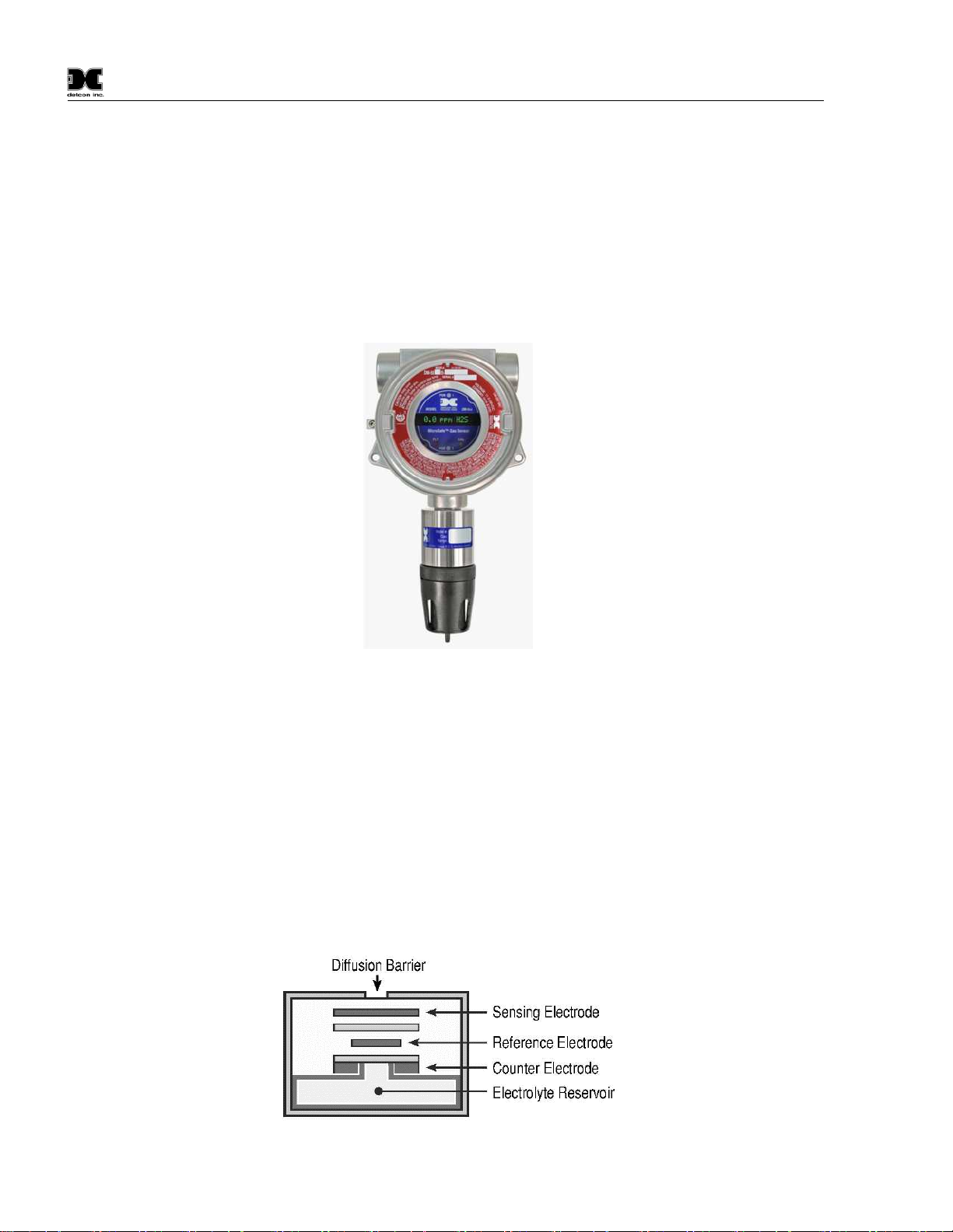
Figure 1 DM-500IS Sensor
Typical ranges of detection are 0-10ppm, 0-25ppm, 0-50ppm and 0-100ppm. Other ranges are available and all
ranges are covered by this manual. To determine sensor model number, reference the label located on the
enclosure cover. To determine gas type and range, reference labeling on the intrinsically safe sensor head.
1.1 Sensor Technology
The sensors are electrolytic chemical cells. Each cell consists of three electrodes embedded in an electrolyte
solution all housed beneath a diffusion membrane. Sensitivity to specific target gases is achieved by varying
composition of any combination of the sensor components. Good specificity is achieved in each sensor type.
The cells are diffusion limited via small capillary barriers resulting in long service life of up to 3 or more
years. The fuel cell is packaged as a field replaceable plug-in sensor via gold plated pins. Pre-amplifier and
intrinsically safe barrier circuits are epoxy potted in the stainless steel housing and include the mating sockets
for the sensor.
Figure 2 Construction of Electrochemical Sensor

DM-500IS
DM-500IS Instruction Manual Rev 0.1 Page 3 of 30
1.2 Universal Microprocessor Control Transmitter Circuit
The control circuit is microprocessor based and is packaged as a universal plug-in field replaceable module,
facilitating easy replacement and minimum down time. The universality includes the ability to set it for any
range concentration and for any gas type. These gas and range settings must be consistent with the IS Sensor
Head it is mated with. Circuit functions include a basic sensor pre-amplifier, on-board power supplies,
microprocessor, back lit alpha numeric display, fault and calibration status LED indicators, magnetic
programming switches, and a linear 4-20 mA DC output.
Figure 3 Universal Microprocessor Control Transmitter circuit
1.3 Base Connector Board
The base connector board is mounted in the explosion proof enclosure and includes: the mating connector for
the control circuit, reverse input and secondary transient suppression, input filter and lugless terminals for all
field wiring.
Figure 4 Base connector board
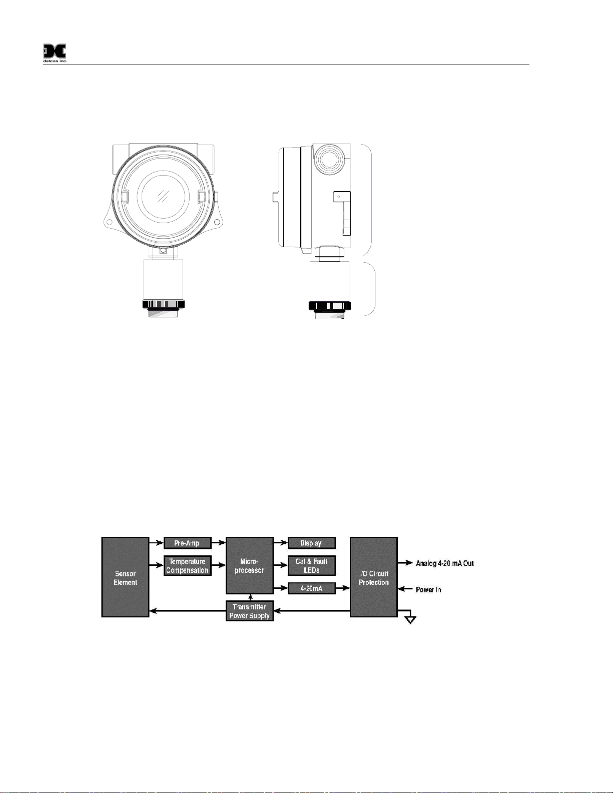
1.4 Explosion Proof Enclosure
The transmitter electronics are packaged in a cast metal explosion proof enclosure. The enclosure is fitted with
a threaded cover that has a glass lens window. Magnetic program switches located behind the transmitter
module face plate are activated through the lens window via a hand-held magnetic programming tool allowing
non-intrusive operator interface with the sensor. Calibration can be accomplished without removing the cover
or declassifying the area. Electrical classification is Class I; Groups B, C, D; Division 1 (explosion proof).
DM-500IS
DM-500IS Instruction Manual Rev 0.1 Page 4 of 30
The sensor housing section employs an Intrinsically Safe Barrier circuit which allows for the safe usage of
plastic housing materials in the lower section. This design benefit avoids the requirement for stainless steel
flame arrestors which reduce the sensitivity and response time to “active” gas species such as NH3, CL2,
CLO2, and HCL...etc.
Transmitter Electronics in
Explosion-Proof Housing
Intrinsically Safe
Sensor Head
Figure 5 Explosion-Proof Enclosure
2.0 Principle Of Operation
Method of detection is by an electrochemical reaction at the surface of an electrode called the sensing
electrode. Air and gas diffuse through the capillary diffusion barrier. The controlling circuit maintains a small
external operating voltage between the sensing and counter electrodes of the proper bias and magnitude so that
no current flows to or from the reference electrode while its potential is maintained at the correct fixed voltage
- usually ground. The electrochemical reaction creates a change in current flow from the counter electrode to
the sensing electrode. This change in current is proportional to the gas concentration and is reversible. The
quick response of the sensor results in continuous monitoring of ambient air conditions. The Intrinsically Safe
Sensor Housing design allows direct contact of the target gas to the electrochemical sensor, thus maximizing
response time, detectability and repeatability.
Figure 6 Functional Block Diagram

DM-500IS
DM-500IS Instruction Manual Rev 0.1 Page 5 of 30
3.0 Application
3.1 Sensor Placement/Mounting
Sensor location should be reviewed by facility engineering and safety personnel. Area leak sources and
perimeter mounting are typically used to determine number and location of sensors. The sensors are generally
located 2 - 4 feet above grade.
3.2 Interference Data
Detcon Model DM-500IS series electrochemical sensors are subject to interference from other gases. This
interaction is shown in the table in section 3.4 as the relation between the amount of the interfering gas applied
to the sensor, and the corresponding reading that will occur. All measurements are in ppm unless otherwise
noted.
The table is laid out with the Model Number of each sensor in a column on the left side of the page. The
interfering gases are listed in a row across the top of the page. Each page lists all Model Numbers but 5 pages
are necessary to list all interfering gases, thus each page is a repeat of the full line of Detcon sensors. Be sure
to reference each page to ascertain the full listing of interfering gases for a particular sensor.
As an example, the first listing shows that the Model DM-500IS-C2H30 acetaldehyde sensor will have an
interference reading of 340 ppm if 40 ppm of C2H2 (Acetylene) is applied.
NOTE
: Interference factors may differ from sensor to sensor and with life time. It is not
advisable to calibrate with interference gases. They should be used as a guide only

DM-500IS
DM-500IS Instruction Manual Rev 0.1 Page 6 of 30
3.3 Interference Gas List
Gas Name
Symbol
Gas Name
Symbol
Acetaldehyde C2H3O Hydrocarbons C-H’s
Acetylene C2H2 Hydrocarbons (unsaturated) C-H’s (u)
Acrylonitrile C3H3N Hydrogen H2
Alcohols Alcohols Hydrogen Bromide HBr
Amines Amines Hydrogen Chloride HCL
Ammonia NH3 Hydrogen Cyanide HCN
Arsenic Trifluoride AsF3 Hydrogen Fluoride HF
Arsenic Pentafluoride AsF5 Hydrogen Selenide HSe
Arsine AsH3 Hydrogen Sulfide H2S
Boron Trifluoride BF3 Iodine I2
Bromine Br2 Isopropanol C3H8O
Butadiene C4H6 Methane CH4
Buten-1 Buten-1 Methanol CH3OH
Carbon Dioxide CO2 Methyl-Ethyl-Ketone C4H8O
Carbon Disulfide CS2 Methyl Mercaptan CH3SH
Carbon Oxide Sulfide COS Nitric Oxide NO
Carbon Monoxide CO Nitrogen N2
Carbonyl Sulfide COS Nitrogen Dioxide NO2
Chlorine CL2 Ozone O3
Chlorine Dioxide CLO2 Phosgene COCL2
Chlorine Trifluoride CLF3 Phosphine PH3
Diborane B2H6 Phosphorous Trifluoride PF3
Dimethyl Sulfide C2H6S Silane SiH4
Disilane Si2H6 Silicon Si
Epichlorohydrin C3H5OCL Silicon Tetra Fluoride SiF4
Ethanol C2H5OH Sulfur Dioxide SO2
Ethyl Mercaptan C2H5SH Tetrahydrothiophene C4H8S
Ethylene C2H4 Thiophane C4H4S
Ethylene Oxide C2H4O Toluene C6H5CH3
Fluorine F2 Tungsten Hexafluoride WF6
Formaldehyde CH2O Vinyl Acetate C4H6O2
Germane GeH4 Vinyl Chloride C2H3CL
Hydrazine N2H4

DM-500IS
DM-500IS Instruction Manual Rev 0.1 Page 7 of 30
3.4 Interference Gas Table (page 1 of 5)
NOTE: Reference the listing in Table 1 to match model number with gas name. Reference the listing in section
3.3 to match the interfering gas symbol with the gas name.
n/a = not applicable
n/d = no data
Model Number C2H30 C2H2 C3H3N Alcohols Amines NH3 AsF3 AsF5 AsH3 BF3 Br2 C4H6 Buten-1
DM-500IS-C2H3O n/a 40=340 40=75 n/d n/d n/d n/d n/d n/d n/d n/d 40=170 n/d
DM-500IS-C2H2 340=40 n/a 340=75 n/d n/d n/d n/d n/d n/d n/d n/d 340=170 n/d
DM
-
500IS
-
C3H3N
75=40 75=340 n/d n/d n/d n/d n/d n/d n/d n/d n/d 75=170 n/d
DM
-
500IS
-
NH3
(
-
20°C)
n/d n/d n/d 1000=0 yes n/d n/a n/d n/d 1=0 n/d n/d n/d n/d
DM
-
501IS
-
NH3
(
-
40°C)
n/d n/d n/d n/d yes n/d n/d n/d n/d 1=0 n/d n/d n/d n/d
DM
-
502IS
-
NH3 (CE)
n/d n/d n/d n/d n/d n/d n/d n/d n/a n/d n/d n/d n/d
DM
-
500IS
-
AsH3
n/d n/d n/d n/d n/d 100=0.01 n/d n/a n/d n/d n/d n/d n/d
DM
-
500IS
-
Br2
n/d n/d n/d n/d n/d n/d n/d n/d n/d n/d n/a n/d n/d
DM
-
500IS
-
C4H6
170=40 170=340 170=75 n/d n/d n/d n/d n/d n/d n/d n/d n/a n/d
DM
-
500IS
-
CS2
140=40 140=340 140=75 n/d n/d n/d n/d n/d n/d n/d n/d 140=170 n/d
DM
-
500IS
-
CO
n/d n/d n/d n/d n/d n/d n/d n/d n/d n/d n/d n/d n/d
DM
-
500IS
-
COS
135=40 135=340 135=75 n/d n/d n/d n/d n/d n/d n/d n/d 135=170 n/d
DM
-
500IS
-
CL2
n/d n/d n/d n/d n/d n/d n/d n/d n/d n/d 1=0.55 n/d n/d
DM
-
500IS
-
CLO2 (>10ppm)
n/d n/d n/d n/d n/d n/d n/d n/d n/d n/d 1=0.18 n/d n/d
DM
-
501IS
-
CLO2 (
≤
10ppm)
n/d n/d n/d n/d n/d n/d n/d n/d n/d n/d n/d n/d n/d
DM
-
500IS
-
B2H6
n/d n/d n/d n/d n/d 100=0.013 n/d n/d 0.15=0.2 n/d n/d n/d n/d
DM
-
500IS
-
C2H6S
150=40 150=340 150=75 n/d n/d n/d n/d n/d n/d n/d n/d 150=170 n/d
DM
-
500IS
-
C3H5OCL
50=40 50=340 50=75 n/d n/d n/d n/d n/d n/d n/d n/d 50=170 n/d
DM
-
500IS
-
C2H5OH
180=40 180=340 180=75 n/d n/d n/d n/d n/d n/d n/d n/d 180=170 n/d
DM
-
500IS
-
C2H5SH
n/d n/d n/d n/d n/d n/d n/d n/d n/d n/d n/d n/d n/d
DM
-
500IS
-
C2H4
220=40 220=340 220=75 n/d n/d n/d n/d n/d n/d n/d n/d 220=170 n/d
DM
-
500IS
-
C2H4O
275=40 275=40 275=75 n/d n/d n/d n/d n/d n/d n/d n/d 275=170 n/d
DM
-
500IS
-
F2
n/d n/d n/d 1000=0 n/d n/d n/d n/d 0.1=0 n/d yes n/d n/d n/d
DM
-
500IS
-
CH2O
330=40 330=340 330=75 n/d n/d n/d n/d n/d n/d n/d n/d 330=170 n/d
DM
-
500IS
-
GeH4
n/d n/d n/d n/d n/d 100=<1 n/d n/d 0.2=0.14 n/d n/d n/d n/d
DM
-
500IS
-
N2H4
n/d n/d n/d 1000=0 n/d
200=0.04
n/d
n/d 0.1=0.1 n/d n/d n/d n/d
DM
-
500IS
-
H2 (ppm
)
n/d n/d n/d n/d n/d
n/d
n/d
n/d n/d n/d n/d n/d n/d
DM
-
501IS
-
H2 (LEL)
n/d n/d n/d n/d n/d
100=0
n/d
n/d n/d n/d n/d n/d n/d
DM
-
500IS
-
HBr
n/d n/d n/d 1000=0 No
n/d
n/d
n/d 0.1=0.3 n/d n/d n/d n/d
DM
-
500IS
-
HCL
n/d n/d n/d 1000=0 No
n/d
n/d
n/d 0.1=0.3 n/d n/d n/d n/d
DM
-
500IS
-
HCN
n/d n/d n/d 1000=0 n/d
n/d
n/d
n/d 0.1=0 n/d yes n/d n/d n/d
DM
-
500IS
-
H
F
n/d n/d n/d 1000=0 n/d
n/d
yes
n/d
yes n/d 0.1=0 yes n/d n/d n/d n/d
DM
-
500IS
-
H2S
n/d n/d n/d n/d n/d
n/d
n/d
n/d n/d n/d n/d n/d n/d
DM
-
500IS
-
CH3OH
415=40 415=340 415=75 n/d n/d
n/d
n/d
n/d n/d n/d n/d 415=170 n/d
DM
-
500IS
-
CH3SH
n/d n/d n/d n/d n/d
n/d
n/d
n/d n/d n/d n/d 275=170 n/d
DM
-
500IS
-
NO
n/d n/d n/d n/d n/d
n/d
n/d
n/d n/d n/d n/d n/d n/d
DM
-
500IS
-
NO2
n/d n/d n/d n/d n/d
n/d
n/d
n/d n/d n/d n/d n/d n/d
DM
-
500IS
-
O3
n/d n/d n/d n/d n/d
n/d
n/d
n/d 0.1=0.05 n/d yes n/d n/d n/d
DM
-
500IS
-
COCL2
n/d n/d n/d 1000=0 n/d
50=0.5
n/d
n/d n/d n/d n/d n/d n/d
DM
-
500IS
-
PH3
n/d n/d n/d n/d n/d
100=0.01
n/d
n/d 1=1 n/d n/d n/d n/d
DM
-
500IS
-
SiH4
n/d n/d n/d n/d n/d
100=<1
n/d
n/d 0.2=0.14 n/d n/d n/d n/d
DM
-
500IS
-
SO2
n/d n/d n/d n/d n/d
n/d
n/d
n/d n/d n/d n/d n/d n/d
DM
-
500IS
-
C4H8S
n/d n/d n/d n/d n/d
n/d
n/d
n/d n/d n/d n/d n/d n/d
DM
-
500IS
-
C4H4S
45=40 45=340 45=75 n/d n/d
n/d
n/d
n/d n/d n/d n/d 45=170 1%=1.8
DM
-
500IS
-
C6H5CH3
55=40 55=340 55=75 n/d n/d
n/d
n/d
n/d n/d n/d n/d 55=170 n/d
DM
-
500IS
-
C4H6O2
200=40 200=340 200=75 n/d n/d
n/d
n/d
n/d n/d n/d n/d 200=170 n/d
DM
-
500IS
-
C2H3CL
200=40 200=340 200=75 n/d n/d
n/d
n/d
n/d n/d n/d n/d 200=170 n/d

DM-500IS
DM-500IS Instruction Manual Rev 0.1 Page 8 of 30
Interference Gas Table (page 2 of 5)
n/a = not applicable
n/d = no data
Model Number CO2 CS2 CO COS CL2 CL02 CLF3 B2H6 C2H6S Si2H6 C3H5OCL C2H5OH
DM-500IS-C2H3O n/d 40=140 40=100 40=135 n/d n/d n/d n/d 40=150 n/d 40=50 40=180
DM-500IS-C2H2 n/d 340=140 340=100 340=135 n/d n/d n/d n/d 340=150 n/d 340=50 340=180
DM
-
500IS
-
C3H3N
n/d 75=140 75=100 75=135 n/d n/d n/d n/d 75=150 n/d 75=50 75=180
DM
-
500IS
-
NH3
(
-
20°C)
5000=0 n/d 1000=0 n/d 1=0 n/d n/d 0.1=0 n/d n/d n/d n/d
DM
-
501IS
-
NH3
(
-
40°C)
5000=0 n/d 300=100 n/d 5=0 n/d n/d 0.1=0 n/d n/d n/d n/d
DM
-
502IS
-
NH3 (CE)
n/d n/d 300=8 n/d 1=1 10%=15 n/d n/d n/d n/d n/d n/d
DM
-
500IS
-
AsH3
5000=0 n/d 300=0 n/d 0.5 = -0.04 n/d n/d 0.2=0.15 n/d 5=yes n/d n/d n/d
DM
-
500IS
-
Br2
n/d n/d 300=0 n/d 1=2 1=6 n/d n/d n/d n/d n/a n/d
DM
-
500IS
-
C4H6
n/d 170=140 170=100 170=135 n/d n/d n/d n/d 170=150 n/d 170=50 170=180
DM
-
500IS
-
CS2
n/d n/a 140=100 140=135 n/d n/d n/d n/d 140=150 n/d 140=50 140=180
DM
-
500IS
-
CO
n/d n/d n/a n/d 1=0 n/d n/d n/d n/d n/d n/d 200=0
DM
-
500IS
-
COS
n/d 135=140 135=100 n/a n/d n/d n/d n/d 135=150 n/d 135=50 135=180
DM
-
500IS
-
CL2
n/d n/d 300=0 n/d n/a n/d n/d n/d n/d n/d n/d n/d
DM
-
500IS
-
CLO2 (>10ppm)
n/d n/d 300=0 n/d 3=1 n/a n/d n/d n/d n/d n/d n/d
DM
-
501IS
-
CLO2 (
≤
10ppm)
5000=0 n/d 1000=0 n/d 1=0.9 n/a yes n/d 0.1=0 n/d n/d n/d n/d
DM
-
500IS
-
B2H6
5000=0 n/d 300=0 n/d 0.5 = -0.06 n/d n/d n/a n/d 5=yes n/d n/d n/d
DM
-
500IS
-
C2H6S
n/d 150=140 150=100 150=135 n/d n/d n/d n/d n/a n/d 150=50 150=180
DM
-
500IS
-
C3H5OCL
n/d 50=140 50=100 50=135 n/d n/d n/d n/d 50=150 n/d n/a 50=180
DM
-
500IS
-
C2H5OH
n/d 180=140 180=100 180=135 n/d n/d n/d n/d 180=150 n/d 180=50 n/a
DM
-
500IS
-
C2H5SH
n/d n/d 300≤5 n/d 1 = -0.6 n/d n/d n/d n/d n/d n/d n/d
DM
-
500IS
-
C2H4
n/d 220=140 220=100 220=135 n/d n/d n/d n/d 220=150 n/d 220=50 220=180
DM
-
500IS
-
C2H4O
n/d 275=100 275=100 275=135 n/d n/d n/d n/d 275=150 n/d 275=50 275=180
DM
-
500IS
-
F2
5000=0 n/d 1000=0 n/d 1=1.3 n/d n/d n/d n/d n/d n/d n/d
DM
-
500IS
-
CH2O
n/d 330=140 330=100 330=135 n/d n/d n/d n/d 330=150 n/d 330=50 330=180
DM
-
500IS
-
GeH4
5000=0 n/d 300=0 n/d 0.5 = -0.04 n/d n/d 0.2=0.11 n/d 5=yes n/d n/d n/d
DM
-
500IS
-
N2H4
5000=0 n/d 1000=0 n/d 1=0
n/d
n/d
n/d n/d n/d n/d n/d
DM
-
500IS
-
H2 (ppm
)
n/d n/d 300=<30 n/d 1=0
n/d
n/d
n/d n/d n/d n/d n/d
DM
-
501IS
-
H2 (LEL)
1000-0 n/d 50=6 n/d 5=0
n/d
n/d
n/d n/d n/d n/d n/d
DM
-
500IS
-
HBr
5000=0 n/d 1000=0 n/d 5=1
n/d
yes n
/d
n/d n/d n/d n/d n/d
DM
-
500IS
-
HCL
5000=0 n/d 1000=0 n/d 5=1
n/d
1=yes n/d
n/d n/d n/d n/d n/d
DM
-
500IS
-
HCN
5000=0 n/d 1000=0 n/d 5 = -1
n/d
n/d
n/d n/d n/d n/d n/d
DM
-
500IS
-
H
F
5000=0 n/d 1000=0 n/d 1=0.4
n/d
yes
n/d
0.1=0 n/d n/d n/d n/d
DM
-
500IS
-
H2S
n/d n/d 300=≤1.5 n/d 1 = ≈ -0.2
n/d
n/d
n/d n/d n/d n/d n/d
DM
-
500IS
-
CH3OH
n/d 415=140 415=100 415=135 n/d
n/d
n/d
n/d 415=150 n/d 415=50 415=180
DM
-
500IS
-
CH3SH
n/d n/d 300 ≤ 3 n/d 1 = --0.4
n/d
n/d
n/d n/d n/d n/d n/d
DM
-
500IS
-
NO
n/d n/d 300=0 n/d 1=0
n/d
n/d
n/d n/d n/d n/d n/d
DM
-
500IS
-
NO2
n/d n/d 300=0 n/d 1= ≈1
n/d
n/d
n/d n/d n/d n/d n/d
DM
-
500IS
-
O3
5000=0 n/d 300=0 n/d 1=1.4
0.1=0.12
1=1(theor.)
n/d n/d n/d n/d n/d
DM
-
500IS
-
COCL2
5000=0 n/d 1000=0 n/d 1=0
n/d
n/d
n/d n/d n/d n/d n/d
DM
-
500IS
-
PH3
5000=0 n/d 300=0 n/d 0.5 = -0.04
n/d
n/d
0.2=0.15 n/d 5=yes n/d n/d n/d
DM
-
500IS
-
SiH4
5000=0 n/d
300=0
n/d 0.5 = -0.04
n/d
n/d
0.2=0.11 n/d 5=yes n/d n/d n/d
DM
-
500IS
-
SO2
n/d n/d
300=
<5
n/d 1=<0.5
n/d
n/d
n/d n/d n/d n/d n/d
DM
-
500IS
-
C4H8S
5000=0 n/d 0.1%=1.2 1%=10 n/d
n/d
n/d
n/d n/d n/d n/d n/d
DM
-
500IS
-
C4H4S
n/d 45=140 45=100 45=135 n/d
n/d
n/d
n/d 45=150 n/d 45=50 45=180
DM
-
500IS
-
C6H5CH3
n/d 55=140 55=100 55=135 n/d
n/d
n/d
n/d 55=150 n/d 55=50 55=180
DM
-
500IS
-
C4H6O2
n/d 200=140 200=100 200=135 n/d
n/d
n/d
n/d 200=150 n/d 200=50 200=180
DM
-
500IS
-
C2H3CL
n/d 200=140 200=100 200=135 n/d
n/d
n/d
n/d 200=150 n/d 200=50 200=180

DM-500IS
DM-500IS Instruction Manual Rev 0.1 Page 9 of 30
Interference Gas Table (page 3 of 5)
n/a = not applicable
n/d = no data
Model Number C2H4 C2H4O F2 CH2O GeH4 N2H4 C-H’s C-H’s (U) H2 HBr HCL HCN HF
DM-500IS-C2H3O 40=220 40=275 n/d 40=330 n/d n/d n/d n/d n/d n/d n/d n/d n/d
DM-500IS-C2H2 340=220 340=275 n/d 340=330 n/d n/d n/d n/d n/d n/d n/d n/d n/d
DM
-
500IS
-
C3H3N
75=220 75=275 n/d 75=330 n/d n/d n/d n/d n/d n/d n/d n/d n/d
DM
-
500IS
-
NH3
(
-
20°C)
n/d n/d n/d n/d 1=0 n/d %range=0
n/d
1%=0 n/d 5=0 10=0 4=0
DM
-
501IS
-
NH3
(
-
40°C)
n/d n/d n/d n/d 1=0 n/d %range=0
yes
n/d
1000=35 n/d yes n/d 10 = -18 n/d
DM
-
502IS
-
NH3 (CE)
100=0 n/d n/d n/d n/d n/d n/d n/d 200=4 n/d 5 = -3 10=0 n/d
DM
-
500IS
-
AsH3
n/d n/d n/d n/d 1=0.4 n/d %range=0 n/d 3000=0 n/d
5=0
10=0.1 4=0
DM
-
500IS
-
Br2
100=0 n/d n/d n/d n/d n/d n/d n/d 100=0 n/d
5=0
10=0 n/d
DM
-
500IS
-
C4H6
170=220 170=275 n/d 170=330 n/d n/d n/d n/d n/d n/d n/d n/d n/d
DM
-
500IS
-
CS2
140=220 140=275 n/d 140=330 n/d n/d n/d n/d n/d n/d n/d n/d n/d
DM
-
500IS
-
CO
100=<100 n/d n/d n/d n/d n/d n/d n/d 100 = <60 n/d 5=0 10 = -2 n/d
DM
-
500IS
-
COS
135=220 135=275 n/d 135=330 n/d n/d n/d n/d n/d n/d n/d n/d n/d
DM
-
500IS
-
CL2
100=0 n/d n/d n/d n/d n/d n/d n/d 100=0 n/d
5=0
10=0
n/d
DM
-
500IS
-
CLO2 (>10ppm)
100=0 n/d n/d n/d n/d n/d n/d n/d 100=0 n/d
5=0
10=0
n/d
DM
-
501IS
-
CLO2 (
≤
10ppm)
n/d n/d yes n/d n/d 1=0 n/d %range=0
n/d
1%=0 n/d n/d n/d n/d
DM
-
500IS
-
B2H6
n/d n/d n/d n/d 1=0.53 n/d %range=0
n/d
3000=0 n/d 5=0 10=0.13 4=0
DM
-
500IS
-
C2H6S
150=220 150=275 n/d 150=330 n/d n/d n/d n/d n/d n/d n/d n/d n/d
DM
-
500IS
-
C3H5OCL
50=220 50=275 n/d 50=330 n/d n/d n/d n/d n/d n/d n/d n/d n/d
DM
-
500IS
-
C2H5OH
180=220 180=275 n/d 180=330 n/d n/d n/d n/d n/d n/d n/d n/d n/d
DM
-
500IS
-
C2H5SH
100=0 n/d n/d n/d n/d n/d n/d n/d 1%=<15 n/d 5=0 10=0 n/d
DM
-
500IS
-
C2H4
n/a 220=275 n/d 220=330 n/d n/d n/d n/d n/d n/d n/d n/d n/d
DM
-
500IS
-
C2H4O
275=200 n/a n/d 275=330 n/d n/d n/d n/d n/d n/d n/d n/d n/d
DM
-
500IS
-
F2
n/d n/d n/a n/d n/d n/d %range=0
n/d
1%=0 n/d 5=0 1 = -3 3=0
DM
-
500IS
-
CH2O
330=220 330=275 n/d n/a n/d n/d n/d
n/d
n/d n/d n/d n/d n/d
DM
-
500IS
-
GeH4
n/d n/d n/d n/d n/a n/d %range=0
n/d
3000=0 n/d
5=0
10=1 4=0
DM
-
500IS
-
N2H4
n/d n/d n/d n/d n/d
n/d
%range=0
n/d
1000=0 n/d
5=0
.1
n/d 3=0
DM
-
500IS
-
H2 (ppm
)
100= ≈80 n/d n/d n/d n/d
n/d
n/d
n/d
n/a n/d
5=0
10 = ≈3 n/d
DM
-
501IS
-
H2 (LEL)
yes n/d n/d n/d n/d n/d
n/d
n/d
n/d
n/a n/d n/d 10=0 n/d
DM
-
500IS
-
HBr
n/d n/d n/d n/d n/d
n/d
%range=0
n/d
1%=0
n/a 1=1
1
5
=
1
3=0
DM
-
500IS
-
HCL
n/d n/d n/d n/d 1=n/d
n/d
%range=0
n/d
1%=0
1=1 n/a
1
5
=
1
3=0
DM
-
500IS
-
HCN
n/d n/d n/d n/d n/d
n/d
%range=0
n/d
1
000
=0
n/d
5=0
n/a 3=0
DM
-
500IS
-
H
F
n/d n/d yes n/d n/d 1=0
n/d
%range=0
n/d
1%=0 n/d
5=
3.3
n/d n/a
DM
-
500IS
-
H2S
100=0 n/d n/d n/d n/d
n/d
n/d
n/d
1%=<5 n/d
5=0
10=0 n/d
DM
-
500IS
-
CH3OH
415=220 415=275 n/d 415=330 n/d
n/d
n/d
n/d
n/d n/d n/d n/d n/d
DM
-
500IS
-
CH3SH
100=0 n/d n/d n/d n/d
n/d
n/d
n/d
1%=<10 n/d
5=0
10=0
n/d
DM
-
500IS
-
NO
100=0 n/d n/d n/d n/d
n/d
n/d
n/d
100=0 n/d
5=
<1
10=0
n/d
DM
-
500IS
-
NO2
100=0 n/d n/d n/d n/d
n/d
n/d
n/d
100=0 n/d
5=0
10=0
n/d
DM
-
500IS
-
O3
n/d n/d 0.1=0.07 n/d n/d
n/d
n/d
n/d
1%=0.003 n/d
10
=0
10=0.33 5=0
DM
-
500IS
-
COCL2
n/d n/d n/d n/d n/d
n/d
%range=0
n/d
1%=0 n/d
5=0
5=0 3=0
DM
-
500IS
-
PH3
n/d n/d n/d n/d 1=0.4
n/d
%range=0
n/d
3000=0 n/d
5=0
10=0
.1
4=0
DM
-
500IS
-
SiH4
n/d n/d n/d n/d 1=1.0
n/d
%range=0
n/d
3000=0 n/d
5=0
10=
1
4=0
DM
-
500IS
-
SO2
100=0 n/d n/d n/d n/d
n/d
n/d
n/d
100=0 n/d
5=0
10=
<5
n/d
DM
-
500IS
-
C4H8S
1%=2.4 n/d n/d n/d n/d
n/d
%range=0
yes
n/d
0.1%=0.3 n/d yes n/d n/d n/d
DM
-
500IS
-
C4H4S
45=220 45=275 n/d 45=330 n/d
n/d
n/d
n/d
n/d n/d n/d n/d n/d
DM
-
500IS
-
C6H5CH3
55=220 55=275 n/d 55=330 n/d
n/d
n/d
n/d
n/d n/d n/d n/d n/d
DM
-
500IS
-
C4H6O2
200=220 200=275 n/d 200=330 n/d
n/d
n/d
n/d
n/d n/d n/d n/d n/d
DM
-
500IS
-
C2H3CL
200=220 200=275 n/d 200=330 n/d
n/d
n/d
n/d
n/d n/d n/d n/d n/d

DM-500IS
DM-500IS Instruction Manual Rev 0.1 Page 10 of 30
Interference Gas Table (page 4 of 5)
n/a = not applicable
n/d = no data
Model Number HSe H2S I2 C3H8O CH4 CH3OH C4H8O CH3SH NO N2 NO2 03 COCL2
DM-500IS-C2H3O n/d n/d n/d n/d n/d 40=415 n/d 40=275 n/d n/d n/d n/d n/d
DM-500IS-C2H2 n/d n/d n/d n/d n/d 340=415 n/d 340=275 n/d n/d n/d n/d n/d
DM
-
500IS
-
C3H3N
n/d n/d n/d n/d n/d 75=415 n/d 75=275 n/d n/d n/d n/d n/d
DM
-
500IS
-
NH3
(
-
20°C)
0.1=0 10=0 n/d n/d n/d n/a n/d n/d n/d 100%=0 n/d n/d n/d
DM
-
501IS
-
NH3
(
-
40°C)
n/d 14=18 n/d n/d n/d yes n/d n/d n/d n/d 100%=0 10 = -5 n/d n/d
DM
-
502IS
-
NH3 (CE)
n/d 15=30 n/d n/d n/d n/d n/d n/d 35=6 n/d 5 = -1 n/d n/d
DM
-
500IS
-
AsH3
0.05=0.005 1=0 n/d n/d n/d n/d n/d n/d n/d 100%=0 n/d n/d n/d
DM
-
500IS
-
Br2
n/d 15 = -1.5 n/d n/d n/d n/d n/d n/d 35=0 n/d 5 = ≈10 n/d n/d
DM
-
500IS
-
C4H6
n/d n/d n/d n/d n/d 170=415 n/d
170
=275
n/d n/d n/d n/d n/d
DM
-
500IS
-
CS2
n/d n/d n/d n/d n/d 140=415 n/d
140
=275
n/d n/d n/d n/d n/d
DM
-
500IS
-
CO
n/d 15=<0.3 n/d n/d n/d n/d n/d n/d 35=≤7 n/d n/d n/d n/d
DM
-
500IS
-
COS
n/d n/d n/d n/d n/d 135=415 n/d 135=275 n/d n/d n/d n/d n/d
DM
-
500IS
-
CL2
n/d
15
=
-
0.75
n/d n/d n/d n/d n/d n/d
35=
0
n/d 5 = ≈5 n/d n/d
DM
-
500IS
-
CLO2 (>
10ppm)
n/d
15=
0.25
n/d n/d n/d n/d n/d n/d 35=0 n/d 5=1.66 n/d n/d
DM
-
501IS
-
CLO2 (
≤
10ppm)
n/d 10 = -0.015 n/d n/d n/d n/d n/d n/d n/d n/d yes n/d yes n/d n/d
DM
-
500IS
-
B2H6
0.05=0.006 1=0 n/d n/d n/d n/d n/d n/d n/d 100%=0 n/d n/d n/d
DM
-
500IS
-
C2H6S
n/d n/d n/d n/d n/d
150
=415
n/d 1:15 n/d n/d n/d n/d n/d
DM
-
500IS
-
C3H5OCL
n/d n/d n/d n/d n/d
50
=415
n/d
50
=275
n/d n/d n/d n/d n/d
DM
-
500IS
-
C2H5OH
n/d n/d n/d n/d n/d
180
=415
n/d
180
=275
n/d n/d n/d n/d n/d
DM
-
500IS
-
C2H5SH
n/d 1:3 n/d n/d n/d
n/d
n/d 5=8 35=<6 n/d 5 = -1.5 n/d n/d
DM
-
500IS
-
C2H4
n/d n/d n/d n/d n/d
220
=415
n/d
220
=275
n/d n/d n/d n/d n/d
DM
-
500IS
-
C2H4O
n/d n/d n/d n/d n/d
275
=415
n/d
275
=275
n/d n/d n/d n/d n/d
DM
-
500IS
-
F2
n/d 1 = -1.5 n/d n/d n/d
n/d
n/d n/d n/d 100%=0 1=0.05 0.1=0.2 n/d
DM
-
500IS
-
CH2O
n/d n/d n/d n/d n/d
330
=415
n/d 330=275 n/d n/d n/d n/d n/d
DM
-
500IS
-
GeH4
0.05=0.005
1=0
n/d n/d n/d n/d n/d n/d n/d
100%=0
n/d n/d n/d
DM
-
500IS
-
N2H4
n/d
1=0
.1
n/d n/d n/d n/d
n/d
n/d n/d
100%=0
1 = -0.25 0.1 = -0.1 n/d
DM
-
500IS
-
H2 (ppm
)
n/d
1
5
=
<3
n/d n/d n/d n/d
n/d
n/d 35= ≈10 n/d 5=0 n/d n/d
DM
-
501IS
-
H2 (LEL)
n/d
n/d
n/d yes n/d 1%=0 n/d
n/d
n/d yes n/d n/d 10=0 n/d n/d
DM
-
500IS
-
HBr
0.1=0
1
0
=
2.75
n/d n/d n/d n/d
n/d
n/d n/d
100%=0
n/d n/d 0.1=0
DM
-
500IS
-
HCL
0.1=0
1
0
=
2.75
n/d n/d n/d n/d
n/d
n/d n/d
100%=0
n/d n/d 0.1=0
DM
-
500IS
-
HCN
n/d
1
0
=0
n/d n/d n/d n/d
n/d
n/d n/d
100%=0
10 = -12 0.1=0 n/d
DM
-
500IS
-
H
F
n/d
1
0
=0
n/d n/d n/d n/d
n/d
n/d n/d
100%=0
10=0.1 n/d n/d
DM
-
500IS
-
H2S
n/d n/a n/d n/d n/d n/d
n/d
2:1 35=<2 n/d 5 = -0.5 n/d n/d
DM
-
500IS
-
CH3OH
n/d n/d n/d n/d n/d n/d
n/d
415=275 n/d n/d n/d n/d n/d
DM
-
500IS
-
CH3SH
n/d 1:2 n/d n/d n/d n/d
n/d
n/a 35=<4 n/d
5 =
-
1.0
n/d n/d
DM
-
500IS
-
NO
n/d
1
5
=
≈5
n/d n/d n/d n/d
n/d
n/d 100=0 n/d
5
=<1.5
n/d n/d
DM
-
500IS
-
NO2
n/d
1
5
=
-
0.75
n/d n/d n/d n/d
n/d
n/d 35=0 n/d n/a n/d n/d
DM
-
500IS
-
O3
n/d
1
=
-
.015
yes n/d n/d n/d n/d
n/d
n/d 10=0
100%=0
1=0.7 n/a n/d
DM
-
500IS
-
COCL2
n/d
1=0
n/d n/d n/d n/d
n/d
n/d n/d
100%=0
n/d n/d n/a
DM
-
500IS
-
PH3
0.05=0.005
1=0
n/d n/d n/d n/d
n/d
n/d n/d
100%=0
n/d n/d n/d
DM
-
500IS
-
SiH4
0.05=0.005
1=0
n/d n/d n/d n/d
n/d
n/d
n/d
100%=0
n/d n/d n/d
DM
-
500IS
-
SO2
n/d
1
5
=0
n/d n/d n/d n/d
n/d
n/d
35=
0
n/d 5 = ≈ -5 n/d n/d
DM
-
500IS
-
C4H8S
n/d
20
=0
.3
n/d n/d 100%=0
1300
=
64
n/d
n/d
10
=
7.5
100%=0 10=0.9 n/d n/d
DM
-
500IS
-
C4H4S
n/d n/d n/d n/d n/d
45
=415
n/d
45
=
27
5
n/d n/d n/d n/d n/d
DM
-
500IS
-
C6H5CH3
n/d n/d n/d n/d n/d
55
=415
n/d
55
=
27
5
n/d n/d n/d n/d n/d
DM
-
500IS
-
C4H6O2
n/d n/d n/d n/d n/d
200
=415
n/d
200
=
27
5
n/d n/d n/d n/d n/d
DM
-
500IS
-
C2H3CL
n/d n/d n/d n/d n/d
200
=415
n/d
200
=
27
5
n/d n/d n/d n/d n/d

DM-500IS
DM-500IS Instruction Manual Rev 0.1 Page 11 of 30
Interference Gas Table (page 5 of 5)
n/a = not applicable
n/d = no data
Model Number PH3 PF3 SiH4 Si SiF4 SO2 C4H8S C4H4S C6H5CH3 WF6 C4H6O2 C2H3CL C2H5SH C6H5CH3
DM-500IS-C2H3O n/d n/d n/d n/d n/d n/d n/d 40=45 n/d n/d 40=200 40=200 n/d 40=55
DM-500IS-C2H2 n/d n/d n/d n/d n/d n/d n/d 340=45 n/d n/d 340=200 340=200 n/d 340=55
DM
-
500IS
-
C3H3N
n/d n/d n/d n/d n/d n/d n/d 75=45 n/d n/d 75=200 75=200 n/d 75=55
DM
-
500IS
-
NH3
(-20°C)
300=0 n/d n/d n/d n/d 2=0 n/d n/d n/d n/d n/d n/d n/d n/d
DM
-
501IS
-
NH3
(-40°C)
0.3=0 n/d n/d n/d n/d yes n/d n/d n/d n/d n/d n/d n/d n/d n/d
DM
-
502IS
-
NH3 (CE)
n/d n/d n/d n/d n/d 5= --0.5 n/d n/d n/d n/d n/d n/d n/d n/d
DM
-
500IS
-
AsH3
0.1-0.11 n/d 1=0.56 n/d n/d 2=0 n/d n/d n/d n/d n/d n/d n/d n/d
DM
-
500IS
-
Br2
n/d n/d n/d n/d n/d 5= -0.1 n/d n/d n/d n/d n/d n/d n/d n/d
DM
-
500IS
-
C4H6
n/d n/d n/d n/d n/d n/d n/d
17
0=45
n/d n/d 170=200 170=200 n/d
17
0=
55
DM
-
500IS
-
CS2
n/d n/d n/d n/d n/d n/d n/d
1
40=45
n/d n/d 140=200 140=200 n/d
1
40=
55
DM
-
500IS
-
CO
n/d n/d n/d n/d n/d 5=0 n/d n/d n/d n/d n/d n/d n/d n/d
DM
-
500IS
-
COS
n/d n/d n/d n/d n/d n/d n/d 135=45 n/d n/d 135=200 135=200 n/d 135=55
DM
-
500IS
-
CL2
n/d n/d n/d n/d n/d 5=-0.05 n/d n/d n/d n/d n/d n/d n/d n/d
DM
-
500IS
-
CLO2
(>10ppm)
n/d n/d n/d n/d n/d 5=-0.016 n/d n/d n/d n/d n/d n/d n/d n/d
DM
-
501IS
-
CLO2
(≤10ppm)
n/d n/d n/d n/d n/d n/d n/d n/d n/d n/d n/d n/d n/d n/d
DM
-
500IS
-
B2H6
0.1=0.14 n/d 1=0.72 n/d n/d 2=0 n/d n/d n/d n/d n/d n/d n/d n/d
DM
-
500IS
-
C2H6S
n/d n/d n/d n/d n/d n/d n/d
15
0=
45
n/d n/d 150=200 150=200 n/d
15
0=
55
DM
-
500IS
-
C3H5OCL
n/d n/d n/d n/d n/d n/d n/d
5
0=
45
n/d n/d 50=200 50=200 n/d
5
0=
55
DM
-
500IS
-
C2H5OH
n/d n/d n/d n/d n/d n/d n/d
18
0=
45
n/d n/d 180=200 180=200 n/d
18
0=
55
DM
-
500IS
-
C2H5SH
n/d n/d n/d n/d n/d 5=<3 n/d n/d n/d n/d n/d n/d n/d n/d
DM
-
500IS
-
C2H4
n/d n/d n/d n/d n/d n/d n/d
22
0=45
n/d n/d 220=200 220=200 n/d
22
0=
55
DM
-
500IS
-
C2H4O
n/d n/d n/d n/d n/d n/d n/d
275
=45
n/d n/d 275=200 275=200 n/d
275
=
55
DM
-
500IS
-
F2
n/d n/d n/d n/d n/d 2=0 n/d n/d n/d n/d n/d n/d n/d n/d
DM
-
500IS
-
CH2O
n/d n/d n/d n/d n/d n/d n/d 330=45 n/d n/d 330=200 330=200 n/d 330=55
DM
-
500IS
-
GeH4
0.1=0.13 n/d n/d n/d n/d 2=0 n/d n/d n/d n/d n/d n/d n/d n/d
DM
-
500IS
-
N2H4
0.3=0.1 n/d n/d n/d n/d
2=0
n/d
n/d
n/d n/d n/d n/d n/d
n/d
DM
-
500IS
-
H2 (ppm
)
n/d n/d n/d n/d n/d
5
=0
n/d
n/d
n/d n/d n/d n/d n/d
n/d
DM
-
501IS
-
H2 (LEL)
n/d n/d n/d n/d n/d
2=0
n/d
n/d
n/d n/d n/d n/d n/d
n/d
DM
-
500IS
-
HBr
0.1=0.3 n/d n/d n/d n/d
5
=
2.5
n/d
n/d
n/d n/d n/d n/d n/d
n/d
DM
-
500IS
-
HCL
0.1=0.3 n/d n/d n/d n/d
5
=
2.5
n/d
n/d
n/d n/d n/d n/d n/d
n/d
DM
-
500IS
-
HCN
0.3=0 n/d n/d n/d n/d
2=0
n/d
n/d
n/d n/d n/d n/d n/d
n/d
DM
-
500IS
-
H
F
0.1=0 yes n/d n/d n/d 3=4
(theor.)
yes
n/d
n/d
n/d
n/d yes n/d n/d n/d n/d
n/d
DM
-
500IS
-
H2S
n/d n/d n/d n/d n/d
5=<1
n/d
n/d
n/d n/d n/d n/d 3=1
n/d
DM
-
500IS
-
CH3OH
n/d n/d n/d n/d n/d
n/d
n/d
415=45
n/d n/d 415=200 415=200 n/d
415=55
DM
-
500IS
-
CH3SH
n/d n/d n/d n/d n/d
5
=
<2
n/d
n/d
n/d n/d n/d n/d 2=1
n/d
DM
-
500IS
-
NO
n/d n/d n/d n/d n/d
5
=0
n/d
n/d
n/d n/d n/d n/d n/d
n/d
DM
-
500IS
-
NO2
n/d n/d n/d n/d n/d
5
=
-
0.025
n/d
n/d
n/d n/d n/d n/d n/d
n/d
DM
-
500IS
-
O3
0.3=0.03 n/d 1=0.015 n/d n/d
2=0
n/d
n/d
n/d n/d n/d n/d n/d
n/d
DM
-
500IS
-
COCL2
0.3=0 n/d n/d n/d n/d
2=0
n/d
n/d
n/d n/d n/d n/d n/d
n/d
DM
-
500IS
-
PH3
n/a n/d 1=0.56 n/d n/d
2=0
n/d
n/d
n/d n/d n/d n/d n/d
n/d
DM
-
500IS
-
SiH4
0.1=0.13 n/a n/d n/d n/d
2=0
n/d
n/d
n/d n/d n/d n/d n/d
n/d
DM
-
500IS
-
SO2
n/d n/d n/d n/d n/d
n/
a
n/d
n/d
n/d n/d n/d n/d n/d
n/d
DM
-
500IS
-
C4H8S
n/d n/d n/d n/d n/d
2=0.6
n/a
n/
d
n/d n/d n/d n/d n/d
n/
a
DM
-
500IS
-
C4H4S
n/d n/d n/d n/d n/d
n/d
n/d
n/
a
n/d n/d 45=200 45=200 n/d
45
=
55
DM
-
500IS
-
C6H5CH3
n/d n/d n/d n/d n/d
n/d
n/d
55
=45
n/d n/d 55=200 n/d n/d
n/d
DM
-
500IS
-
C4H6O2
n/d n/d n/d n/d n/d
n/d
n/d
20
0=45
n/d n/d n/a 200=200 n/d
20
0=
55
DM
-
500IS
-
C2H3CL
n/d n/d n/d n/d n/d
n/d
n/d
20
0=45
n/d n/d 200=200 n/a n/d
20
0=
55

DM-500IS
DM-500IS Instruction Manual Rev 0.1 Page 12 of 30
4.0 Specifications
Method of Detection
Electrochemical Cell
Electrical Classification
CSA-NRTL (US OSHA) approved* Class 1; Groups B, C, D; Div. 1.
Input Voltage
11.5-28 VDC
Power Consumption
Normal operation = 29.5 mA @ 24VDC
Maximum 50mA @ 24VDC
Maximum 70mA @ 11.5VDC
Output
Linear 4-20 mA DC
Repeatability
± 2% FS
Table 2 Sensor cell specifications
Model Number
Gas Name
Response
Time(seconds)
Span Drift
Temperature
Range °C
Temperature
Range °F
Humidity
Range %
SensorCell
Warranty
DM
-
500IS
-
C2H3O
Acetaldehyde
T90 <140
<5%
signal loss/year
-
20 to +50
-
4 to +122
15 to 90
2 years
DM
-
500IS
-
C2H2
Acetylene
T90 <140
<5% signal loss/year
-
20 to +50
-
4 to +122
15 to 90
2 years
DM
-
500IS
-
C3H3N
Acrylonitrile
T90 <140
<5% signal loss/year
-
20 to +50
-
4 to +122
15 to 90
2 years
DM
-
500IS
-
NH3 (
-
20°C)
Ammonia
T90 <60
<1% signal loss/month
-
20 to +40
-
4 to +104
10 to 95
2 years
DM
-
501IS
-
NH3 (
-
40°C)
Ammonia
T90 <90
<2% signal loss/month
-
40 to +40
-
40 to +104
5 to 95
2 years
DM
-
502IS
-
NH3 (CE)
Ammonia
T90 <90
<2% signal loss/month
-
40 to +50
-
40 to +122
15 to 90
2 years
DM
-
500IS
-
AsH3
Arsine
T90 <60
<5% signal loss/month
-
20 to +40
-
4 to +104
20 to 95
11/2
years
DM
-
500IS
-
Br2
Bromine
T90 <60
<2% signal loss/month
-
20 to +50
-
4 to +122
15 to 90
2 years
DM
-
500IS
-
C4H6
Butadiene
T90 <
140
<5% signal loss/year
-
20 to +50
-
4 to +122
15 to 90
2 years
DM
-
500IS
-
CS2
Carbon Disulfide
T90 <140
<5% signal loss/year
-
20 to +50
-
4 to +122
15 to 90
2 years
DM
-
500IS
-
CO
Carbon Monoxide
T90
≤
30
<5% signal loss/year
-
40 to +50
-
40 to +122
15 to 90
3
years
DM
-
500IS
-
COS
Carbonyl Sulfide
T90 <140
<5% signal loss/year
-
20 to +50
-
4 to +122
15 to 90
2 years
DM
-
500IS
-
CL2
Chlorine
T90 <60
<2% signal loss/month
-
20 to +50
-
4 to +122
15 to 90
2 years
DM
-
500IS
-
CL
O
2
(>
10ppm
)
Chlorine Dioxide
T90 <60
<2%
signal loss/month
-
20 to +50
-
4 to +122
15 to 90
2 years
DM
-
50
1
IS
-
CL
O
2
(
≤
10
ppm)
Chlorine Dioxide
T90 <120
<1% signal loss/month
-
20 to +40
-
4 to +104
10 to 95
2 years
DM
-
500IS
-
B2H6
Diborane
T90 <60
<5% signal loss/month
-
20 to +40
-
4 to +104
20 to 95
1
-
1/2
years
DM
-
500IS
-
C2H6S
Dimethyl Sulfide
T90 <140
<5% signal loss/year
-
20 to +50
-
4 to +122
15 to 90
2 years
DM
-
500IS
-
C3H5OCL
Epichlorohydrin
T90 <140
<5% signal loss/year
-
20 to +50
-
4 to +122
15 to 90
2 years
DM
-
500IS
-
C2H5OH
Ethanol
T90 <140
<5%
signal loss/year
-
20 to +50
-
4 to +122
15 to 90
2 years
DM
-
500IS
-
C2H5SH
Ethyl Mercaptan
T90 <45
<2% signal loss/month
-
40 to +50
-
40 to +122
15 to 90
2 years
DM
-
500IS
-
C2H4
Ethylene
T90 <140
<5% signal loss/year
-
20 to +50
-
4 to +122
15 to 90
2 years
DM
-
500IS
-
C2H4O
Ethylene Oxide
T90 <140
<5% signal loss/year
-
20 to +50
-
4 to +122
15 to 90
2 years
DM
-
500IS
-
F2
Fluorine
T90 <80
<5% signal loss/year
-
10 to +40
+14 to +104
10 to 95
1
-
1/2
years
DM
-
500IS
-
CH2O
Formaldehyde
T90 <140
<5% signal loss/year
-
20
to +50
-
4 to +122
15 to 90
2 years
DM
-
500IS
-
GeH4
Germane
T90 <60
<1% signal loss/month
-
20 to +40
-
4 to +104
20 to 95
1
-
1/2
years
DM
-
500IS
-
N2H4
Hydrazine
T90 <120
<5% signal loss/month
-
10 to +40
+14 to +104
10 to 95
1 year
DM
-
500IS
-
H2 (ppm)
Hydrogen
T90
≤
30
<2% signal loss/month
-
20 to +50
-
4 to +122
15 to 90
2 years
DM
-
501IS
-
H2 (LEL)*
Hydrogen
T90 <60
<2% signal loss/month
-
40 to +40
-
40 to +104
5 to 95
2 years
DM
-
500IS
-
HBr
Hydrogen Bromide
T90 <70
<3% signal loss/month
-
20 to +40
-
4 to +104
10 to
95
1
-
1/2
years
DM
-
500IS
-
HCL
Hydrogen Chloride
T90 <70
<2% signal loss/month
-
20 to +40
-
4 to +104
10 to 95
1
-
1/2
years
DM
-
500IS
-
HCN
Hydrogen Cyanide
T90 <40
<5% signal loss/month
-
40 to +40
-
40 to +104
5 to 95
2 years
DM
-
500IS
-
HF
Hydrogen Fluoride
T90 <
90
<10%
signal loss/month
-
20 to +35
-
4 to +95
10 to 80
1
-
1/2
years
DM
-
500IS
-
H2S
Hydrogen Sulfide
T90
≤
30
<2% signal loss/month
-
40 to +50
-
40 to +122
15 to 90
2 years
DM
-
500IS
-
CH3OH
Methanol
T90 <140
<5% signal loss/year
-
20 to +50
-
4 to +122
15 to 90
2
years
DM
-
500IS
-
CH3SH
Methyl Mercaptan
T90 <45
<2% signal loss/month
-
40 to +50
-
40 to +122
15 to 90
2 years
DM
-
500IS
-
NO
Nitric Oxide
T90
≤
10
<2% signal loss/month
-
20 to +50
-
4 to +122
15 to 90
3 years
DM
-
500IS
-
NO2
Nitrogen Dioxide
T90 <40
<2% signal
loss/month
-
20 to +50
-
4 to +122
15 to 90
2 years
DM
-
500IS
-
O3
Ozone
T90 <120
<1% signal loss/month
-
10 to +40
+14 to +104
10 to 95
2 years
DM
-
500IS
-
COCL2
Phosgene
T90 <120
<1% signal loss/month
-
20 to +40
-
4 to +104
10 to 95
1
-
1/2
years
DM
-
500IS
-
PH3
Phosphine
T90 <30
<1% signal loss/month
-
20 to +40
-
4 to +104
20 to 95
1
-
1/2
years
DM
-
500IS
-
SiH4
Silane
T90 <60
<1% signal loss/month
-
20 to +40
-
4 to +104
20 to 95
1
-
1/2
years

DM-500IS
DM-500IS Instruction Manual Rev 0.1 Page 13 of 30
DM
-
500IS
-
SO2
Sulfur Dioxide
T90
≤
20
<2% signal loss/month
-
20 to +50
-
4 to
+122
15 to 90
2 years
DM
-
500IS
-
C4H8S
Tetrahydrothiophene
T90 <30
<2% signal loss/month
-
10 to +40
+14 to +104
10 to 95
2 years
DM
-
500IS
-
C4H4S
Thiophane
T90 <140
<5% signal loss/year
-
20 to +50
-
4 to +122
15 to 90
2 years
DM
-
500IS
-
C6H5CH3
Toluene
T90 <
140
<5% signal loss/year
-
20 to +50
-
4 to +122
15 to 90
2 years
DM
-
500IS
-
C4H6O2
Vinyl Acetate
T90 <140
<5% signal loss/year
-
20 to +50
-
4 to +122
15 to 90
2 years
DM
-
500IS
-
C2H3CL
Vinyl Chloride
T90 <140
<5% signal loss/year
-
20 to +50
-
4 to +122
15 to 90
2 years
*LELrangeH2isnotCSAapproved.
5.0 Installation
Optimum performance of ambient air/gas sensor devices is directly relative to proper location and installation
practice.
5.1 Field Wiring Table (4-20 mA output)
Detcon Model DM-500IS toxic gas sensor assemblies require three conductor connection between power
supplies and host electronic controllers. Wiring designators are +(DC), –(DC), and mA (sensor signal).
Maximum single conductor resistance between sensor and controller is 10 ohms. Maximum wire size for
termination in the sensor assembly terminal board is 14 gauge.
AWG Meters Feet
18 360 1200
16 600 2000
14 900 3000
Table 3 Field wiring Table
Note
1
: This wiring table is based on stranded tinned copper wire and is designed to serve as a
reference only.
Note
2: Shielded cable may be required in installations where cable trays or conduit runs
include high voltage lines or other sources of induced interference.
Note
3
: The supply of power must be from an isolating source with over-current protection as
follows:
AWG Over-current Protection AWG Over-current Protection
22 3A 16 10A
20 5A 14 20A
18 7A 12 25A
Table 4 Over-current Protection per AWG
5.2 Sensor Location
Selection of sensor location is critical to the overall safe performance of the product. Five factors play an
important role in selection of sensor locations:
1) Density of the gas to be detected
2) Most probable leak sources within the industrial process
3) Ventilation or prevailing wind conditions
4) Personnel exposure
5) Maintenance access

DM-500IS
DM-500IS Instruction Manual Rev 0.1 Page 14 of 30
Density - Placement of sensors relative to the density of the target gas is such that sensors for the detection of
heavier than air gases should be located within 2-4 feet of grade as these heavy gases will tend to settle in low
lying areas. For gases lighter than air, sensor placement should be 4-8 feet above grade in open areas or in
pitched areas of enclosed spaces.
Leak Sources - Most probable leak sources within an industrial process include flanges, valves, and tubing
connections of the sealed type where seals may either fail or wear. Other leak sources are best determined by
facility engineers with experience in similar processes.
Ventilation - Normal ventilation or prevailing wind conditions can dictate efficient location of gas sensors in a
manner where the migration of gas clouds is quickly detected.
Personnel Exposure - The undetected migration of gas clouds should not be allowed to approach
concentrated personnel areas such as control rooms, maintenance or warehouse buildings. A more general and
applicable thought toward selecting sensor location is combining leak source and perimeter protection in the
best possible configuration.
Maintenance Access
Consideration should be given to easy access by maintenance personnel as well as the consequences of close
proximity to contaminants that may foul the sensor prematurely.
Note: In all installations, the sensor element in SS housing points down relative to grade (Figure 7). Improper
sensor orientation may result in false reading and permanent sensor damage.
Drain
Conduit
"T" EYS Seal Fitting
PGM 1
PGM 2
MODEL DM-5xxHOUSTON, TEXAS
FLT CAL
MicroSafe Gas Sensor
ALM ALM
TM
Figure 7 Typical Installation

DM-500IS
DM-500IS Instruction Manual Rev 0.1 Page 15 of 30
5.3 Local Electrical Codes
Sensor and transmitter assemblies should be installed in accordance with all local electrical codes. Use
appropriate conduit seals. Drains & breathers are recommended. The sensor assemblies are CSA-NRTL
approved for Class I; Groups B, C, D; Div. 1 environments.
5.4 Installation Procedure
5.5"
6.1"
5.825"
4.65"
Wall (or other
mounting surface
1/4" Mounting holes
8-32 tapped
ground point
3/4" NPT Ports
Intrinsically Safe
Sensor Head
8.985"
Cal Port
2"
0.5"
Splash Guard
Figure 8 Typical Outline and Mounting Dimensions
a. Securely mount the sensor junction box in accordance with recommended practice. See dimensional
drawing (Figure 8).
b. Remove the junction box cover and un-plug the control circuit by grasping the two thumb screws and
pulling outward. Observing correct polarity, connect the loop power field wiring to the terminals
labeled “+” and “–” 4-20 mA. (Figure 9) Reinstall cover.

DM-500IS
DM-500IS Instruction Manual Rev 0.1 Page 16 of 30
NOTE:
The Yellow wire from the IS
Sensor Head is not used.
+24VDC Power In
Common DC Power In
4-20 mA Output White to Remote Sensor
Black to Remote Sensor
Blue to Remote Sensor
Not Used
Customer Supplied
Wiring
Figure 9 Sensor wiring
5.5 Remote Mounting Applications
Some sensor mounting applications require that the gas sensor head be remotely mounted away from the
sensor transmitter. This is usually true in instances where the gas sensor head must be mounted in a location
that is difficult to access. Such a location creates problems for maintenance and calibration activities. Detcon
provides the DM-500IS sensor in a remote-mount configuration in which the sensor (Model DM-500IS-RS)
and the transmitter (Model DM-500IS-RT) are provided in their own condulet housing and are interfaced
together with a three conductor shielded cable. Sensor can be separate from transmitter up to 50 feet using
shielded twisted pair cable. Reference Figure 10 for wiring diagram.
Remote Sensor
DM-500IS-RS Remote Transmitter
DM-500-RT
WHT
BLK
BLU
Customer Wiring
Figure 10 Remote wiring diagram
Table of contents
Other Detcon Accessories manuals

Detcon
Detcon MicroSafe DM-534C User manual

Detcon
Detcon MicroSafe TP-524C User manual

Detcon
Detcon SmartWireless CX User manual

Detcon
Detcon CXT-IR User manual

Detcon
Detcon IR-700 User manual

Detcon
Detcon CXT-DM User manual

Detcon
Detcon DM-700 User manual

Detcon
Detcon TP-524D User manual

Detcon
Detcon DM-100 Series User manual

Detcon
Detcon TP-700 User manual


Popular Accessories manuals by other brands


Lakeland
Lakeland 24187 Instruction booklet

Becker
Becker SC431-II Assembly and operating instructions

MTS Sensors
MTS Sensors Temposonics R-Series V Operation manual

Rittal
Rittal CMC III leak sensor Installation guide and short user's guide
 Specifications")
Panasonic
Panasonic Schottky Barrier Diodes MA3X721 (MA721) Specifications

Axor
Axor Uno 41530XX0 Spare parts


