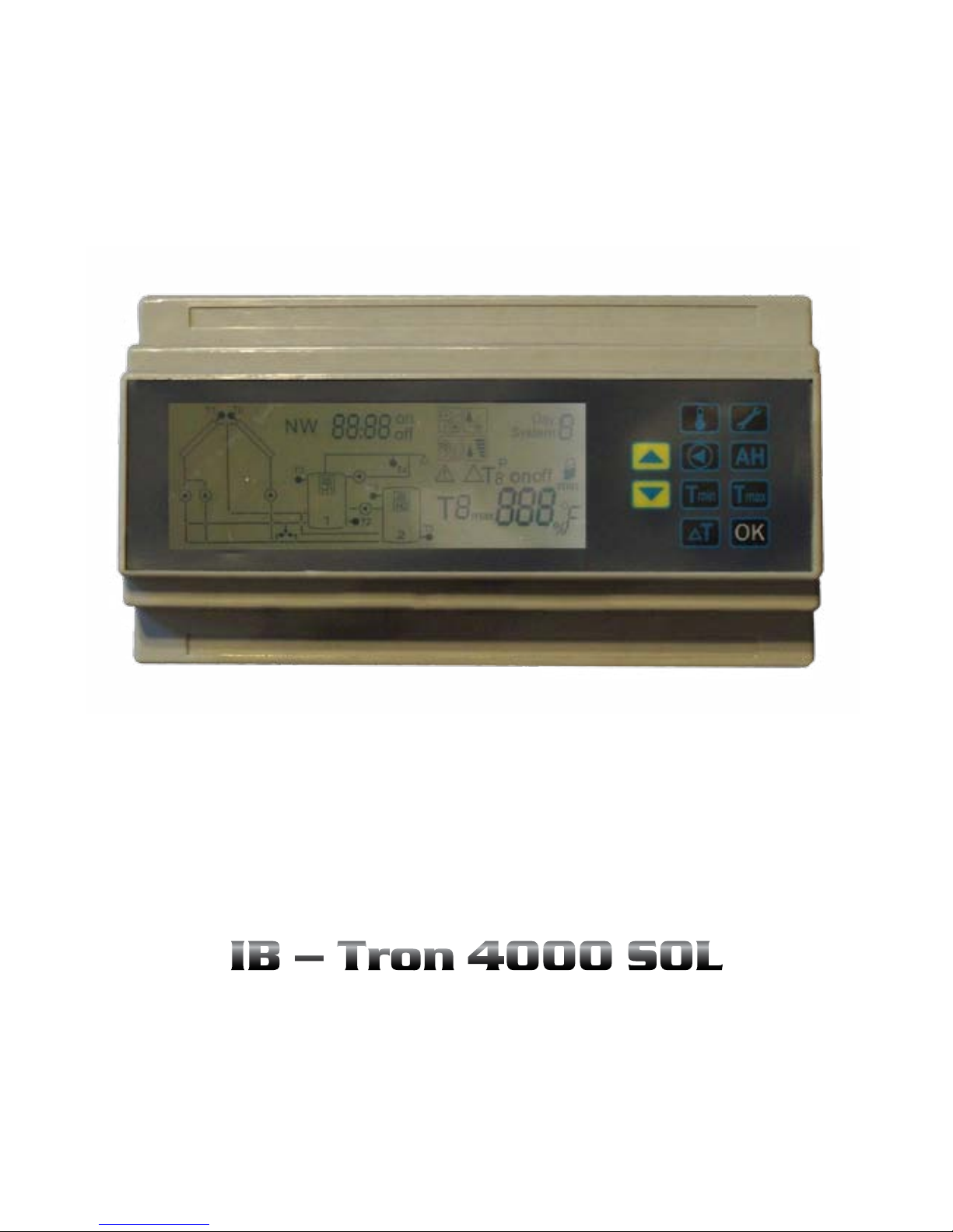
INSBUD IB-TRON 4000 SOL User manual
Multisystem solar controller
With support for additional devices, two collectors areas,
for central and water heating.
IB – Tron 4000 SOL

www.insbud.net 3
English
InsBud company supports policy of development. Rights to making changes and
improvements in products and manuals without prior notice reserved!
The contents of this manual - the text and graphics are owned by InsBud company
or its subcontractors, and is legally protected.
Products is marked
and has been produced in accordance with ISO 9001 standard
v1.22
Contents
iB-TROn 4000 sOl
Basic information __________________ 4
Features _________________________ 4
Available Models __________________ 5
Technical data_____________________ 5
Supply___________________________ 5
General Remarks __________________ 5
Construction______________________ 6
Wiring ___________________________ 6
Display __________________________ 7
Temperature sensors _______________ 7
Calibration _______________________ 8
Temperatures overview _____________ 9
Basic settings _____________________ 9
Fresh water circulation pump ________ 10
Bacteriological protection ___________ 11
Hysteresis ________________________ 11
Extra heating busters _______________ 11
Frost protection ___________________ 13
High temperature protection ________ 13
Choice of tank_____________________ 14
Loading pumps ___________________ 14
P0 and P1 pump speed _____________ 15
SMART START _____________________ 17
GUARD __________________________ 17
Holidays _________________________ 17
Additional functions setting _________ 18
Keyboard lock_____________________ 18
Factory settings ___________________ 18
Test functions _____________________ 18
Temperature units _________________ 19
Network _________________________ 19
Software version___________________ 19
Errors____________________________ 20
Short manual _____________________ 20
Warranty _________________________ 22
„INSBUD”
ul. Niepodległości 16a
32-300 Olkusz
Poland
sales department: +48 (32) 626 18 00
sales department: +48 (32) 626 18 18
technical department: +48 (32) 626 18 07
technical department: +48 (32) 626 18 08
fax: +48 (32) 626 18 19
e-mail: insbud@insbud.net

www.insbud.netwww.insbud.net 54
English
English
Basic infORmaTiOn
fEaTuREs
fEaTuREs fEaTuREs
TEchnical daTa
supply
gEnERal REmaRks
availaBlE mOdEls
IB-Tron 4000SOL controller are used for con-
trol solar systems or any other heating sys-
tem, which control is based on measuring
dierence of temperature in dierent places
of system. IB-Tron 4000SOL controller ena-
bles full automation of these systems in a
comfortable way and it ensures high ecien-
cy of whole system.
eControl of 4 dierent expanded heating
systems
eIndependent control of two areas of so-
lar collectors
eLoading of two tanks (eg fresh water
tank and storage tank, fresh water tank
and a swimming pool etc.)
eAbility to connect 7 temperature sen-
sors (all sensors included)
eAbility to control 7 various devices
(pumps, heaters, valves, boilers, etc.)
eLoading pumps of collectors with auto-
matic dull range speed control for incre-
asing eciency of whole system. Speed
of pumps is calculated in two ways (de-
pends of user setting):
» according to optimum temperature
dierence
» according to optimal operating tem-
perature of collector
eFull adjustable hysteresis for all
parameters
eAnti-frost protection function for
collectors
eProtection against high temperature of
tanks (against overheating)
eAbsolute protection against excessively
high temperatures in system
eLegibly, large (4 „), backlit blue LCD di-
splay that shows all the necessary in-
formation (temperature, pumps, valves,
heaters status etc.) and the current ide-
ological view of instalation
ePower supply from building network -
does not require batteries to operate
eBattery memory backup in the case of
break of power supply.
eExtra heating busters independently for
each tank
eControls fresh water circulation pump
by modes:
» by temperature of circulation
» by time program of work and break
time
eHoliday function in two modes (de-
pends of user setting):
» Winter (heating building only,Fresh
water tank is not heated at all by so-
lar and other heating busters)
» Summer (cooling tanks and extra
heating busters not working at all)
eBacteriological protection of fresh wa-
ter tank
eGUARD function - protection devices
from damage
eReloading heat between tanks
eSMART START function, controller in-
telligently consider delay between real
temperature and sensor measuring
eIndependent calibration of each sensor
eChoice of how to load tanks:
» Highest eciency (system tries to
collect as much energy as possible,
both tanks are equivalent)
» Fresh water tank prioryty (Fresh wa-
ter tank is rst loaded to the optimum
temperature as priority and after that
both tanks are loaded according to
highest eciency method)
eManual test of all relays
eThe ability to verify operation of the lo-
gic by temperature readings overwrite
eMounting on DIN rail (10 modules) or
on-wall mounting
eEasy and intuitive handling
eAesthetic and modern look
eNetwork RS485 or Ethernet communi-
cation (optional)
ePower consumption: <5W
ePower supply: 230V AC
eAccuracy: ±1 ºC
eStorage temperature: -10÷50 ºC
eMax load:
» P0, P1: 1,5A (~300W)
» P2, P3: 3A (~600W)
» R1: 10A (~2000W)
» H1, H2: 16A (~3500W)
ePlastic cover: ABS
eDisplay: LCD (4”)
eHumidity: 5±90%
eClock accuracy: ±100 s/month
e1x Controller
e2x Sensor PT1000
e5x Sensor NTC10kOhm
e1x This instruction
e1x Instructions for network (only with
NW model NW)
HDuring the installation of controller po-
wer supply should be cut o. This pro-
duct should be installed by a qualied
electrician.
HController should be placed away from
showers, bathtubs, washbasins, etc. to
prevent direct ooding of controller.
HController is designed for installation in
electric distribution box with standard
DIN rails. It can be also mounted on-
wall by special mounting holes.
eBL - blue backlight (backlight is activa-
ted when pressing any button and it is
turned o after some delay)
eNW - controller for network (communi-
cation by RS - 485 or Ethernet)
www.insbud.netwww.insbud.net 76
English
English
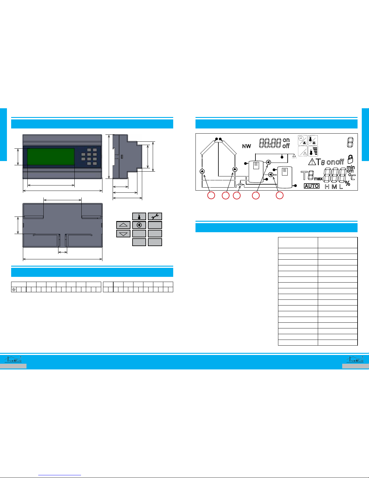
cOnsTRucTiOn
WiRing
display
TEmpERaTuRE sEnsORs
159
159
94
59
49
30
3335
88
47
61
77
18
POWER R1H1 H2 P0 P1 P2 P3
NONN N N N N NL OFFL L L L L L N
T0 T1 T2 T3 T4 T5 T6
eConnection terminals are located under
front panel. To connect wiring please re-
move front panel and disconnect wiring
cable from main board.
ePOWER - Power supply
eConnection various devices and sen-
sors depends of chosen system of
work. Some devices or sensors may be
not connected. All connected devices
must have the same power supply like
controller.
eR1 - Controlling terminal of 3-way valve.
Controller gives voltage at ON output
when it want to load tank 2 (buer), and
gives the voltage at OFF output when it
want to load tank 1 (fresh water tank)
Day
T1
T3
T6
T5
T2
H1
T4
T0
1
P
System
2
H2
P0 P2 P3
R1
P1
eThe appearance of display depending
of chosen system of work. Some items
may not be visible.
eFlashing pump symbol means that this
pump works at the moment. If the sym-
bol is not ashing means that pump
does not work now.
IWith controller are provided follow
sensors:
» 2x PT1000 Sensors (connected to T0
and T1)
» 5x NTC10kOhm Sensors (connected
to T2, T3, T4, T5 i T6)
IThe sensors can be extended to any
length, but it must be remembered that
the extension above 10m may cause de-
viation of temperature measurement,
so for a distance above 10m controller
should be calibrated. Sensor wires must
be extended by cables:
» to 50m 2x 0,75 mm2
» above 50m 2x 1,50 mm2
eController is compatible with NTC 10kΏ
sensors witch follow characteristic:
Temperature
[ºC]
Resistance
[Ώ]
-50 687 803
-40 346 405
-30 181 628
-20 99 084
-10 56 140
0 32 960
10 20 000
20 12 510
25 10 000
30 8 047
40 5 310
50 3 588
60 2 476
70 1 743
80 1 249
90 911
100 647
AH
Tmin Tmax
∆T OK

www.insbud.netwww.insbud.net 98
English
English
TEmpERaTuRE sEnsORs TEmpERaTuREs OvERviEW
Basic sETTings
Basic sETTingsTEmpERaTuRE sEnsORs
eSensors cables are low-voltage, so as
not to interfere with the measurements,
sensor wires should not be conducted
in the vicinity of high voltage cables (the
distance of at least 100mm).
eThe sensors can operate in all weather
conditions.
» Sensors cables are resistant to tem-
perature:
» PT1000: -50÷140 ºC, temporary to
200 ºC
» NTC 10kΏ: -50÷100 ºC, temporary to
120 ºC
eIf sensor is not connected or damaged
and it is not important for controller
operation on display you can see „- - -”
value
IIf sensor is not connected or damaged
and it is important for controller ope-
ration on display you can see warning
symbol
First of all you need to set an appropriate sys-
tem of work, which will correspond to actual
installation of hydraulic connecting.
Controller supports 4 heating systems:
1. One collector area and one tank
2. Two collector areas and one tank
3. One collector area and two tanks
4. Two collector areas and two tanks
IIn fact, areas of collectors may be any
other device that generates heat in a
similar way to a collector (eg, heating
replace). A similar situation is with the
tank, which in fact may be, for example
swimming pool.
To select an appropriate system please:
eController is compatible with PT1000
sensors witch follow characteristic:
Temperature
[ºC]
Resistance
[Ώ]
-30 862
-20 902
-10 944
0 1 000
10 1 057
20 1 097
30 1 136
40 1 175
50 1 215
60 1 254
70 1 292
80 1 331
90 1 370
100 1 408
110 1 447
120 1 485
130 1 523
140 1 561
150 1 599
160 1 597
170 1 645
180 1 712
190 1 750
200 1 787
210 1 774
220 1 810
230 1 847
240 1 875
250 1 912
260 2 008
270 2 045
280 2 081
caliBRaTiOn
After properly connecting controller is ready
to work. Controller is factory-calibrated to
work with standard sensors. However after
extension temperature displayed by control-
ler may be dierent from actual.
In that case, you can calibrate the device.
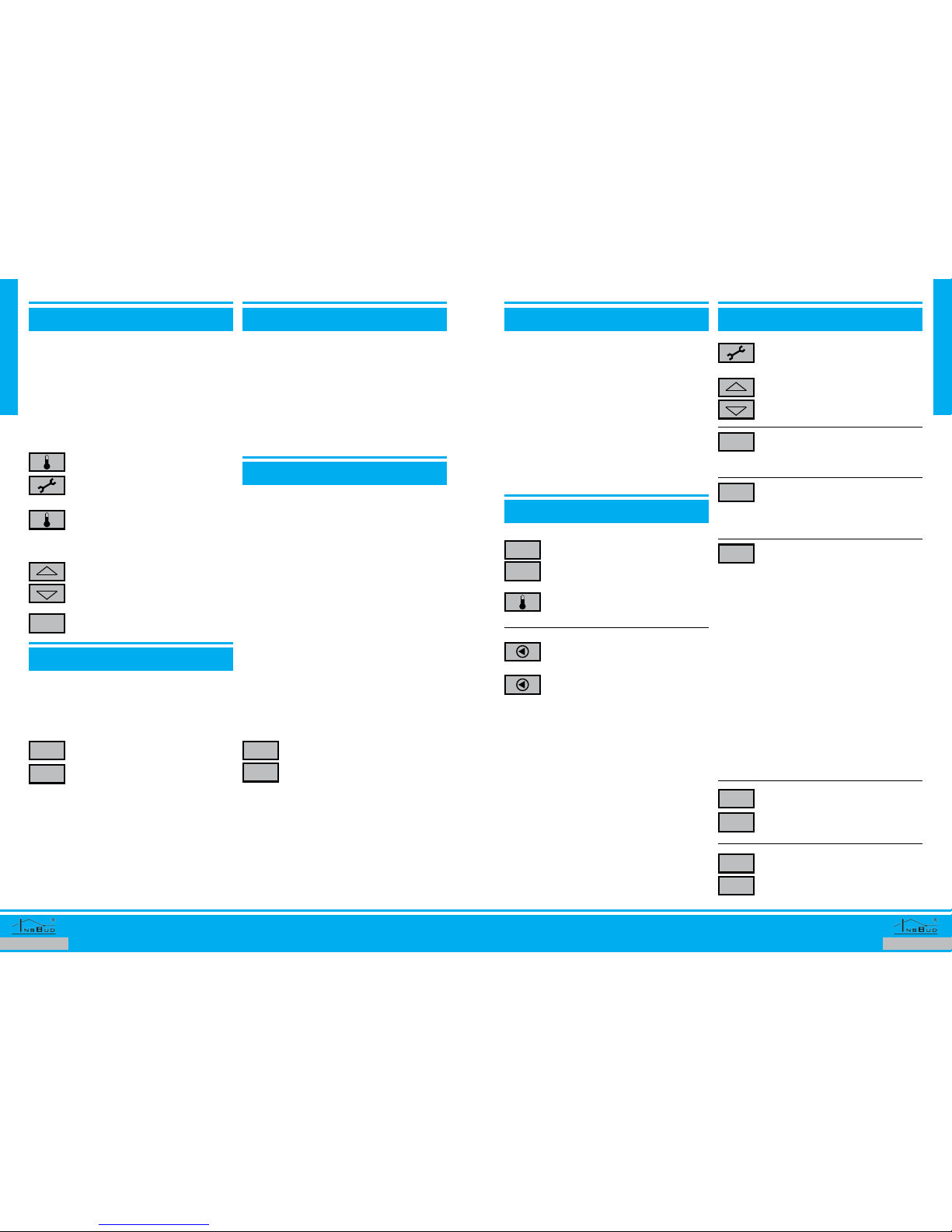
Each sensor is calibrated separately:
Press and hold two buttons simul-
taneously. On display start ashing
current calibration settings and
number of sensor.
Press the button. On display there
will be ashing system number in
the right upper corner.
Press the button. On display there
will be ashing hour.
Press the button. On display the-
re will be ashing day of the week
(number 1÷7).
To see a specic temperature sen-
sor, press button. Repeated pres-
sing of this button will switch to the
next sensor indications. If current
temperature sensor is last available
sensor, another button press will
switch to the rst available sensor.
To be able to easily nd out where
specic sensor is located, all sen-
sors have been symbolically mar-
ked on the display and next to it is
number of sensor.
Calibrate sensor by setting the ap-
propriate value settings.
Select desired system (during the
selection display will be updated
automatically).
Set current hour. Longer holding
the button will change settings
faster.
Set current day of the week.
By repeatedly pressing button you
can change calibrated sensor.
Conrm set data.
Tmin
OK
∆T

www.insbud.netwww.insbud.net 1110
English
English
fiRsT sysTEm - OnE cOllEcTORs aREa and OnE Tank
sEcOnd sysTEm - TWO cOllEcTORs aREa and OnE Tank
The circulation pump of collectors area (P1) is
started when temperature dierence of col-
lectors area (T1) and tank temperature (T2)
reaches the set value of switching on. The
pump is turned o when temperature die-
rence of T1 and T2 falls below the set value of
switching o or temperature in the tank (T2)
reaches the set maximum value. The pump
of the collectors is controlled with continu-
ously speed adjustment.
External power supply (H1), which may be a
electric heater, gas stove or components of
automation (pump, valve) is controlled on
the basis of respectively set parameters of
the controller, which are described later in
this manual and temperature reading of sen-
sor (T3) in the upper part of the tank. Circu-
lation pump of hot water (P2) is controlled
on the basis of respectively set parameters
of the controller, which are described later in
this manual and temperature reading of sen-
sor (T4) of hot water circulation.
Above remarks connected with external heat
source and hot water circulation pump con-
cern to all supported systems.
Circulation pump of the rst collectors area
(P1) is started when temperature dierence
of the rst collectors area (T1) and tempe-
rature in the tank (T2) reaches the set value
of switching on. Similarly, circulation pump
of the second collectors area (P0) is started
sEcOnd sysTEm - TWO cOllEcTORs aREa and OnE Tank
ThiRd sysTEm - OnE cOllEcTORs aREa and TWO Tanks
adjustment.
This system is recommended when areas of
the collectors are working independently for
each other (east-west layout with a low slope,
there may be a case when two collectors are-
as are working simultaneously).
In fact, the second collectors area may be re-
spectively hydraulically connected another
device which produces thermal energy for
example: heating replace.
when temperature dierence of the second
collectors area (T0) and temperature in the
tank (T2) reaches the set value of switching
on. Circulation pumps (P1 and P0) are wor-
king independently from each other - the
pumps may work simultaneously, don’t work
at all or one pump works. Suitable pump is
turned o when temperature dierence be-
tween the suitable collectors area and the
tank falls below the set value of switching
o or temperature in the tank (T2) reaches
the set maximum value. Pumps of collec-
tors are controlled with continuously speed
The circulation pump of collectors area (P1) is
started when temperature dierence of col-
lectors area (T1) and temperature in the tar-
get tank (T2 or T5) reaches the set value of
switching on and three-way valve is set in the
position to load appropriate tank. Tanks are
loaded according to the selected priority (de-
scription is later in this manual). The loading
pump (P1) is turned o when temperature dif-
ference between collectors area and loaded
tank falls below the set value of switching o
or temperature in the tank (T2 or T5) reaches
the set maximum value. The pump of the col-
lectors is controlled with continuously speed
adjustment.
There is a posibility to pump heat between
tanks (description is later in this manual).
External power supply (H2), which may be
electric heater, gas stove or components of
automation (pump, valve) is controlled on
the basis of respectively set parameters of
the controller, which are described later in
this manual and temperature reading of sen-
sor (T6) in the upper part of the buer tank.
In fact, the second tank may be respectively
hydraulically connected swimming pool.
Day
T1
T3
T2
H1
T4
1
P2 P
P1
System
Day
T1
T3
T2
H1
T4
T0
1
P2 P
P1 P0
System
Day
T1
T3
T6
T5
T2
H1
T4
1
P2 P
P1
System
2
H2
www.insbud.netwww.insbud.net 1312
English
English
fREsh WaTER ciRculaTiOn pump fREsh WaTER ciRculaTiOn pump
Controller is equipped with a fresh water cir-
culating pump control function (P2 pump).
Control of fresh water circulating pump can
be done in two ways:
1. Control based on return
temperature of fresh water
circulation. If fresh water
pump control is by this me-
thod, special symbol is visible on di-
splay. T4 sensor must be connected to
use this control method. Fresh water
circulation pump is turned on when
temperature on T4 sensor drops be-
low set value. It is recommended that
T4 sensor be placed on return pipe of
fresh water circulation or just before
last fresh water receiver. To this place,
fresh hot water will be pushed and
then fresh water pump will be turned
o. Just as water pipe in the circula-
ting pump will cool down, fresh water
circulation pump will be turned on.
Attention. If the temperature in the
upper part of tank No 1 (T3) is too
low to warm T4 sensor to desired
temperature, the circulation pump
will not be turned on.
2. Control based on time pe-
riods. f fresh water pump
control is by this method,
special symbol is visible on
display. Controller controls fresh water
pump according to periods of time:
work time and break time. E.g. Cir-
culation pump is turned on every 20
min for 3 min. Both periods are
adjustable.
eIf on display is not showed any of above
symbols, this means that fresh water cir-
culation pump is not controlled by con-
troller at all.
eIf fresh water circulation pump is wor-
king P2 symbol on display is ashing.
eFresh water circulation pump is control-
led only in set daily periods of time (only
between beginning and end of the pe-
riod). Often there is no need for circula-
tion pump control during the night or
when no one is in the building. Apart
from these periods circulation pump
never turns on.
To choose method of control of fresh water
circulation pump please:
Repeatedly press the button.
Press and hold button.
Repeatedly press the button to set
further parameters:
T4on - Value of temperature [ºC]
below which fresh water circula-
tion pump is turned on (parameter
adjustment available only for rst
method of control)
T4o - Hysteresis between turning
on and turning o fresh water cir-
culation pump (parameter adju-
stment only for rst method of
control)
on - Work time period [min] - how
long the pump has to work in one
cycle (parameter adjustment ava-
ilable only for second method of
control)
After selecting control method, you can set
the parameters of control function. Depen-
ding on selected control method there are
dierent parameters settings. To adjust para-
meters of function please:
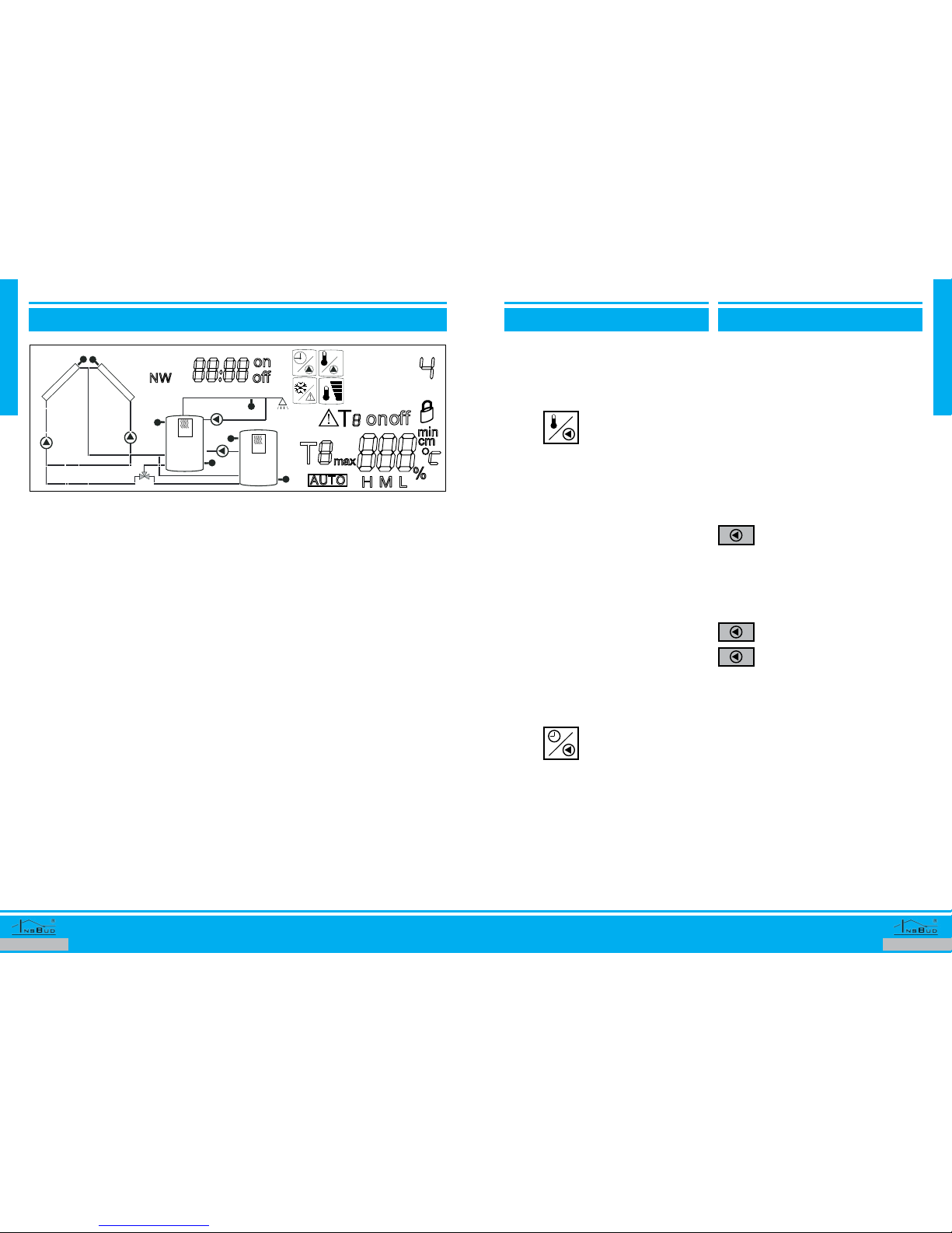
fOuRTh sysTEm - TWO cOllEcTORs aREas and TWO Tanks
Circulation pump of the rst collectors area
(P1) is started when temperature dierence
of the rst collectors area (T1) and tempera-
ture in the target tank (T2 or T5) reaches the
set value of switching on. Similarly, circula-
tion pump of the second collectors area (P0)
is started when temperature dierence of
the second collectors area (T0) and tempera-
ture in the target tank (T2 or T5) reaches the
set value of switching on. Circulation pumps
(P1 and P0) are working independently from
each other - the pumps may work simultane-
ously, don’t work at all or one pump works.
Three-way valve (R2) is set in the position to
load appropriate tank. Tanks are loaded ac-
cording to the selected priority (description
is later in this manual). Suitable loading pump
is turned o when temperature dierence
between the suitable collectors area and
the loaded tank falls below the set value of
switching o or temperature in the tank (T2
or T5) reaches the set maximum value. The
Pump of collectors is controlled with conti-
nuously speed adjustment.
There is a posibility to pump heat between
tanks (description is later in this manual).
This system is recommended when areas of
the collectors are working independently for
each other (east-west layout with a low slope,
there may be a case when two collectors are-
as are working simultaneously).
External power supply (H2) works as in the
third system.
In fact, the second collectors area may be re-
spectively hydraulically connected another
device which produces thermal energy for
example: heating replace.
In fact, the second tank may be respectively
hydraulically connected swimming pool.
Day
T1
T3
T6
T5
T2
H1
T4
T0
1
P2 P
P1 P0
System
2
H2

www.insbud.netwww.insbud.net 1514
English
English
Repeatedly press the button to set
further parameters:
T3 on - T3 comfortable tempera-
ture - up to this temperature rst
tank is heated by H1
T3o - Hysteresis for H1 - applica-
ble for T3
T3 P1 on - First period of H1: be-
ginning of period
T3 P1 o - First period of H1: end
of period
T3 P2 on - Second period of H1:
beginning of period
T3 P2 o - Second period of H1:
end of period
T6 on - T6 comfortable temperatu-
re - up to this temperature second
tank is heated by H2 (only for sys-
tems with two tanks)
T6 o - Hysteresis for H2 - appli-
cable for T6 (only for systems with
two tanks)
T6 P1 on - First period of H2: be-
ginning of period (only for systems
with two tanks)
T6 P1 o - First period of H2: end
of period (only for systems with
two tanks)
T6 P2 on - Second period of H2:
beginning of period (only for sys-
tems with two tanks)
T6 P2 o - Second period of H2:
end of period (only for systems
with two tanks)
ExTRa hEaTing BusTERs ExTRa hEaTing BusTERs
water in tanks (directly or by exchange coil),
etc.
Please note that the maximum load of H1
and H2 can not exceed values given in tech-
nical data of this manual. For bigger loads of
extra heating busters please use additional
external relays of adequate power.
Controller is designed for extra heating bu-
sters located in upper parts of tanks so that it
does not heat whole tank just top part of it.
If temperature in upper part of rst tank (T3)
drops below comfortable set value (for spe-
cic period of time) H1 device will be turned
on until it reach desired comfortable tempe-
rature (including hysteresis value).
Similarly H2 deviece is turned on when tem-
perature in upper part of second tank (T6)
drops below comfortable set value.
For each tank can be set two independent
periods of time (for a day) in which extra he-
ating busters are controlled (outside this pe-
riods extra heating busters are never turned
on).
To adjust parameters of the function please:
AH
Set desired value of the parameter.
Conrm set data.
OK
IIn some heating systems, it is desirable
that temperature at top of buer tank
(tank 2) was variable and dependent
on outside temperature (colder outside
- higher required temperature T6, war-
mer outside - lower required tempera-
ture T6). This eect can be achieved by
additional linear weather compensator.
Such controllers are available in our
oer.
fREsh WaTER ciRculaTiOn pump
BacTERiOlOgical pROTEcTiOn
BacTERiOlOgical pROTEcTiOn
ExTRa hEaTing BusTERs
o - Break time period [min] - ever
this time period circulation pump
will be turned on (parameter ad-
justment available only for second
method of control)
P1 on - Beginning of rst period of
work
P1 o - End of rst period of work
P2 on - Beginning of second pe-
riod of work
P2 o - End of second period of
work
Set desired value of the parameter. select temperature protection va-
lue (recommended value is 70 ºC)
or turn OFF protection function.
Conrm set data.
OK
Caring for health of user, the controller is
equipped with bacteriological protection of
fresh water tank, this feature prevents the
tank before legionell bacteria (legionnaires).
Optimal temperature for growth of the Le-
gionella pneumophila bacteria in the labo-
ratory is 37ºC. At higher temperatures these
micro-organisms proliferation decreases, at
46ºC it stops. Bacteria can survive at higher
temperatures, but decreases survival time of
several hours at 50ºC and of few minutes at
60ºC. At 70ºC bacteria is killed instantly.
Controller controls maximum temperature
which was in fresh water tank within 7 days. If
at that time temperature in fresh water tank
remained at low level there is a risk of bacte-
ria appearance. Therefore, if such a situation
occurs (temperature in fresh water tank for 7
days, will not increase above the set protect
value), controller is turning on an additional
source of heat (extra heating buster) H1 and
remains turned on until protection tempera-
ture will be achieved.
Bacteriological protection function is recom-
mended in all cases, but you can disable it if
necessary.
To enable / disable bacteriological protection
function please:
Controller is equipped with additional, inde-
pendent, strong relays H1 and H2, into which
you can connect an additional source of heat
(extra heating busters). This source of heat
may be e.g. electric heater, gas boiler heating
Press and hold button.
Conrm set data.
OK
hysTEREsis
Controller allows full adjustment of hystere-
sis for multiple functions.
Hysteresis is delay between turning on/o of
device Higher value of hysteresis means less
cycles of controlled device (e.g. pumps) and
thus increases the vitality of the device.
In normal conditions it is recommended to
set hysteresis value to 2 ºC (for liquid). Value
setting of hysteresis depends on where the
measurement is.
www.insbud.netwww.insbud.net 1716
English
English
IDisplay symbolically show valve posi-
tion and in addition some parts of in-
stallation are ashing. In this way, in
clear and unambiguous way user gets
information that what tank is being lo-
aded now.
lOading pumps
Generally speaking, controller loads tanks
where temperature is higher than in destina-
tion tank (with appropriate modications to
respective systems).
For all collectors areas (T0 or T1) you can set
turn on/o temperature dierence of pump
P0 or P1. Analyzed dierence refers to ap-
propriate collector area and destination tank
(This may be T2 or T5 depending on which
tank controller decides to load). Values of
these parameters should be set individually
to each installation.
According to a simplied method turn on
temperature dierence should be:
Temperature losses arising on installation (in
standard conditions of heating) on distance
between the analyzed collector area and far-
thest tank and this value increased by 4 ºC.
Conversely, turn o temperature dierence
of the same collector area should not be less
than above temperature losses.
For example, losses between collector and
tank are 4 ºC. Turn on temperature dierence
should be 8ºC and turn o temperature die-
rence should be 4ºC.
Controller has been additionally equipped
with control of re-loating pump P3. This fe-
ature is very necessary in many cases, an
example of this may be the typical situation:
chOicE Of Tank chOicE Of Tank
The issue concerned for two tank systems (3
and 4).
Controller selects which tank is loaded in two
ways (method of selection is determined by
user choice):
1. First tank priority method. As long
as rst tank (sensor T2) did not reach
desired optimal temperature, second
tank is not loaded (exception is case
when controller determines that the-
re is no chance to load rst tank to
desired optimal temperature). When
rst tank is loaded to optimal tempe-
rature, both tanks are loaded by most
eciency method.
2. Most eciency method. First and
second tank have equal rights. Con-
troller loading tank which will provi-
de greatest yield of energy in whole
system (NOTE! Please do not confuse
energy with temperature!)
To adjust parameters of this function please:
Press and hold button.
Repeatedly press the button to set
further parameters:
1. Optimal T2 temperature (for
rst method of choice)
2. Method of tank choice (by
former description)
Set desired value of the parameter.
Conrm set data.
OK
AH
AH
high TEmpERaTuRE pROTEcTiOn
high TEmpERaTuRE pROTEcTiOnfROsT pROTEcTiOn
Controller is equipped with tanks and
entire system protection against high
temperatures.
If T0 or T1 temperature exceeds set safety
temperature, respectively, P0 or P1 pump is
turned o as priority, so high temperature,
which may appear don’t damaged compo-
nents mounted on installation. These values
should be set at level which instantaneous
resistance to high temperature has on the
weakest part of solar installation.
If T2 or T5 temperature exceeds set safety
temperature, the corresponding tank is not
loading anymore (until temperature drops)
because of safety. These values should be
lower than maximum allowable temperature
for tank (this information should be given by
manufacturer of tank).
All of these security features may be disabled.
However for safety reasons, it is strongly not
recommended.
To adjust this functions please:
If controller nds that temperature in the col-
lectors (T0 or T1) drops below safe frost limit,
it will turn on loading pump (P0 or P1) with
maximum speed, to protect collector from
damage.
To adjust this function please:
eSetting range of safe frost limit is 5 ÷
-30ºC
eSafe frost limit value should be respon-
sible for freezing level of used liquid
(e.g. if it is glycol of freeze level -15ºC,
safe frost limit value should be at this or
higher value).
eIf solar system uses completely non-fre-
eze liquid, you can disable this function
(for only one or two areas).
IIf frost protection function is current
activated on display warning symbol
appears.
Set desired protection value (safe
frost limit) or turn OFF protection
function.
Conrm set data.
OK
Tmin Repeatedly press the button to set
appropriate collectors area.
select temperature protection va-
lue or turn OFF protection function
for choosen senso.
Conrm set data.
OK
Repeatedly press the button to
choose temperature sensor for
protection function setting.
Tmax
IIf frost protection function is current
activated on display warning symbol
appears.
www.insbud.netwww.insbud.net 1918
English
English
p0 and p1 pump spEEd p0 and p1 pump spEEd
re (T0 or T1) was always at constant
optimal level (eg 80ºC)
2. Based on optimal temperature dif-
ference between supply and return.
Speed of the pump is calculated that
dierence of temperature at collector
(T0 or T1) and destination tank (T2
or T5) Was always at constant optimal
level (optimal growth of temperature
for example 20ºC)
To properly determine how speed should
be calculated please ask manufacturer of
collectors. At time of writing this manual,
InsBud vacuum tube collector (classic and
SHCMV) have optimal performance with
method 2 and value of dierence with
20ºC. These values are default settings of
controller.
IController controls of pump speed,
which only has an impact on ow spe-
ed. Therefore rst of all please set opti-
mal ow speed for 80% speed of pump
by suitable balance valve placed just
before pump.
IController has been designed to con-
trol classic pumps currently available
on market. Due to variety of available
pumps we recommend using original
IB-Pump xx-60. By using this pump we
guarantee valid proportional control
of speed. Using other pumps (eg with
dierent strength, dierent type of en-
gine), you must reckon with possibility
that pump will be regulated in steps (not
proportional) or not extent as provided
for in controller algorithm.
Controller allows to adjust minimal speed
of P0 i P1 pump. This means that a suitable
pump will never work with lower speed than
set value. Setting minimal value for 100%
means that pump is only turned on and o
(no speed control).
Minimal speed value of pump is default set
to 10%. This value should be changed only in
two cases:
ePump with minimal speed makes vi-
bration and loud voice in system (very
specic situation for hydraulic installa-
tion). Then gradually increase the mini-
mum speed of the pump until vibration
stops.
eControlled pump is an advanced elec-
tronic pump, dynamically changing its
own speed by its own built-in controller.
In this case, set minimum speed value
to 100% and for safety of pump and its
controller we recommend to connect to
it by separated external relay.
To adjust parameters of this function please:
Tmax
Tmax
Press and hold button.
Repeatedly press the button to set
further parameters:
1. Speed control method (me-
thod common to both lo-
ading pumps according to
above description)
2. Optimal operating tempe-
rature (for rst method)
3. Optimal temperature die-
rence (for second method)
4. Minimal speed for P0
5. Minimal speed for P1
Set desired value of the parameter.
Conrm set data.
OK
lOading pumps lOading pumps
Solar system for whole day heat both tanks
completely (1 and 2). First tank is fresh water
tank. At evening residents of building cool
rst tank (hey used hot water). Normally, at
this point extra heating buster should be
turned on to heat fresh water tank (such as
electric heater – extra heating buster feature
has been previously described in this manu-
al). However, when second tank is still collec-
ted by solar energy, this energy is re-loaded
from second tank to rst fresh water tank (for
example by upper coil exchanger in fresh wa-
ter tank or by external exchanger). This featu-
re allows maximum solar energy use in who-
le system. When re-loading process is active
H1 extra heating buster is turned o.
Control of P3 re-loading pump is in same
way like P0 and P1 pumps, but for calcula-
tion controller using temperatures in the up-
per parts of both tanks (dierence between
T6 and T3).
IP0 and P1 pump working with variable
speed. This speed is calculated by con-
troller (more details later in this manu-
al). P3 pump works as turn on/o with
constant speed.
IIf any pump is working its symbol on di-
splay is ashing.
To adjust parameters of this function please:
Repeatedly press the button to set
further parameters:
1. Turn on dierence for P0
2. Turn o dierence for P0
3. Turn on dierence for P1
4. Turn o dierence for P1
5. Turn on dierence for P3
6. Turn o dierence for P3
Set desired value of the parameter.
Conrm set data.
OK
∆T
p0 and p1 pump spEEd
As you know the speed of uid ow through
the collector is not neutral. If ow speed is too
high, the collector will not be operated with
maximum eciency. If too low, the collector
may fall within the zone of steam.Set of ow
speed at a constant level is only simple so-
lution because this ow speed is optimal for
conditions that were at the time of ow spe-
ed adjustment. If intensity of solar radiation
will change, collector return temperature will
changes automatically also other parameter
will change, after that optimal ow speed (at
which collector has highest eciency and
produces the most energy for current situ-
ation) is very dierent than one previously
set.
Only solution to this problem is automatic
control and ability to change ow speed of
liquid through collector. IB-Tron 4000SOL
controller it is equipped with such a possibi-
lity. Controller controls loading pumps speed
in proportional way so solar collectors are al-
ways working with its highest eciency.
In addition, due to fact that on market there
are many types of solar controllers (and other
equipment working on a similar principle)
calculation of optimal speed can be in two
methods:
1. Based on optimal operating tempe-
rature of collector. Speed of pump
is calculatet that supply temperatu-

www.insbud.netwww.insbud.net 2120
English
English
addiTiOnal funcTiOns sETTing
kEyBOaRd lOck
facTORy sETTings
TEsT funcTiOns
To adjust parameters of additional functions
(SMART START, GUARD, HOLIDAYS) please:
After properly setting of controller it is possi-
ble to lock keyboard to prevent setting mo-
dication. When controller is locked it does
not respond to keyboard pressing and on di-
splay is visible symbol of lock. To lock/unlock
keyboard please:
To reset controller and go back to factory set-
tings please:
Controller has a relays test function. Each re-
lay can be manually turned on/o and for P0
and P1 pump it is possible to set test speed.
To activate relay test function please:
∆T
∆T
Press and hold button.
Repeatedly press the button to set
further parameters:
1. SMART START for P0
2. SMART START for P1
3. GUARD function
4. HOLIDAY function (method
of work according to above
description).
By repeatedly pressing button you
can change testing relay.
Set desired value of the parameter.
Set relay status.
Conrm set data.
Conrm set data.
OK
OK
∆T
OK
Press and hold two buttons
simultaneously.
Press and hold two buttons
simultaneously.
Press and hold two buttons
simultaneously.
AH
hOlidays
P3 pump is turned on (to cool tanks)
2. Winter holidays. Excluded from ope-
ration is only the rst tank (fresh wa-
ter tank). It will be not heated by so-
lar system. Re-loading P3 pump and
fresh water circulation P2 pump ne-
ver turn on. The same with H1 extra
heating buster. Second tank (buer
tank) Works normally so solar energy
is available for use in central heating
process. H2 extra heating buster rów-
nież działa wg podstawowych kryte-
riów, Also works normally to not di-
srupt process of building heating .
p0 and p1 pump spEEd
ITo see current speed of the pump
please:
AH
Press and hold two buttons simul-
taneously. On display you will see
current speed of P0 pump.
Press and hold two buttons simul-
taneously. On display you will see
current speed of P1 pump.
smaRT sTaRT
Distribution of temperature in collector is
not linear and also sensor in collector is not
physically placed in theoretical ideal place.
Therefore in fact often happens that collec-
tor, could start work earlier few minutes than
this happened in practice. While in days with
high solar radiation this energy losses arising
from this delay is negligible, but in winter
days with lower solar radiation there is quite
a lot of this energy losses.
To solve this problem and increase energy
output IB-Tron 4000SOL controller is equip-
ped with a special algorithm which analyze
in dynamic, long term way behavior of indi-
vidual collectors areas. If controller comes to
conclusion that above situation may occurred
following several attempts to „push” heat to
sensor (with minimum speed loading pump
is turned on for short period of time), each
reaction is further studied by controller. If ac-
tion do not occur valid result (which means
that there is no conditions for load heat) con-
troller cease testing for other period of time
(this period is dynamic changeable).
Thanks to SMART START function signi-
cantly increases system eciency. For each
collector area this function is implemented
smaRT sTaRT
separately.
SMART START function May be disabled if
needed.
guaRd
Some of devices in whole system does not
work all year round. If the valve or pump is
not working for a long period of time it may
be damaged. Therefore it is important that
each device was periodically turned on even
when there is no need of it by logic of whole
system point of view.
This protective function of the fully is GUARD
function. It monitors work of all devices
connected to the controller.If any device was
not turned on for two weeks GUARD function
turn it on for one minute (in case of valve is a
full cycle of closing and opening).
GUARD function May be disabled if needed.
hOlidays
In case of leaving building for a longer period
oftime,itisdesirabletosetcontrollerinspecial
holiday mode, which modies principle of
system operation. Holiday function starts
and stops in manual way (after arrival from
holidays this function must be manually
disable). If you enable holiday function you
can see information about this on display.
Controller is equipped with two holiday
function methods, which can be selected
depending on situation:
1. Summer holidays. Extra heating bu-
sters H1 and H2 are strictly turned o
(never will be turned on). If tempera-
ture in any tank exceeds 40ºC P2 and
www.insbud.netwww.insbud.net 2322
English
English
ERRORs
On display may appear such symbols that’s
means:
eLO -temperature at current sensor is be-
low lowest measuring range.
eHI - temperature at current sensor is
above highest measuring range.
e--- - current sensor is not connected or
is damaged.
IIn an error occurs on display you will
warning sign.
shORT manual
shORT manual
Calibration. Press and hold two
buttons simultaneously.
By repeatedly pressing button you
can change calibrated sensor.
Tmin
Fresh water circulation pump pa-
rameters. Press and hold button.
Repeatedly press the button to set
further parameters:
1. Circulation pump turn on
temperature (method 1)
2. Work time for P2 [min] (me-
thod 2)
3. Break time for P2 [min] (me-
thod 2)
4. Beginning of rst period of
work
5. End of rst period of work
6. Beginning of second period
of work
7. End of second period of
work
Extra heating busters. Repeate-
dly press the button to set further
parameters:
1. Comfortable temp. T3
2. Hysteresis for H1
3. 1-st period H1: beginning
4. 1-st period H1: end
5. 2-nd period H1: beginning
6. 2-nd period H1: end
7. Comfortable temp. T6
8. Hysteresis for H2
9. 1-st period H2: beginning
10. 1-st period H2: end
11. 2-nd period H2: beginning
12. 2-nd period H2: end
AH
Select temperature protection
value.
Bacteriological protection. Press
and hold button.
Tmin Frost protection. Repeatedly
press the button to set appropriate
collectors area.
High temperature protection.
Repeatedly press the button to
choose temperature sensor for
protection function setting.
Tmax
Temperature units. Press and
hold two buttons simultaneously.
Tmin
Tmax
Software version. Press and hold
two buttons simultaneously.
Tmax
OK
∆T
TEsT funcTiOns
In addition, there is possible to test logic of
system work by sensor test function. When
this function is on, sensors no longer making
real measurement user are able to simulate
absolute values from controller keyboard
controller (simulate value of sensor).
To activate sensor test function please:
Press and hold two buttons
simultaneously.
By repeatedly pressing button you
can change testing sensor.
Set sensor status.
Conrm set data.
OK
nETWORk
TEmpERaTuRE uniTs
Controller is also available in versions desi-
gned to work in network.
There are versions based on RS-485 or Ether-
net communication.
Issues relating to network communication
are contained in separate manual for IBS
system.
Controller supports two temperature units:
ºC and ºF.
To change temperature units please:
Press and hold two buttons
simultaneously.
Tmin
Tmax
If you want update your controller to ne-
wer version please contact us or one of our
partners.
sOfTWaRE vERsiOn
InsBud company supports policy of develop-
ment. Thats why rights to making changes
and improvements in products and manuals
without prior notice reserved!
Our company is open to all suggestions to
improve our controllers. If you have any idea
to add new features or require unusual solu-
tions, please contact us.
This manual applies to controller with so-
ftware version number
011
If your controller has other software version in
operation and functionality may be dierent
from information contained in this manual.
To check software version please:
Press and hold two buttons
simultaneously.
Tmax
OK

www.insbud.netwww.insbud.net 2524
English
English
WaRRanTy
eWarranty is given for 24 months from
date of purchase of goods.
eAny defect disclosed in warranty period
will be removed within 21 working days,
counting from date of adoption of go-
ods for service.
eIn need of import goods or parts from
abroad, repair time is extended by time
required for their transportation.
eCustomer provides product to service at
their own cost.
eAt time of repair service will not provide
buyer replacement product
eWarranty repairs will be made upon pre-
sentation of properly and legibly lled
your hardware warranty card, signed by
guarantor and with sale document
eWarranty covers only defects arising
from causes inherent in goods. They
are not covered damage resulting from
external causes such as: mechanical in-
jury, pollution, ooding, weather, impro-
per installation or improper wiring and
operations. Warranty does not apply in
case customer’s unauthorized repairs,
changes in software (rmware) and de-
vice formatting.
eDue to natural material use, some of
them are not covered by warranty (for
example: cables, battery, charger, micro
switches, buttons).
eIn event of unjustied claims for warran-
ty repair, all additional cost are on custo-
mer’s side.
eService has right to refuse to perform
warranty repairs for following: dieren-
ces between documents and goods
marks, make repairs on their own by
customer, changes in product construc-
tion without authorization. This case
warranty is not valid anymore.
eIf it is not possible to test product be-
WaRRanTy
fore its purchase (sale at distance), it is
possible to return goods within 10 days.
Returned goods cannot bear signs of
exploitation, it must contain all elements
with which it was delivered.
eIn the case of return of purchased go-
ods all shipping costs are on buyer side.
Before return of goods please contact
with seller.
eTerms of warranty may be changed by
local InsBud company partner.
shORT manual
Choice of tank. Press and hold
button.
Repeatedly press the button to set
further parameters:
eoptimal T2 temperature (for 1
method)
eMethod of choice:
1. 1-st tank priority
2. Most eciency
shORT manual
Loading pumps. Repeatedly
press the button to set further
parameters:
1. Turn on dierence for P0
2. Turn o dierence for P0
3. Turn on dierence for P1
4. Turn o dierence for P1
5. Turn on dierence for P3
6. Turn o dierence for P3
∆T
Tmax
Tmax
Pump speed. Press and hold
button.
Repeatedly press the button to set
further parameters:
1. Method of speed control
(1 - based on optimal work
temperature; 2 – based
on optimal temperature
dierence)
2. Optimal work temperature
(1-th method)
3. Optimal temperature die-
rence (2-nd method)
4. Minimal P0 speed
5. Minimal P1 speed
AH
P0 P1
Pump speed view:
∆T
∆T
Additional functions. Press and
hold button.
Repeatedly press the button to set
further parameters
1. SMART START for P0
2. SMART START for P1
3. GUARD
4. HOLIDAY (1 – summer holi-
days; 2 – winter holidays)
∆T
OK
Keyboard lock. Press and hold
two buttons simultaneously.
Factory settings. Press and hold
two buttons simultaneously.
By repeatedly pressing button you
can change testing relay.
Relay test. Press and hold two
buttons simultaneously.
AH
Logic test. Press and hold two but-
tons simultaneously.
By repeatedly pressing button you
can change testing sensor.
AH
AH

ul. Niepodlegości 16a
32-300 Olkusz, POLAND
tel/fax +48 (32) 643-26-87
e-mail: insbud@insbud.net
Table of contents
Popular Control Panel manuals by other brands


Magellan
Magellan MG10LEDV User quick reference guide

AEG
AEG S 64.9 L Instructions for use

Steamist
Steamist TC-135 Installation and operating instructions

Menvier Security
Menvier Security TS2500 Operator's manual

EasiWise
EasiWise Standard Quick start user guide

Rosslare
Rosslare HLX-40 Installation and programming manual


