Marley Fluid Cooler Pump User manual

ISSUED 07/2014 READ AND UNDERSTAND THIS MANUAL PRIOR TO OPERATING OR SERVICING THIS PRODUCT.
Fluid Cooler Pump control panel
INSTALLATION - OPERATION - MAINTENANCE
Z0628618_C ISSUED 7/2020 READ AND UNDERSTAND THIS MANUAL PRIOR TO OPERATING OR SERVICING THIS PRODUCT.
user manual

2
introduction
NEMA 4X fiberglass outdoor enclosure with the following features:
• Hinged and lockable outer door
• Swing-out dead front inner door
• Corrosion resistant enclosure
Electrical Components
• External disconnect handle with padlocking provisions to meet lockout,
tag-out safety requirements
• Main circuit breaker with thermal and magnetic overload protection
• Door mounted operators • Pump starter
• Pilot lights • Status contacts
• Wiring diagram laminated and mounted on inside door
• Built to UL508 and CUL508 safety requirements
Options:
• Single Point Power Connection
• Integrated basin heater controls
• Integrated water level controls
• VFD feeder breaker if fan is controlled with remote VFD
• Factory installed and wired on selected products

3
These instructions are intended to assure that field connections are completed
properly and the control system operates for the maximum time possible. Since
product warranty may depend on your actions, please read these instructions
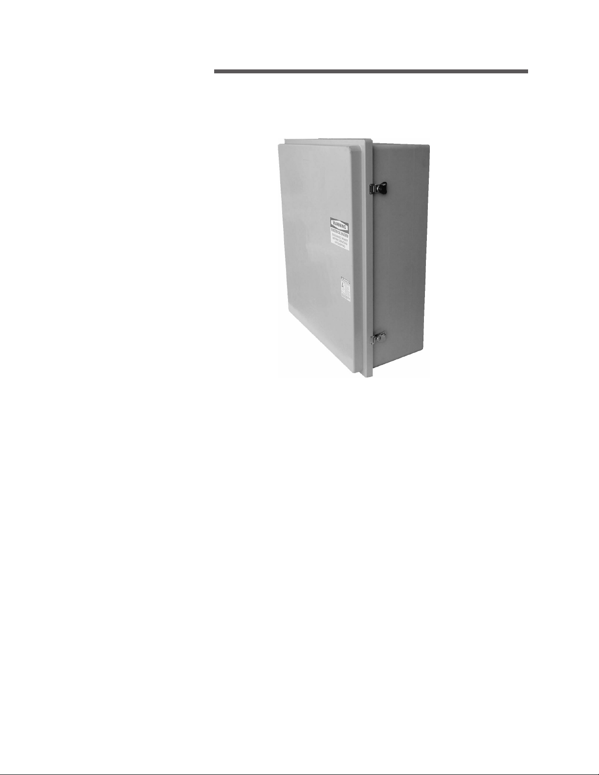
thoroughly prior to operation. Reference job specific wiring diagrams on the
inside of the CoolBoost pump control panel.
If you have questions about the operation and/or maintenance of this control
system and you do not find the answers in this manual, please contact your
Marley sales representative.
Hazard of electrical shock or burn. Be sure to turn off power to the
panel before servicing. If working on equipment out of site of panel
disconnect, lockout using standard lockout procedure.
Safety First
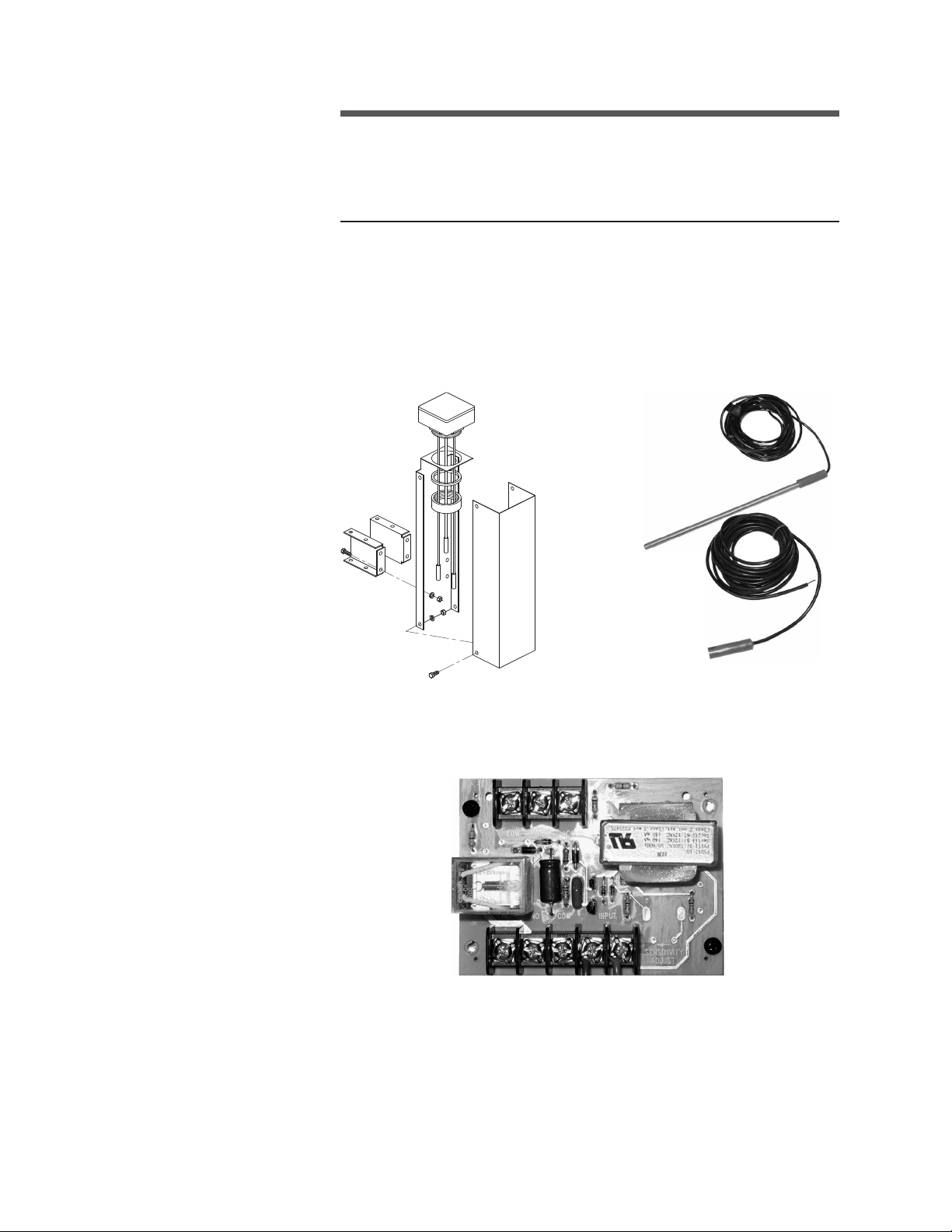
The Marley control system uses UL listed components installed in accordance
with the National Electric Code. The location of the cooling product and field
installation of the control system can affect the safety of those responsible
for installing, operating or maintaining the tower and controls. However,
since SPX Cooling Technologies does not control the tower location, or field
installation, we cannot be responsible for addressing safety issues that are
affected by these items.
The following safety issues should be addressed by those responsible
for installation, maintenance or repair of the tower and controls:
• Access to and from the control panel (including the customer
supplied main disconnect/branch circuit protection.)
• Proper grounding of electrical control circuits.
• Sizing and protection of branch circuits feeding the control
panel.
• Qualification of persons who will install, maintain and service
the electrical equipment.
These are only some of the safety issues that may arise in the design and
installation process. SPX Cooling Technologies strongly recommends that
you consult a safety engineer to be sure that all safety considerations have
been addressed.
Other safety issues are addressed in literature supplied with your
cooling product. You should closely review the literature prior to
installing, maintaining or repairing your cooling product.
Warning
Warning
Warning
introduction

4
installation
Circulating Pump Circuits
For the low-water safety circuit connect the two “low water probes”, located in
the basin stilling chamber to user terminal points in the control panel. Marley
probes are furnished with 20'-0" leads. Refer to the wiring diagram in the
control panel for connection points.
Stilling Chamber
Water Level Card
Water Level Probes

5
installation
Thermostat Installed on Casing Thermostat and Probe
Thermostat Probe Installation Thermostat
N.O. Contact
Adjustment Screw
Set at 35°F
For the freeze safety circuit run two 18 gauge control wires from the thermostat
located on the fluid cooler side casing to user terminal points in the control
panel. The thermostat has two sets of terminal points. Use either the left or
right two points oriented in a vertical column. Adjust the temperature range
so the red arrow on the left points to 35˚F as shown below.
The thermostat, provided with this system, requires adjustment.
Remove the inner most brass fitting located on the thermostat enclo-
sure to gain access to the adjusting screw. Adjust cut-out set point
temperature to 45˚F. This automatically sets the cut-in point at 35˚F.
Operation
Note
THERMOSTAT
PROBE
THERMOSTAT
PROBE

6
operation
Main Circuit Breaker: Operating handle for the main breaker is located behind
the outer door which is pad-lockable for lock out/tag out.
Rotating the handle to the OFF position turns power off to the panel.
Rotating the handle to the ON position provides power to the control panel.
If servicing the panel hot (door open and main breaker in energized position)
be sure to align the keyed slot on back of the operating handle with the key
on the main breaker shaft before closing the door.
Power ON Light: A pilot light indicates the main disconnect is on and the
control panel is powered.
Pump Operation
Standard operation of the pump is by manual control only, using a two-position
selector switch located on the door. A removable “run enable” jumper is
provided so customer may take control of cycling the pump. See the control
panel wiring diagram.
Cycling the pump on and off for temperature control could cause
scaling on the coils and is not recommended.
OFF-ON Selector Switch
• OFF position – pump motor is off.
• ON position – pump motor will run constantly unless a safety circuit
is activated.
If the water temperature in the cold-water basin drops to 35°F a N.O. contact
from the remote thermostat will close and latch-in a relay, which in turn shuts
off the circulating pump. This is a safety circuit to prevent pumping freezing
water. To reset this circuit, press the reset button on the door. The circuit can
be only reset once the cold-water basin temperature rises above 45°F.
If the basin water drops to a dangerously low level, the water level card contact
will close and also energize the latch-in relay shutting the circulating pump
off. This is a safety circuit preventing the pump from running dry. To reset this
circuit, press the reset button on the door. The circuit can only be reset if the
water in the basin has risen to an acceptable operating level.
Caution

7
operation
Integrated Basin Heater Control Circuit Option
The Marley ABHi basin heater package controls the ON and OFF operation
of the basin heater device providing freeze protection in the cold-water col-
lection basin of the fluid cooler. The stand-alone control package includes a
main circuit breaker disconnect that feeds a contactor providing power for
the heater element.
An RTD (resistant temperature device) monitors water temperature in the
basin for the temperature controller and includes a low water cutout circuit
preventing the control from energizing if the sensor is not submerged in water.
Standard sensor lead length is 30'-0; longer leads are available.
The solid-state control card is located inside the control panel. A power
contactor inside the control panel is used to energize the heating element.
The temperature card and basin heater element maintain water temperature
in the basin between 40°F and 45°F.
Refer to Marley “ABHi Basin Heater Integrated Controller” User Manual
Z1079659 for additional information.
Basin Heater Card
RTD Sensor Probe
with 30 foot lead

8
Solid-state Water Level Control and Alarm Circuit Option
The number of probes depends on the number of optional circuits being
furnished. Each water level event requires one card. The card includes an on-
board relay with (1) form “C” dry contact. Contacts are wired to a user terminal
strip for connection to remote devices such as makeup solenoids and alarms.
operation
Stilling Chamber Water Level CardWater Level Probes
Water make-up control – Form “C” 1- N.O. 1 – N.C. contact wired to 120
VAC fused circuit for customer use to power a remote solenoid.
High water alarm - N.O. contact wired to user terminal block
Low water alarm - N.O. contact wired to user terminal block
High water cutoff – N.C. contact wired to user terminal block
Low water cutoff - N.C. contact wired to user terminal block

9
?


Z0628618_C | ISSUED 7/2020
©2009-2020 SPX COOLING TECHNOLOGIES, INC. ALL RIGHTS RESERVED
In the interest of technological progress, all products are subject to design
and/or material change without notice.
Fluid Cooler Pump control panel
USER MANUAL
SPX COOLING TECHNOLOGIES, INC.
7401 WEST 129 STREET
OVERLAND PARK, KS 66213 USA
spxcooling.com
Table of contents
Popular Control Panel manuals by other brands

SALUPO
SALUPO EVO 3 Instruction and installation manual

Victron energy
Victron energy VE.Net Blue Power Panel manual

Eaton
Eaton Greengate LiteKeeper 8 installation instructions

Digital Monitoring Products
Digital Monitoring Products XR2500F user guide

DSC
DSC PowerSeries PC1616 user manual

LEGRAND
LEGRAND WattStopper LP Series INSTALLATION REFERENCE