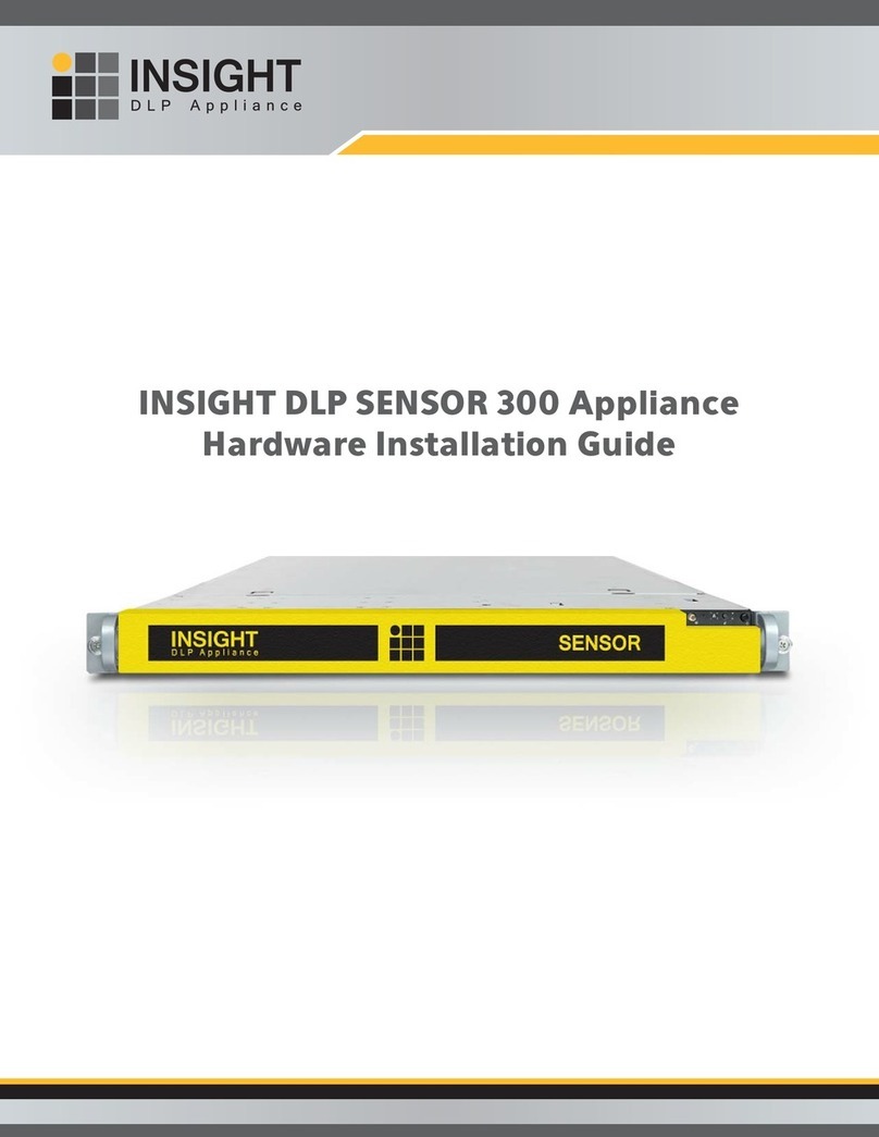
INSIGHT DLP SENSOR 310 Manual

INSIGHT DLP SENSOR 310, 310NTC & 310NTF
Appliance Hardware Installation Guide

INSIGHT DLP SENSOR 310, 310NTC & 310NTF Appliance Hardware Installation Guide www.insightdlp.com Page 2
Section 1 Safety Notice and Warnings . . . . . . . . . . . . . . . . . . . . . . . . . . . . . . . . . . . . . . . . . . . . . . . . . . .3
Section 2 Ratings . . . . . . . . . . . . . . . . . . . . . . . . . . . . . . . . . . . . . . . . . . . . . . . . . . . . . . . . . . . . . . . . . . . . . . 3
Section 3 Site Preparation . . . . . . . . . . . . . . . . . . . . . . . . . . . . . . . . . . . . . . . . . . . . . . . . . . . . . . . . . . . . . . 4
Section 4 Unpacking the 4-Post Rack Installation Assemblies . . . . . . . . . . . . . . . . . . . . . . . . . . . . . . . 5
Section 5A 4-Post Rack Installation with Standard Rails . . . . . . . . . . . . . . . . . . . . . . . . . . . . . . . . . . . . . 6
Section 5B 4-Post Rack Installation with Quick Mount Rails (square hole rack only) . . . . . . . . . . . . 7
Section 6 Installing the Appliance in the 4-Post Rack . . . . . . . . . . . . . . . . . . . . . . . . . . . . . . . . . . . . . . 8
Section 7 Unpacking the 2-Post Rack Installation Hardware . . . . . . . . . . . . . . . . . . . . . . . . . . . . . . . . 9
Section 8 2-Post Rack Installation . . . . . . . . . . . . . . . . . . . . . . . . . . . . . . . . . . . . . . . . . . . . . . . . . . . . . . . . 10
Section 9 Installing the Appliance in the 2-Post Rack . . . . . . . . . . . . . . . . . . . . . . . . . . . . . . . . . . . . . . 11
Section 10 Rear Panel Connections . . . . . . . . . . . . . . . . . . . . . . . . . . . . . . . . . . . . . . . . . . . . . . . . . . . . . . . 12
Section 11 Front Panel Operation . . . . . . . . . . . . . . . . . . . . . . . . . . . . . . . . . . . . . . . . . . . . . . . . . . . . . . . . . 14
Table of Contents

INSIGHT DLP SENSOR 310, 310NTC & 310NTF Appliance Hardware Installation Guide www.insightdlp.com Page 3
1. Safety Notice and Warnings
2. Ratings
FCC Notice
This device complies with part 15 of the FCC Rules. Operation is subject to the following two conditions:
1. This device may not cause harmful interference.
2. This device must accept any interference received, including interference that may cause
undesired operation.
No Telecommunications Network Voltage (TNV)-connected PCBs shall be installed.
CAN ICES-3 (A)/NMB-3(A)
CE Mark Warning
This is a Class A product. In a domestic environment, this product may cause radio interference,
in which case the user may be required to take adequate measures.
VCCI Warning
This is a product of VCCI Class A Compliance.
Environmental Warning
Perchlorate Material - special handling may apply.
See www.dtsc.ca.gov/hazardouswaste/perchlorate.
This notice is required by California Code of Regulations, Title 22, Division 4.5, Chapter 33: Best
Management Practices for Perchlorate Materials. This product/part includes a battery that contains
perchlorate material.
AC input voltage: 100 - 240 V (auto-range)
Input frequency range: 50/60 Hz
Rated input current: 100 - 140V 8.0/6.0A
200 - 240V 4.5/3.8V

INSIGHT DLP SENSOR 310, 310NTC & 310NTF Appliance Hardware Installation Guide www.insightdlp.com Page 4
Setup location, rack and appliance precautions
nElevated Operating Ambient Temperature - If installed in a closed or multi-unit rack assembly, the
operating ambient temperature of the rack environment may be greater than room ambient. Therefore,
consideration should be given to installing the equipment in an environment compatible with the maximum
ambient temperature (Tma) specified by the manufacturer.
Always keep the rack’s front door and all panels and components on the appliances closed when not
servicing to maintain proper cooling.
nReduced Air Flow - Installation of the equipment in a rack should be such that the amount of air flow
required for safe operation of the equipment is not compromised. Leave enough clearance, approximately
25 inches in the front, and 30 inches in the back of the rack to enable you to access appliance components
and allow for sufficient air flow.
nMechanical Loading - Mounting of the equipment in the rack should be such that a hazardous condition
is not achieved due to uneven mechanical loading.
ALL RACKS MUST BE MOUNTED SECURELY.
Ensure that all leveling jacks or stabilizers are properly
attached to the rack. If installing multiple appliances in a rack, make sure the overall loading for each
branch circuit does not exceed the rated capacity.
Do not slide more than one appliance out from the rack at a time. Extending more than one appliance at a
time may result in the rack becoming unstable. Install your appliance in the lower part of the rack because
of its weight and also for ease in accessing appliance components.
nCircuit Overloading - Consideration should be given to the connection of the equipment to the supply
circuit and the effect that overloading of the circuits might have on overcurrent protection and supply
wiring. Appropriate consideration of equipment nameplate ratings should be used when addressing this
concern.
nReliable Earthing - Reliable earthing of rack-mounted equipment should be maintained. Particular
attention should be given to supply connections other than direct connections to the branch circuit
(e.g. use of power strips).
Install near appropriate AC outlets, and Ethernet hubs or individual jacks. Be sure to install an AC Power
Disconnect for the entire rack assembly. The Power Disconnect must be clearly marked. Ground the rack
assembly properly to avoid electrical shock.
3. Site Preparation

Rack rail assembly, outside view
Rack rail assembly, inside view
Adjustable front rack rail assembly
(attaches to the front of the rack)
Adjustable rear rack rail assembly
(attaches to the rear of the rack)
INSIGHT DLP SENSOR 310, 310NTC & 310NTF Appliance Hardware Installation Guide www.insightdlp.com Page 5
Quick-mount rack rail assembly, inside view
Quick-mount rack rail assembly, outside view
Adjustable front quick-mount rack rail assembly
(attaches to the front of the rack)
Adjustable rear quick-mount rack rail assembly
(attaches to the rear of the rack)
4. Unpacking the 4-Post Rack Installation Assemblies
Verify that the ship kit includes one of the following installation assemblies
Installation Assembly A: Standard Rail Assemblies with
Mounting Hardware
nTwo power cords*
nA set of 4-post rack mounting hardware**
nA pair of 4-post rack sliding chassis rail rack assemblies that attach directly to the rack
Installation Assembly B: Quick Mount Rails (for use in 4-post racks with square holes only)
nTwo power cords*
nTwo 10-32 x 3/4” Phillips pan head screws**
nA pair of adjustable quick-mount rack rail assemblies (requires no additional mounting hardware or tools)
(Two) 10-32 x 3/4”
Phillips pan head screws
(used to secure the appliance in the rack)
(Eight) M5 x 12
Phillips flat head screws
(Two) 10-32 x 3/4”Phillips pan head screws
(used to secure the appliance in the rack)
(Eight) M5 x 12
cone washers
(Ten) M5
cage nuts
NOTE: Use the hardware
supplied with your specific
rack if different from the
hardware supplied in this kit.
NOTE: Only two power cords
will be included in your
ship kit even if you receive
multiple rail kits.
NOTE: There may be
additional mounting
hardware included that will
not be used with this
installation assembly kit.
**
*

INSIGHT DLP SENSOR 310, 310NTC & 310NTF Appliance Hardware Installation Guide www.insightdlp.com Page 6
Adjustable rack rail assemblies
4-post rack
Empty
hole
Empty
hole
Empty
hole
Rear section of
the adjustable
rack rail assembly
Rack bracket tab
Rack bracket tabs
Front section of
the adjustable
rack rail assembly
5A. 4-Post Rack Installation with Standard Rails
Locate the mounting hardware and rack rail assemblies shown below
Step 2
nInsert a cage nut into each of the
square holes in the rack you will be
using as shown (three in the front
and two in the rear). They click into
place.
nAttach the rack /rail assemblies to
the rack using two M5 x 12 flat head
screws and cone washers in the front
and back. The convex side of the cone
washers face toward the rack.
nMake sure the rack / rail assemblies
and screws are aligned in the rack
not only in the front and back, but
are level in height on the left and
right sides for proper alignment for
appliance installation.
Step 1
Locate the two adjustable standard rack
rail assemblies.
nInsert the tabs on the front section of
the adjustable rack rail assembly through
the openings in the rear sections of the
assemblies.
nCheck to make sure the adjustable rack
rail assemblies are connected correctly,
then slide the front section forward and
the rear section back to keep them from
coming apart. These assemblies adjust
to accommodate different rack depths.
NOTE: The installation
procedures for Sections 6A
and 6B, 4-Post Rack, below
and on page 9 are for use
with the rails and hardware
provided in your ship kit. If
different style rails are being
used, or if your rack requires
different hardware, refer to
the instructions provided with
your rail’s or rack’s ship kit.

INSIGHT DLP SENSOR 310, 310NTC & 310NTF Appliance Hardware Installation Guide www.insightdlp.com Page 7
5B. 4-Post Rack Installation with Quick Mount Rails (square hole rack only)
Locate the quick mount rack rail assemblies shown below
Rear section of
the adjustable
rack rail assembly
Rack bracket tab
Rack bracket tabs
Front section of
the adjustable
rack rail assembly
Step 1
Locate the two adjustable quick-mount
rack rail assemblies.
nInsert the tabs on the front section of the
adjustable rack rail assembly through the
openings in the rear sections of the assemblies.
nCheck to make sure the adjustable rack rail
assemblies are connected correctly, then slide
the front section forward and the rear section
back to keep them from coming apart. These
assemblies adjust to accommodate different
rack depths.
Quick-mount
locking
mechanism
Adjustable quick-mount
rack rail assemblies
Empty
hole
Empty hole
Quick-mount
rail tabs
(angle view)
Quick-mount
rail tabs
(side view) Quick-mount rail
locking mechanism
4-post
rack
D
C
E
A
B
Step 2
nQuick-mount rail Installation in the
square hole rack:
A. Insert the quick-mount rail tabs
on the front of the rack rail
assembly through the selected
set of square holes in the rack.
B. Push the tabs into the holes in the rack
until you hear the locking mechanism
on the rail assembly click into place.
The locking mechanism secures the rails
to the rack.
C. Slide the rail assembly to the back of
the rack.
D. In the rear, insert the quick-mount rail tabs
through the square holes level with the front
installation.
E. Push the tabs into the holes until you hear
the rear locking mechanism click into place.
nRepeat these steps for the other side of the rack.*
NOTE: Make sure the quick-mount rail assemblies are
aligned in the rack not only in the front and back, but
are level in height on the left and right sides for proper
alignment for appliance installation.
NOTE: There is a threaded hole between
the two quick-mount tabs in the rail
assembly. This hole will be used to
secure the appliance in the rack later
in this guide.
*

Adjustable rack rail assemblies
(standard or quick-mount)
Fixed chassis rail
(attached prior to shipment)
Locking tab
Two 10-32 x 3/4”
Phillips flat-head screws*
INSIGHT DLP SENSOR 310, 310NTC & 310NTF Appliance Hardware Installation Guide www.insightdlp.com Page 8
6. Installing the Appliance in the 4-Post Rack
nAlign the inner fixed chassis rails on the appliance with the fixed chassis rack rail assemblies previously
installed in the rack.
nCarefully slide the appliance into the rack rails until you hear the locking tabs on the chassis rails click
into place.
nPush the appliance all the way into the rack until it stops.
nSecure the unit in the rack by inserting and tightening two 10-32 x 3/4” Phillips pan head screws,
one on each side.
NOTE: When removing the
appliance from your rack, you
will need to press down on the
locking tab in order to release
it from the rack. Carefully
slide it out supporting the
unit on both sides at all times.

INSIGHT DLP SENSOR 310, 310NTC & 310NTF Appliance Hardware Installation Guide www.insightdlp.com Page 9
4 (Four)
Fixed 2-post rack brackets
Inside front view Outside front view
2 (Two)
Fixed 2-post rack brackets
with threaded holes
Inside front view Outside front view
7. Unpacking the 2-Post Rack Installation Hardware
Verify that the ship kit includes the following installation hardware
Installation Hardware
nTwo power cords*
nA set of 2-post rack mounting hardware**
nTwo pairs of 2-post rack mounting brackets
nA pair of 2-post rack mounting brackets with threaded holes
nA pair of 2-post rack assemblies that attach directly to the rack
2 Post Rack rail assembly, outside view
2 Post Rack rail assembly, inside view
(Eight) M5 x 12
Phillips flat head screws
(Two) 10-32 x 3/4”
Phillips pan head screws
(used to secure the appliance in the rack)
(Twenty-two) M4 x 4
Phillips truss head screws
NOTE: Use the hardware
supplied with your specific
rack if different from the
hardware supplied in this kit.
NOTE: Only two power cords
will be included in your
ship kit even if you receive
multiple rail kits.
NOTE: There may be
additional mounting
hardware included that will
not be used with this
installation assembly kit.
**
*

Small fixed
rack brackets
Long bracket
C
B
C
Two M4 truss head screws
One M4 truss
head screw
BSmall fixed
rack brackets
Small fixed
rack brackets with
threaded holes
A
A
INSIGHT DLP SENSOR 310, 310NTC & 310NTF Appliance Hardware Installation Guide www.insightdlp.com Page 10
M5 x 12 flat
head screws*
(two front and
two rear)
A
A
A
A
B
B
8. 2-Post Rack Installation
Unpack the appliance and locate the mounting hardware
Step 1
Locate the two long and six short rack
brackets that came in your ship kit.
A. Securely attach the set of short brackets
with the threaded screw holes to the
long bracket in the front as shown.
Use two M4 truss head screws for each
bracket.
B. Loosely attach one set of the other short
brackets to the long fixed bracket as
shown using one M4 truss head screw on
each bracket. The three holes on the flap
will face toward the back for later
attachment to the 2-post rack.
C. Loosely attach the remaining set of short
brackets to the long fixed bracket as
shown using one M4 truss head screw
on each bracket. The three holes on the
flap will face toward the front for later
attachment to the 2-post rack.
Step 2
Attach the assembled brackets to the
2-post rack.
A. Insert two M5 x 12 flat head screws
through the short brackets into the
2-post rack (in the front and back of the
rack as shown) and tighten. Make sure
the brackets are aligned and level in
height, not only in the front and back
but also on the left and right sides.
B. Tighten each of the single screws on the
small fixed brackets (located on either side
of the rack) to secure the brackets in the
rack and ensure appliance stability.
NOTE: Once the assembled rails
are attached to the rack, securely
tighten the single screws on steps
Band C.
NOTE: The following installation
procedures for Section 9, 2-Post
Rack are for use with the rails and
hardware provided in your ship
kit. If different style rails are being
used, or if your rack requires
different hardware, refer to the
instructions provided with your
rail’s or rack’s ship kit.

INSIGHT DLP SENSOR 310, 310NTC & 310NTF Appliance Hardware Installation Guide www.insightdlp.com Page 11
Two 10-32 x 3/4”
Phillips flat-head screws*Fixed chassis rail
(attached prior to shipment)
Locking tab
9. Installing the Appliance in the 2-Post Rack
nAlign the inner fixed chassis rails on the appliance with the fixed chassis rack rail assemblies previously
installed in the rack.
nCarefully slide the appliance into the rack rails until you hear the locking tabs on the chassis rails click
into place.
nPush the appliance all the way into the rack until it stops.
nSecure the unit in the rack by inserting and tightening two 10-32 x 3/4” Phillips pan head screws,
one on each side.
NOTE: When removing the
appliance from your rack, you
will need to press down on the
locking tab in order to release
it from the rack. Carefully
slide it out supporting the
unit on both sides at all times.

INSIGHT DLP SENSOR 310, 310NTC & 310NTF Appliance Hardware Installation Guide www.insightdlp.com Page 12
10. Rear Panel Connections
A C
L
M
N T U V W
O
P
Q
R
S
B ID
F GE H
K
JAC FEGHJ
L
M
B
NT
O
P
Q
R
S
D
UV W
IK
A
B
C
D
E
F
G
H
I
J
K
Power Supply Module #1
AC Power Inlet #1
Power Supply #2
AC Power Inlet #2
COM Port
Remote Management Port
Low Profile PCIe Expansion Slot
eth3 Port
DLP Port
SPAN Port
MGMT Port
L
M
N
O
P
Q
R
S
T
U
V
W
Power Good LED #1
Power Supply Lock #1
Power Good LED #2
Power Supply Lock #2
USB Port 1 (generation 2)
USB Port 2 (generation 2)
USB Port 3 (generation 3)
USB Port 4 (generation 3)
eth4 Port
eth5 Port
VGA Port
RAID Controller Card
CAUTION
Slide rail/mounted equipment
is not to be used as a shelf or a
work space.

1
1
3
1
3
1
1
INSIGHT DLP SENSOR 310, 310NTC & 310NTF Appliance Hardware Installation Guide www.insightdlp.com Page 13
10. Rear Panel Connections (continued)
Step 1 Connect the Ethernet cables.
Step 2 Connect any other required cables.
Step 3 Connect the power cords.
Proceed to Section 12, Front Panel Operation on page 14.
Power Supply Condition
Output ON and OK
No AC power to both power supplies
AC present / Only 5VSB on (PS off)
AC cord unplugged or AC power lost; with
a second power supply in parallel still with
AC input power
Power supply warning events where the
power supply continues to operate; high
temp, high power, high current, slow fan
Power supply critical event causing a
shutdown; failure, OCP, OVP, fan fail
LED State
GREEN
OFF
AMBER
OFF
1Hz Blinking
AMBER
AMBER
In normal operation the Power Good LED on Power Supply
Module 1 and Module 2 will be SOLID GREEN. If the power is
down, both LEDs will BLINK GREEN.
Power Supply Status LED
There is a single bi-color Power Good LED on each power
supply module to indicate power supply status. The LED
operation is defined in the table below.
NOTE: The server offers redundant, hot-swap capability.
The connections to AC mains should be made in a
manner appropriate to local code and consistent with
customer power distribution with or without redundant
sources.
CAUTION
The power supply is hot-swappable only when you have
a server with redundant power supplies installed. If you
only have one power supply installed, before removing
or replacing the power supply, you must first take the
server out of service, turn off all peripheral devices
connected to the server, turn off the server by pressing
the power button, and unplug the AC power cord from
the server or wall outlet.

INSIGHT DLP SENSOR 310, 310NTC & 310NTF Appliance Hardware Installation Guide www.insightdlp.com Page 14
21
UID
21
UID
Multi-function LED
Blue LED
System identification
indicator
Red LED
System alert
indicator
NIC1 LED Power LED
I/O Power
Button
Unit ID Button
HDD LEDNIC2 LED
2
11
2
1
ED
IC1 L
N
e
Power LED
2
D
LED
IC2
NEDL
D
HD
Multi-function LED
oricatind
entificationSystem id
Blue LED
icatorind
System alert
LEDRed
n
Button
Unit ID
uttonB
/O PowerI
11. Front Panel Operation
Power on the appliance
nRemove the front bezel (if it is on the
appliance) by pressing in on the left side of
the bezel to release it from the appliance.
nPress the power button located on the far
right on the front side of the appliance.
nOnce the system has been powered on,
replace the bezel.
Copyright ©2017 Insight DLP. All rights reserved.
2900 South Quincy Street
Suite 330
Arlington, VA 22206
877-610-5625
877-605-8482 (F)
www.insightdlp.com
This manual suits for next models
2
Table of contents
Other INSIGHT Network Hardware manuals
