Insoric RealPower Parts list manual

© Copyright 2016 by Insoric AG
Insoric RealPower
Technical description

Insoric RealPower / 10.06.2016 2 / 34
Dear valued customer
By purchasing Insoric RealPower you have acquired a high-quality product distinguished by special
capabilities and permanent innovation in the field of performance measurement. Congratulations on your
purchase of this high-quality product and thank you for your trust.
The Insoric Team
Imprint
This instruction manual is a publication by Insoric AG, Hofwisenstrasse 12,
CH-8260 Stein am Rhein, Switzerland / Tel. +41(0)52 742 04 40 / info@insoric.com / www.insoric.com.
The instruction manual is part of the Insoric RealPower measuring system. It contains important information
on commissioning, handling and operation. In order to ensure proper and safe operation, all instructions
must be precisely followed. The same applies if you pass on the product to third parties.
All rights, including translation, are reserved. Duplication of any kind whatsoever such as photocopying,
microfilming or recording on electronic data processing systems requires the written permission of the
publisher. Reproduction in whole or in part is prohibited.
This instruction manual reflects the technical status at the time of going to print. Later changes that are not
included in the instruction manual and further guidance and assistance can be found on our website at
www.insoric.com.

Insoric RealPower / 10.06.2016 3 / 34
Contents
1.0 Technical description ............................................................................................................. 4
1.1 Recording power data........................................................................................................................ 4
1.2 Analysing the data ............................................................................................................................. 4
1.3 Product specifications........................................................................................................................ 5
1.4 Controls and indicators - RealPower Module..................................................................................... 6
1.5 Switch functions ................................................................................................................................ 6
1.6 LED indicators .................................................................................................................................... 6
1.7 Software............................................................................................................................................. 7
1.8 Licence key......................................................................................................................................... 7
2.0 Operating instructions ........................................................................................................... 8
2.1 Safety instructions ............................................................................................................................. 8
2.1.1 Safety warnings - Definition ..................................................................................................................8
2.1.2 Safety warnings - General rules .............................................................................................................8
2.2 Using for the first time....................................................................................................................... 9
2.2.1 Installing RealPower software and driver ...............................................................................................9
2.2.2 Charging the battery.............................................................................................................................9
2.3 Preparing for the road test ................................................................................................................ 9
2.3.1 Road test route ....................................................................................................................................9
2.3.2 Attaching the RealPower module .........................................................................................................10
2.3.3 Activating the RealPower module.........................................................................................................11
2.4 The road test .................................................................................................................................... 11
2.4.1 Vehicle safety.....................................................................................................................................11
2.4.2 Road test safety .................................................................................................................................11
2.4.3 Road test - Power measurement .........................................................................................................12
2.5 After the road test............................................................................................................................ 13
2.5.1 Removing the RealPower module ........................................................................................................13
2.6 Preparing for analysis ...................................................................................................................... 13
2.6.1 Preparing the data.............................................................................................................................. 13
2.6.2 Measuring the wheel diameter ............................................................................................................14
2.7 Analysing the data ........................................................................................................................... 14
2.7.1 Starting the RealPower software..........................................................................................................14
2.7.2 Entering basic settings ........................................................................................................................15
2.7.3 Reading the data from the RealPower module ........................................................................................9
2.7.4 Analysing the results........................................................................................................................... 20
2.7.4.1 Entering parameters ................................................................................................................... 20
2.7.4.2 Marking the acceleration and roll areas ........................................................................................ 23
2.7.4.3 V mark.......................................................................................................................................27
2.7.4.4 Displaying the measurement results............................................................................................. 28
2.7.4.5 Freezing the power diagram ........................................................................................................ 29
2.7.5 Producing a test certificate..................................................................................................................30
2.7.6 Saving the measurement results..........................................................................................................32
2.7.7 Opening measurement results ............................................................................................................. 32
2.7.8 User Informations...............................................................................................................................33
3.0 General instructions............................................................................................................. 34
3.1 Maintenance and cleaning ............................................................................................................... 34
3.2 Rectifying errors and faults ............................................................................................................. 34
3.3 Technical data .................................................................................................................................. 34
3.4 Disposal............................................................................................................................................ 34

Insoric RealPower / 10.06.2016 4 / 34
1.0 Technical description
1.1 Recording power data
Insoric RealPower enables precise measurement of vehicle performance.
The readings are taken from the vehicle's road wheel.
All data produced during a road test is recorded and
internally stored by the RealPower module attached to
the vehicle wheel.
1.2 Analysing the data
Using the RealPower software specially developed for this application, analysing the data is simple.
After a road test and having installed the RealPower software, you
connect the RealPower module to your PC using a USB lead.
You can then enter various parameters relating to a road test and
save vehicle-related details in the RealPower program. There are
also functions for selecting individual measurement results and
producing test certificates for them.
The use of the RealPower module and the subsequent data analysis on a PC do not require any kind of
specialist knowledge. Consequently, a key feature of the product is that it can be used immediately without
knowing the specifications of the vehicle being tested.
The following performance data can be measured with the Insoric RealPower system:
Wheel power
Engine power
Road speed
Maximum torque
Insoric RealPower / 10.06.2016 5 / 34
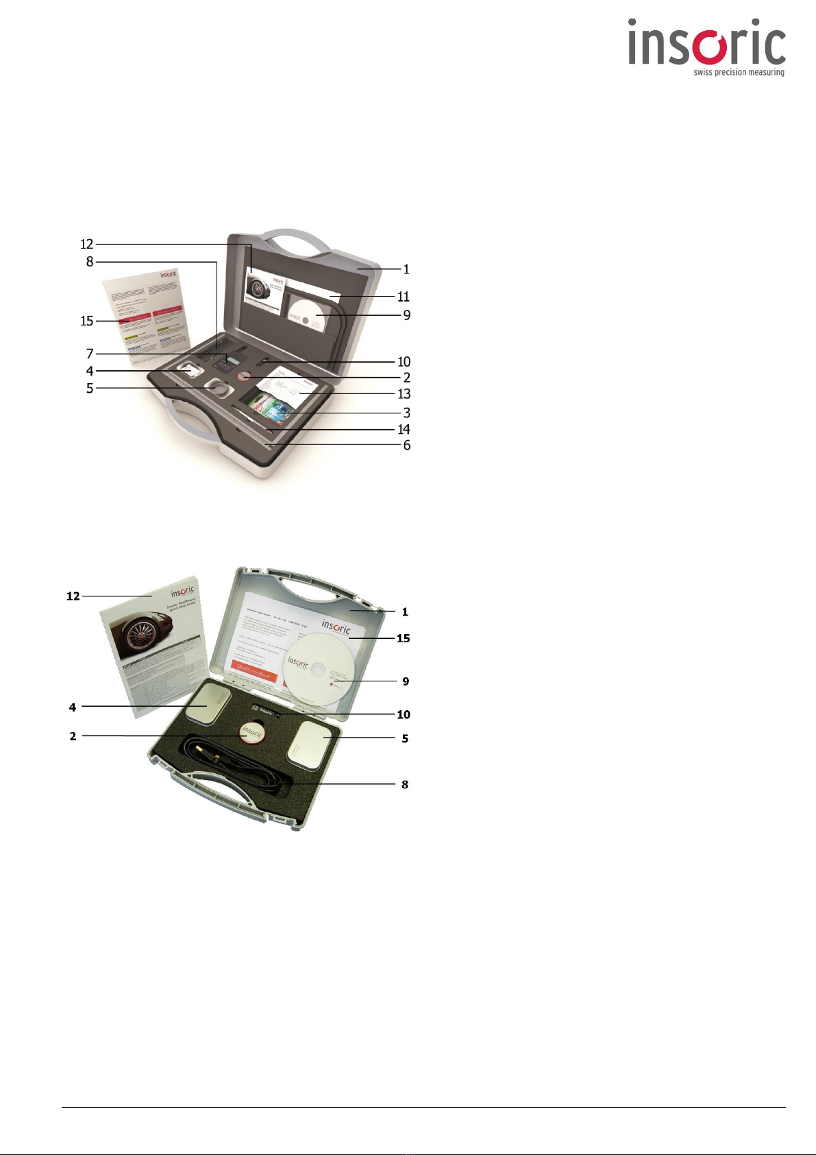
1.3 Product specifications
The measuring system and all required accessories are supplied in a case.
RealPower Dyno-System Professionell
1 Case
2 RealPower module
3 Fixing systems
4 Canister with fixing systems
5 Canister with protective cap
6 Wheel measuring device
7 Barometer/Thermometer
8 USB lead
9 Installation CD/DVD
10 USB Stick (licence key)
11 Instruction manual
12 Quick step guide
13 Data checklist
14 Ball-point pen
15 Quality certificate/Safety instructions
RealPower Dyno-System Basic / RealPower Dyno-System Premium
This product left our factory in perfect condition. Please check the case after receipt for any
damage and to make sure nothing is missing, and inform us immediately if anything is not as it
should be.
To maintain proper working order of the product and ensure trouble-free operation of Insoric RealPower, it is
imperative that you follow the directions in this instruction manual.
Use for purposes other than that described in the instruction manual may impair or damage the product.
Insoric RealPower must not be modified or converted as doing so will void the manufacturer's guarantee.

Insoric RealPower / 10.06.2016 6 / 34
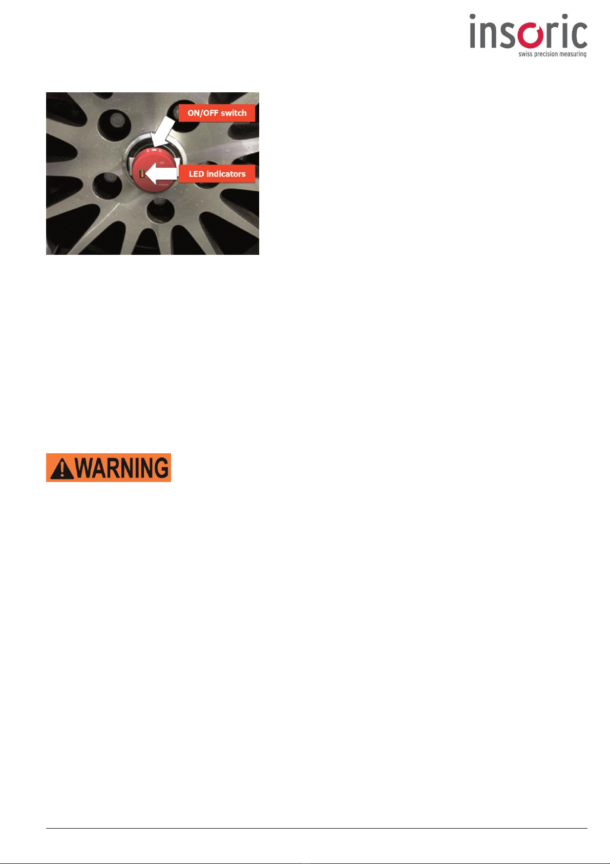
1.4 Controls and indicators - RealPower Module
1Green LED –ON mode
2Orange LED –Recording mode
3Red LED –Charging battery mode
4Yellow LED –Error mode
5USB socket
6RealPower module "ON/OFF"
and mode selector button
1.5 Switch functions
Switching on the RealPower module –ON mode
Press and hold the ON/OFF button (for 1 sec) ð The RealPower module is now activated (green "ON" LED
flashes).
Starting recording –Recording mode
Press and hold the ON/OFF button again (for 1 sec) ð The RealPower module switches to recording mode
(green "ON" LED and orange "RECORD" LED both flash).
Stopping recording
Press and hold the ON/OFF button (for 1 sec) ð The RealPower module switches back to ON mode (green
"ON" LED flashes).
Switching off the RealPower module
Press and hold the ON/OFF button (for 3 sec) ð The RealPower module is now deactivated (no LEDs
flashing).
1.6 LED indicators
Green "ON" LED –ON mode
Signals by flashing that the RealPower module is switched on.
Orange "RECORD" LED –Recording mode
Signals by flashing in alternation with the green "ON" LED that the RealPower module is in recording mode.
If the "RECORD" LED remains constantly lit, it indicates that the recording capacity of the RealPower
module has reached its limit (the maximum recording capacity is 80 minutes). The RealPower module
memory then has to be cleared using the RealPower software application before further road tests can be
carried out.
Red "CHARGE" LED –Charging battery mode
When constantly lit, signals that the internal battery is being charged (only when the RealPower module is
connected to a PC by the USB lead).
Yellow "ERROR" LED –Error mode
Signals an error. If the yellow LED does not go out after the RealPower module is switched off and on again,
please contact the manufacturer via the website www.insoric.com/support.

Insoric RealPower / 10.06.2016 7 / 34
If the "RECORD" LED remains constantly lit, it indicates that the recording capacity of the RealPower
module has reached its limit (the maximum recording capacity is 80 minutes). The RealPower module
memory then has to be cleared using the RealPower software application before further road tests can be
carried out.
1.7 Software
Supplied with the product, there is an installation CD/DVD containing the RealPower software for analysing
the recorded power data. The RealPower software requires a special driver which is also supplied on the
installation CD/DVD. Please note the following basic and system requirements for using the RealPower
software:
Basic requirements:
DVD-ROM drive
2 available USB ports
Printer (preferably a colour printer)
Keyboard
Mouse with scrolling wheel
System requirements:
Microsoft®Windows 7, 8, 10
At least 1 GB of RAM
Hard disk with at least 2 GB of free space
Graphics card with min. resolution of 1024 x 768
Adobe Acrobat Reader®
1.8 Licence key
To use Insoric RealPower you require a licence issued by Insoric. That licence is supplied with the product in
the form of a USB stick, i.e. there is a licence key stored on the USB stick. To be able to use the RealPower
software, the USB stick must be plugged into your PC –otherwise an error message will be displayed.
You can install the RealPower software on multiple PCs. However, the program will only run in conjunction
with the licence key. If you lose the licence key, you will not be able to start the RealPower software.
The licence key controls the range of functions available in the RealPower software and the number of
power tests that you have available.

Insoric RealPower / 10.06.2016 8 / 34
2.0 Operating instructions
2.1 Safety instructions
2.1.1 Safety warnings –Definition
This warning indicates a potentially dangerous situation that could lead to serious
or fatal injuries if the safety precautions are not followed.
This warning indicates a potentially dangerous situation that could lead to minor
or slight injuries if the safety precautions are not followed.
This warning indicates the possibility of damage to property if the safety
precautions are not followed.
Special tips that can simplify working with Insoric RealPower are printed in
Italics
.
With the exception of the instructions given in Section 2.1.2, the safety warnings appear next to the
passage of text to which they relate.
2.1.2 Safety warnings - General rules
Before using Insoric RealPower for the first time, please read through the whole of the instruction manual as
it contains all the important information for correct operation.
Operation of the Insoric RealPower measuring system is at the user's own risk. We accept no liability for
personal injury or damage to property caused by incorrect use or failure to follow the safety instructions. In
such cases all guarantee entitlement will also be void.
The RealPower module casing must not be opened nor its contents interfered with or modified. In such
cases all guarantee entitlement will be void.
The applicable statutory road traffic regulations and highway code of the country in which the Insoric
RealPower is used must be observed. Compliance with those regulations is the responsibility of the user
alone.
When using Insoric RealPower in schools or educational establishments, supervision by trained technical
staff is absolutely imperative.
The RealPower module and its accessories are not toys and should not be operated by children!
The statutory safety regulations for prevention of road traffic accidents are to be observed.

Insoric RealPower / 10.06.2016 9 / 34
2.2 Using for the first time
2.2.1 Installing RealPower software and driver
After inserting the CD/DVD in the DVD drive of your PC, the installation menu for the software and driver will
automatically open.
The RealPower software is not a network application. Therefore please install the software on your hard
drive.
If the installation screen does not automatically open, you can start it manually by double-clicking the file
autorun.exe, which is on the CD/DVD.
Make sure that the driver is correctly installed on your PC. That is the only way that communication between
the RealPower software and the RealPower module is possible.
2.2.2 Charging the battery
Before using the RealPower module for the first time and/or before the first road test, its battery must be
charged. That is done using only the USB lead supplied.
Connect the USB lead to the RealPower module and a free USB port on the PC. The first time it is charged,
the RealPower module should remain connected until the red "CHARGE" LED goes out (see also Section
1.6).
The RealPower module can be charged on any PC that has a USB port.
Risk of property damage
Only connect the RealPower module to a USB port on a PC. That is the only way
to ensure it is charged at the correct voltage.
If the electronics of the RealPower module are damaged due to charging the
battery incorrectly guarantee will be void.
2.3 Preparing for the road test
2.3.1 Road test route
To measure the power, acceleration or torque on a vehicle, a suitable road test route is required. Ideally,
the course of the road should contain no uphill or downhill gradients or corners and should be at least 800
m long. The route should provide clear visibility along its entire length and allow a speed of at least 80 kph.

Insoric RealPower / 10.06.2016 10 / 34
2.3.2 Attaching the RealPower module
To carry out a road test, the RealPower module has to be attached to the wheel of the vehicle being tested.
There are fixing systems supplied with the product for the purpose.
Risk of accidents and property damage
If the RealPower module were to become detached from the wheel during the
road test it would pose a danger to other road users.
In addition, the RealPower module could be destroyed.
Use only the fixing systems supplied by the manufacturer.
Risk of dirt: the wheel must be cleaned using a dirt and grease removing
cleaner before attaching the RealPower module. Do not use cleaners that are
corrosive or contain solvents.
Risk of moving parts and wheel trims: the RealPower module must not be
attached to moving parts of the wheel, wheel trims or hub caps that could
become detached when the vehicle is moving.
Risk of uneven attachment face: wheels with an uneven or ridged centre
are not suitable for attaching the RealPower module. The attachment face
must be completely flat.
Risk of eccentricity: the RealPower module must be attached exactly in the
centre of the wheel.
When carrying out the road test avoid extreme weather conditions such
as heavy rain, hail showers or heavy snow falls.
Risk of property damage
There is a risk of damage to the RealPower module from splash-water
or dirt in bad weather.
Attach the protective cap supplied to the RealPower module.
As a fundamental principle, the RealPower module should always be fixed on the passenger side. To
counteract the spin that can occur on a driving wheel, it should be attached to a non-driven wheel. (Check
whether car is front or rear-wheel drive!)
For cars with four-wheel drive it doesn't matter whether the module is attached on the front passenger side
or rear passenger side.
Attaching the RealPower module is very easy: remove the
protective foil from one side of the fixing system and fix it to
the back of the RealPower module
(the side with the Insoric
logo).
In that way, the LED indicators remain clearly visible.
Then remove the protective foil from the other side of the
fixing system and press the RealPower module as exactly as
possible onto the centre of the wheel.
The RealPower module is not designed for continuous use and
must be removed from the wheel again after completing the
road test.
Insoric RealPower / 10.06.2016 11 / 34
2.3.3 Activating the RealPower module
Switch on the RealPower module before starting the road test.
To do so, press the "ON/OFF" button twice in succession.
The RealPower module is now in recording mode.
The orange "RECORD" LED flashes in alternation with the "ON"
LED.
Please note that the recording capacity of the module memory
is 80 minutes. If the RealPower module has already been used
before, we recommend that you delete the module data before
each new road test (see Section 2.7.3).
If the recording capacity limit is reached during a road test, the RealPower module automatically switches
off and no further data is recorded. In that case, the data has to be read out and the memory cleared as
described in Section 2.7.3 before the RealPower module can be used again.
2.4 The road test
2.4.1 Vehicle safety
Before commencing the road test, the vehicle must be checked for roadworthiness and/or damage that
might impair its handling characteristics and road safety.
Risk of accidents
There is a risk of accidents if tyres are not inflated to the correct pressure or
are worn or damaged.
Check the tyre pressure and examine the tyres for damage and penetration
by foreign objects.
Incorrectly adjusted tyre pressure affects the wheel diameter and, therefore, also the measurement results.
2.4.2 Road test safety
Use of this product is at your own risk. Inadequate attachment of the RealPower module and incorrect use
of Insoric RealPower are the responsibility of the user.
During the road test, the general statutory road safety regulations apply.
When performing the road test, always keep within the legally permitted speed limit. Desist from extreme
and risky driving manoeuvres.

Insoric RealPower / 10.06.2016 12 / 34
Risk of accidents
An unsuitable choice of road test route could place you and other road users
at risk.
Do not continue with the road test if the circumstances or the road or
weather conditions are not suitable.
Avoid routes with
heavy traffic
obscured visibility
junctions or crossroads
agricultural traffic
steep downhill gradients
Do not carry out road tests on roads
where children are playing
through built-up areas
with poor road surfaces
with snow or ice on the surface
with poor visibility due to fog or darkness
Discontinue the road test if any of the above circumstances occurs unexpectedly.
2.4.3 Road test - Power measurement
Before the road test, switch off air conditioning and other equipment and vehicle functions that affect
engine power.
The test involves two stages. Depending on the prevailing traffic conditions, the two stages (acceleration
and roll) can be carried out in a single run or separately with an interval in between.
Power measurement using Insoric RealPower consists of an acceleration phase followed by a roll phase.
During the acceleration phase, a power curve is recorded up to maximum revs. During the roll phase, the
vehicle-specific loss factors are recorded.
Road Test
Depending on vehicle power, the acceleration phase is carried out in 3rd or 4th gear.
Ideally, the acceleration phase should start at approx. 1500 rpm. Now press the accelerator to the floor
and accelerate the car until the rev counter needle reaches the red area, respectively the shift point if
using an automatic gearbox.
Make a mental note of the engine speed reached!
Legally permitted speed
Be sure to observe the allowed maximum speed for the road you are driving on.

Insoric RealPower / 10.06.2016 13 / 34
After that, you disengage the clutch so that the vehicle is rolling. You should leave the gear lever in the
gear previously selected. If using an automatic gearbox, select neutral if possible.
If it is not possible change to the neutral position, select the highest gear while rolling and take the foot of the throttle.
The roll phase should –allowing for the conditions on the road test route –last as long as possible. The
speed difference between declutching and the end of the roll phase should ideally be at least 30 km/h.
Several acceleration and rolling phases can also be carried out in succession. Combining multiple test phases
provides for greater possibilities when subsequently analysing the power data.
2.5 After the road test
2.5.1 Removing the RealPower module
After completing the road tests, the RealPower module should be switched off using the "ON/OFF" switch
(press and hold for approx. 3 sec) and removed from the wheel as follows:
Pull on the tab of the fixing system between the RealPower module and the wheel for several seconds
lengthwise. The RealPower module can then be removed easily from the wheel without using force.
Afterwards, remove the fixing system from the RealPower module.
The RealPower module is not designed for continuous use and must be removed from the wheel after
completing the road test. Use only fixing systems recomended by Insoric AG. Use fixing systems once only.
Risk of accidents and property damage
Using the fixing systems more than once could endanger other road users
if the RealPower module were to become detached from the wheel during
the road test. In addition, the RealPower module could be destroyed.
2.6 Preparing for analysis
2.6.1 Preparing the data
To calculate the power data ("maximum levels" and "performance diagram") and to produce the test
certificate, the RealPower software requires the following additional data:
Details from the car documents (registration certificate and owner's manual)
Wheel diameter (see Section 2.6.2)
Gear and maximum revs (details noted by the driver during the road test)
Meteorological data at the time of the road test (barometer/thermometer, see Section 1.3, item 7)
A "Data checklist" is supplied with the product to simplify the process of completing the data to be entered
manually.
Insoric RealPower / 10.06.2016 14 / 34
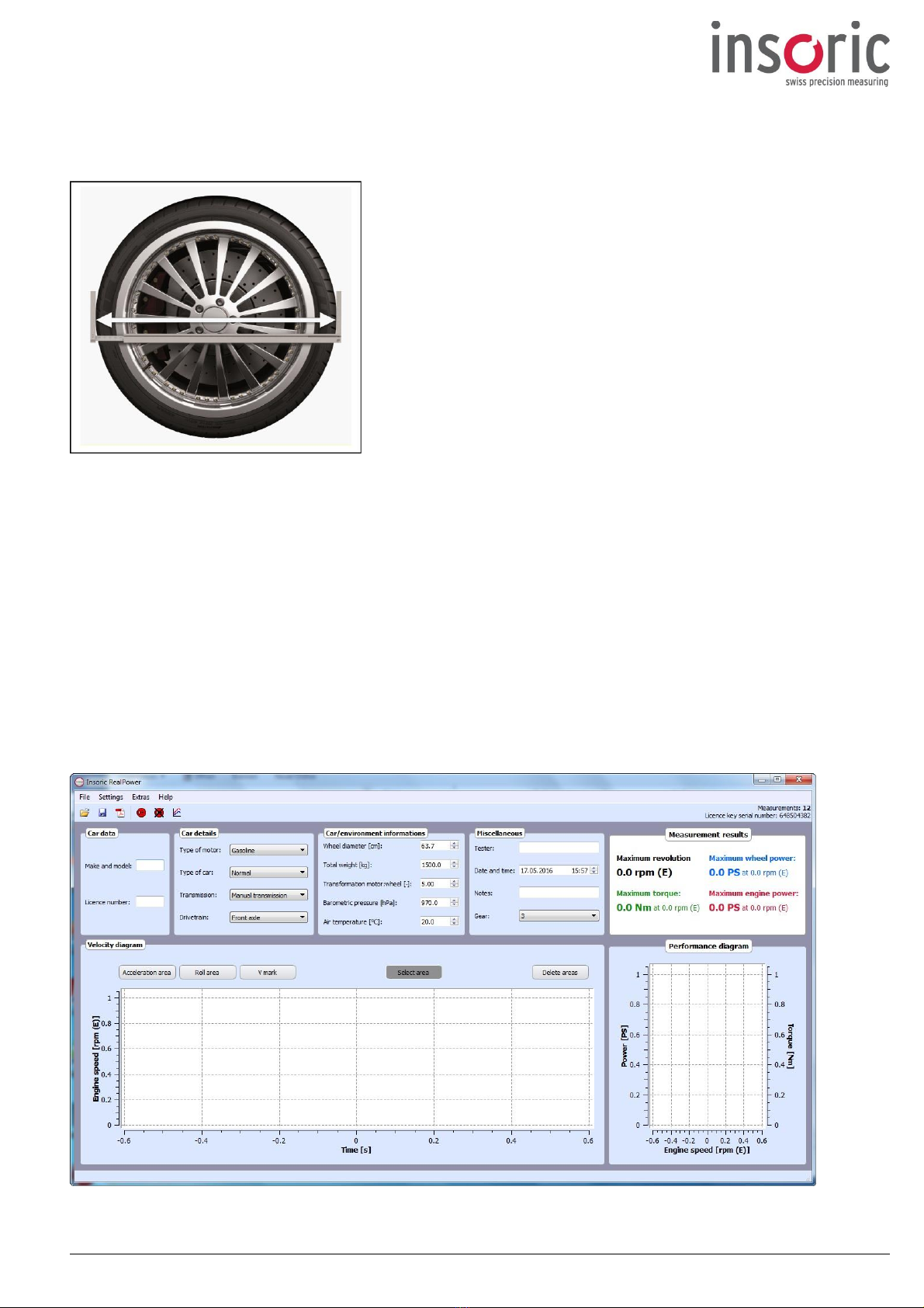
2.6.2 Measuring the wheel diameter
The wheel diameter is measured using the wheel measuring device*supplied with the product and
subsequently entered in the RealPower software program.
The wheel diameter should be measured horizontally, as in that
position there is always sufficient space between the wheel and the
wheel arch.
To obtain the precise measurement, the diameter must be
measured horizontally though the centre of the hub.
*
RealPower Dyno-System Professionell
2.7 Analysing the data
2.7.1 Starting the RealPower software
When the RealPower software is installed, a desktop shortcut is automatically created.
The shortcut is displayed as an icon.
To start the RealPower software you require the licence key (see Section 1.8). Plug the USB stick (see
Section 1.3, item 10) on which the licence key is stored into an available USB port on your PC.
Double-clicking the program icon will then start the user interface of the RealPower software.
Insoric RealPower / 10.06.2016 15 / 34
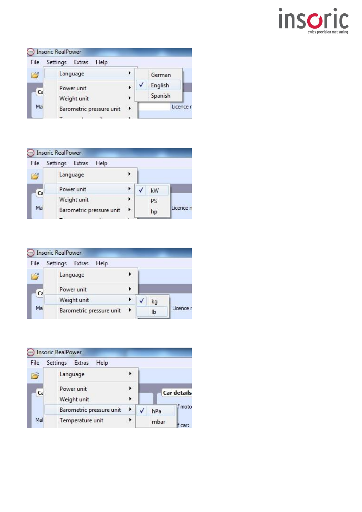
2.7.2 Entering basic settings
Go to the menu item "Settings Language" on
the pull-down menu and set the desired language.
The menu option "Settings" "Power unit"
allows you to choose between kW, PS and hp.
The menu option "Settings" "Weight unit"
allows you to choose between kg and lb.
The menu option "Settings" "Barometric
pressure unit" allows you to choose between hPa
and mbar.

Insoric RealPower / 10.06.2016 16 / 34
The menu option "Settings" "Temperature
unit" allows you to choose between ºC and ºF.
The menu option "Settings" "Torque unit"
allows you to choose between Nm and lbf ft.
The menu option "Settings" "Time unit"
allows you to choose between Samples, Seconds,
Minutes, Hours
Insoric RealPower / 10.06.2016 17 / 34
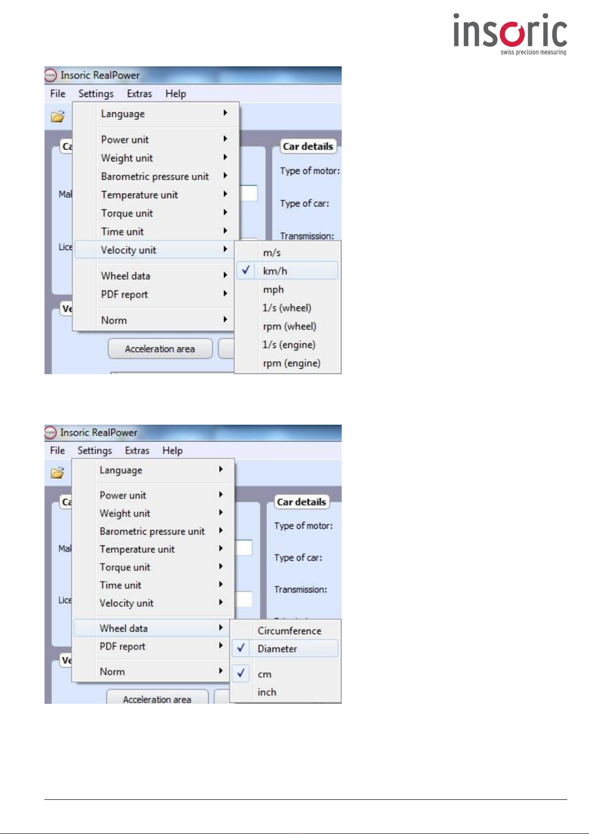
The menu option "Settings" "Velocity
unit" allows you to choose between m/s,
km/h, mph or
The option "Wheel data" allows you to
specify the unit for the wheel dimensions.
You should have measured the wheel
diameter using the wheel measuring device
* supplied with the product
(see Section 2.6.2).

Insoric RealPower / 10.06.2016 18 / 34
Using the option "PDF report" allows you
to show the wheel ratio in the PDF file.
Also can the power curve be shortend
towards the end zone
The setting "Norm" is for calculating the
adjustment and is preset.
ECC, DIN, ISO, SAE or none

Insoric RealPower / 10.06.2016 19 / 34
2.7.3 Reading the data from the RealPower module
Now connect the RealPower module to the PC using
the USB lead supplied and switch it on.
The green "ON" LED should start flashing.
Activate the RealPower module by clicking the "Read-
out module" button. The process of
reading/transferring the data then starts.
A green progress bar appears in the bottom right
corner of the application window.
Progress bar bottom right corner
Once all the data has been successfully read from the
RealPower module, the progress bar window is closed
and the power traces recorded appear on the velocity
diagram.
If there are problems with data transfer, an error
message appears.
After completion of data transfer, the RealPower software
automatically elevated by one the number of remaining
tests shown in the top right corner.

Insoric RealPower / 10.06.2016 20 / 34
Choosing "File Save" saves the data on your PC. The file name and where it is saved are always user-
definable.
The data remains on the RealPower module even after data transmission.
Clicking the "Delete module data" button completely
and irretrievably deletes all data from the RealPower
module memory.
Before wiping the module memory, please make sure that you have saved the data on your PC.
2.7.4 Analysing the results
2.7.4.1 Entering parameters
Now you should enter the parameters already mentioned in Section 2.6.1 in the RealPower software
program.
If you have completed the "Data check-list", you should have all the information to be entered
manually available at a glance.
Car data
In this window you enter the make, model and licence number of
the car. Those details will appear on the test certificate later on.
Make and model
Licence number
Car details
In this window, you select the type of motor, vehicle, transmission
and drive.
The options are selected from the drop-down lists.
Type of motor Car documents
Type of car Car documents
Transmission Car documents
Drivetrain Car documents
Table of contents


