SENTRONIC M-SYSTEM L4AS User manual
MODEL: L4AS
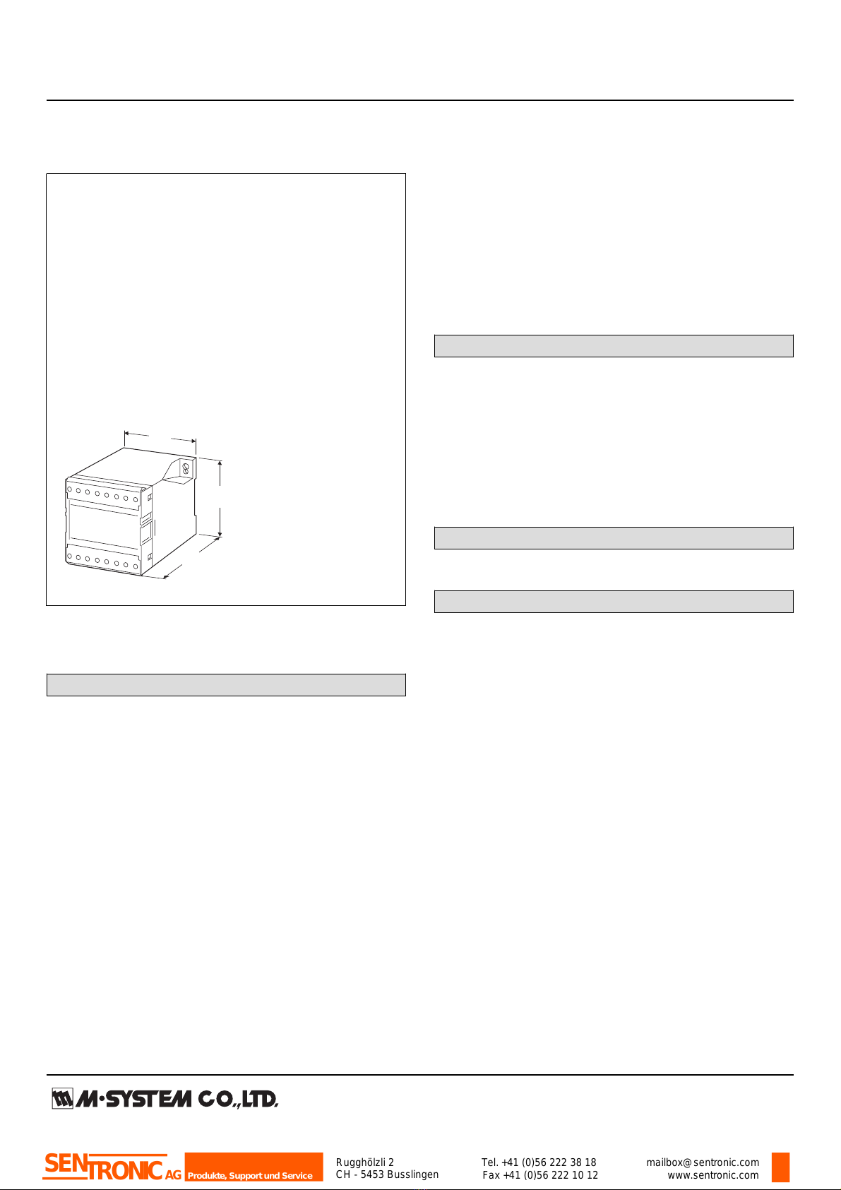
Plug-in Signal Conditioners M-UNIT
QUAD DC ALARM
Functions & Features
• Providing relay contact closures at preset DC input levels
• 4 setpoints: Hi/Hi, Hi, Lo, Lo/Lo
• Single turn screwdriver or dial setpoint adjustments
• Enclosed relays
• Relays can be powered 110 V DC
• Isolation up to 2000 V AC
• High-density mounting
Typical Applications
• Annunciator
• Various alarm applications
75
(2.95)
112
(4.41)
80
(3.15)
mm (inch)
MODEL: L4AS–[1][2][3]–[4]
ORDERING INFORMATION
•Code number: L4AS-[1][2][3]-[4]
Specify a code from below for each [1] through [4].
(e.g. L4AS-1A1-R)
[1] SETPOINT ADJUSTMENTS
1: Single-turn screws
2: Dials
[2] INPUT
Current
A: 4 – 20 mA DC (Input resistance 250 Ω)
Voltage
6: 1 – 5 V DC (Input resistance 1 MΩ min.)
[3] OUTPUT
1: 4 points; coil energized with input > setpoint
2: 2 points; coil energized with input < setpoint 2 points;
coil energized with input > setpoint
[4] POWER INPUT
AC Power
K: 85 – 132 V AC
(Operational voltage range 85 – 132 V, 47 – 66 Hz)
L: 170 – 264 V AC
(Operational voltage range 170 – 264 V AC, 47 – 66 Hz)
DC Power
R: 24 V DC
(Operational voltage range 24 V ±10 %, ripple 10 %p-p max.)
P: 110 V DC
(Operational voltage range 85 – 150 V, ripple 10 %p-p max.)
GENERAL SPECIFICATIONS
Construction: Stand-alone; terminal access at the front
Connection: M3.5 screw terminals
Housing material: Flame-resistant resin (black)
Isolation: Input to output to power
Setpoint adjustments: Single-turn screwdriver adjustments
or dials (front); -15 – +115 % independently
Hysteresis (deadband): Approx. 1 %
Front LEDs: Red lights turn on when the coils are energized.
INPUT SPECIFICATIONS
• DC Current: Input resistor incorporated
OUTPUT SPECIFICATIONS
•Relay Contact: 100 V AC @ 1 A (cos ø = 1)
120 V AC @ 1 A (cos ø = 1)
240 V AC @ 0.5 A (cos ø = 1)
30 V DC @ 1 A (resistive load)
Maximum switching voltage: 380 V AC or 125 V DC
Maximum switching power: 120 VA or 30 W
Minimum load: 5 V DC @ 10 mA
Mechanical life: 5 x 10⁷ cycles
For maximum relay life with inductive loads, external
protection is recommended.
Rugghölzli 2
CH - 5453 Busslingen Tel.+41 (0)56 222 38 18
Fax +41 (0)56 222 10 12 mailbox@sentronic.com
www.sentronic.com
Produkte, Support und Service
SENTRONICAG

MODEL: L4AS
Alarm Trip Operation Terminal No. in parentheses
0 50 100
Input
(%) No.1No.2No.3No.4
Output 1
(3–5)ON (3–4)ON
Output 2
(6–8)ON (6–7)ON
Output 3
(11–13)ON
Output 4
(11–12)ON
(14–15)ON
(14–16)ON
•Output Code : 2
Trip Operation in Power Failure:
Terminals 3 –5, 6 – 8, 11 – 13 and 14 – 16 turn ON.
0 50 100
Input
(%) No.1
(LL) No.2
(L) No.3
(H) No.4
(HH)
Output 1
(3–4)ON (3–5)ON
Output 2
(6–8)ON
(6–7)ON
Output 3
(11–13)ON
Output 4
(11–12)ON
(14–15)ON
(14–16)ON
•Output Code : 1
Trip Operation in Power Failure:
Terminals 3 –5, 6 – 8, 11 – 13 and 14 – 16 turn ON.
INSTALLATION
Power Consumption
•AC Power input: Approx. 4.5 VA
•DC Power input: Approx. 2 W (80 mA at 24 V)
Operating temperature: -5 to +55°C (23 to 131°F)
Operating humidity: 30 to 90 %RH (non-condensing)
Mounting: Surface or DIN rail
Weight: 350 g (0.77 lbs)
PERFORMANCE in percentage of span
Setpoint accuracy: ±0.3 %
Temp. coefficient: ±0.05 %/°C (±0.03 %/°F)
Response time: ≤ 0.5 sec. (0 – 100 % at 90 % setpoint)
Line voltage effect: ±0.1 % over voltage range
Insulation resistance: ≥ 100 MΩ with 500 V DC
Dielectric strength: 2000 V AC @1 minute (input to output
to power to ground)
Rugghölzli 2
CH - 5453 Busslingen Tel.+41 (0)56 222 38 18
Fax +41 (0)56 222 10 12 mailbox@sentronic.com
www.sentronic.com
Produkte, Support und Service
SENTRONICAG
MODEL: L4AS
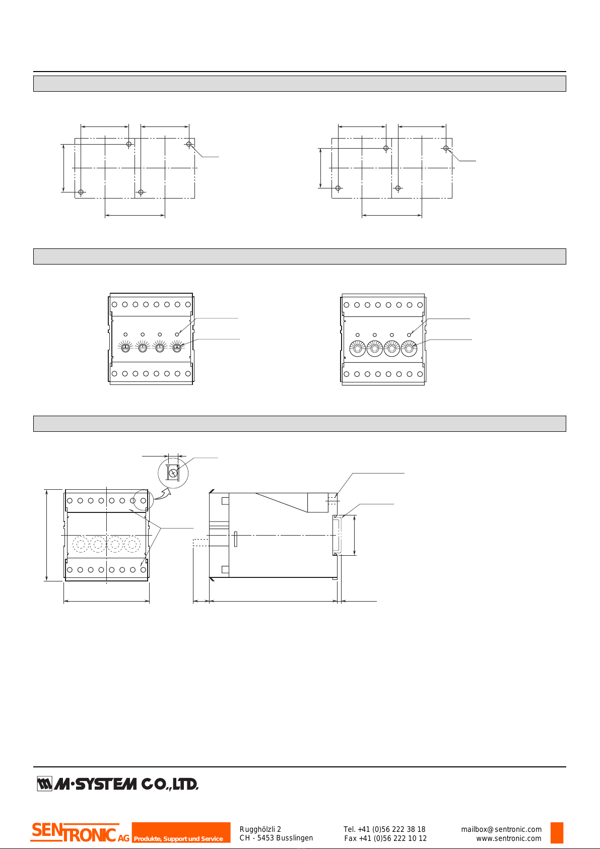
MOUNTING REQUIREMENTS
2–M5
60 (2.36)
75 (2.95) MIN.
60 (2.36)
60 (2.36)
عM5 SCREWS
2–M4
60 (2.36)
75 (2.95) MIN.
60 (2.36)
50 (1.97)
عM4 SCREWS
EXTERNAL VIEW
1 2 3 4
Monitor LED
Setpoint Adj.
1 2 3 4
Monitor LED
Setpoint Adj.
عSCREWDRIVER ADJUSTMENTS عDIAL ADJUSTMENTS
EXTERNAL DIMENSIONS & TERMINAL ASSIGNMENTS unit: mm (inch)
112 (4.41)
[3.3 (.13)]
35.4 (1.39)
DIN RAIL
35mm wide
14*
(.55)
8 (.31) 16–M3.5
SCREW
75 (2.95)
80 (3.15)
TERMINAL
COVER
2–5.8 (.23) dia. or
2–4.8 (.18) dia.
MTG HOLE
8 (.31) deep
9 10 11 12 13 14 15 16
123456 7 8
*Dial adj.
Rugghölzli 2
CH - 5453 Busslingen Tel.+41 (0)56 222 38 18
Fax +41 (0)56 222 10 12 mailbox@sentronic.com
www.sentronic.com
Produkte, Support und Service
SENTRONICAG

MODEL: L4AS
SCHEMATIC CIRCUITRY & CONNECTION DIAGRAM
U(+)
V(–)
POWER
9
10
Comparator
+
–
INPUT
1Low Drift
Amplifier
2
Ry
5
4
3
8
7
6
ALARM OUTPUT 1
*Input shunt resistor incorporated for current input.
*
LOAD
Inductive
Load (Coil)
Varistor or Spark
Quenching Circuit
•DC Powered
LOAD
Inductive
Load (Coil)
Diode, Varistor or
CR Circuit
Relay Protection
•AC Powered
Comparator
Ry
13
12
11
Comparator
Ry
16
15
14
Comparator
Ry
No.1 SET
No.2 SET
No.3 SET
No.4 SET
ALARM OUTPUT 2
ALARM OUTPUT 3
ALARM OUTPUT 4
ع
Specifications are subject to change without notice.
Rugghölzli 2
CH - 5453 Busslingen Tel.+41 (0)56 222 38 18
Fax +41 (0)56 222 10 12 mailbox@sentronic.com
www.sentronic.com
Produkte, Support und Service
SENTRONICAG
L4AS
P. 1 / 3 EM-1991 Rev.6
BEFORE USE ....
Thank you for choosing M-System. Before use, check the
package you received as below.
If you have any problems or questions with the product,
please contact M-System’s Sales Office or representatives.
■ PACKAGE INCLUDES:
Signal conditioner ................................................... (1)
■ MODEL NO.
Check that model No. described on specification label is
exactly what you ordered.
■ INSTRUCTION MANUAL
This manual describes necessary points of caution when you
use this product, installation, connection and basic mainte-
nance procedures.
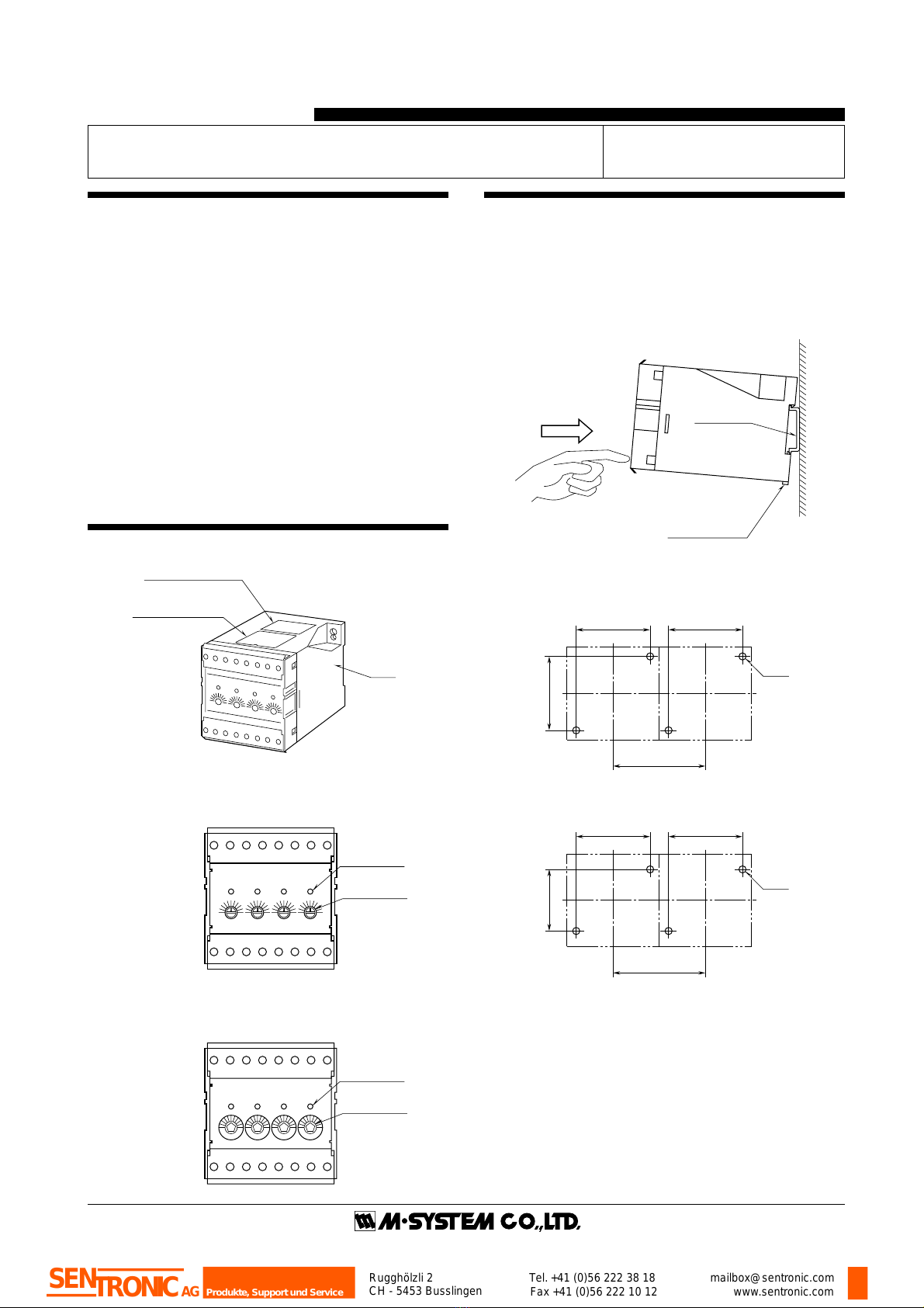
COMPONENT IDENTIFICATION
■ FRONT PANEL CONFIGURATION
INSTRUCTION MANUAL
MODEL L4AS
QUAD DC ALARM
INSTALLATION
■ DIN RAIL MOUNTING
Set the unit so that its DIN rail adaptor is at the bottom.
Position the upper hook at the rear side of the unit on the DIN
rail and push in the lower. When removing the unit, push
down the DIN rail adaptor utilizing a screwdriver (–) and
pull.
■ WALL MOUNTING mm (inch)
MODEL
L4AS
50
100
%
0
2
134
50
100
%
0
50
100
%
0
50
100
%
0
Specification Label
Connection Diagram
Body
1234
Monitor LED
Setpoint Adj.
1234
Monitor LED
Setpoint Adj.
■SCREWDRIVER ADJUSTMENTS
■DIAL ADJUSTMENTS
DIN Rail
35mm wide
Spring Loaded
DIN Rail Adaptor
2–M5
60 (2.36)
75 (2.95) MIN.
60 (2.36)
60 (2.36)
■M5 SCREWS
2–M4
60 (2.36)
75 (2.95) MIN.
60 (2.36)
50 (1.97)
■M4 SCREWS
Rugghölzli 2
CH - 5453 Busslingen Tel.+41 (0)56 222 38 18
Fax +41 (0)56 222 10 12 mailbox@sentronic.com
www.sentronic.com
Produkte, Support und Service
SENTRONICAG
L4AS
P. 2 / 3 EM-1991 Rev.6
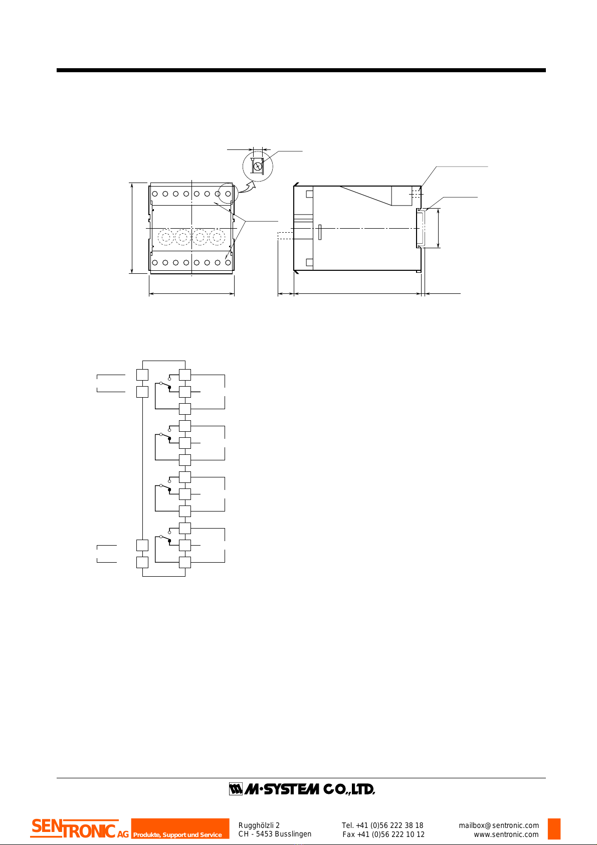
TERMINAL CONNECTIONS
Connect the unit as in the diagram below or refer to the connection diagram label on top of the unit.
■ EXTERNAL DIMENSIONS mm (inch)
■ CONNECTION DIAGRAM
112 (4.41) [3.3 (.13)]
35.4 (1.39)
DIN RAIL
35mm wide
14*
(.55)
8 (.31) 16–M3.5
SCREW
75 (2.95)
80 (3.15)
TERMINAL
COVER
2–5.8 (.23) dia. or
2–4.8 (.18) dia.
MTG HOLE
8 (.31) deep
910111213141516
12345678
*Dial adj.
U(+)
V(–)
9
10
+
–
INPUT
POWER
1
2 5
4
3
8
7
6
ALARM OUTPUT 1
13
12
11
16
15
14
ALARM OUTPUT 2
ALARM OUTPUT 3
ALARM OUTPUT 4
Rugghölzli 2
CH - 5453 Busslingen Tel.+41 (0)56 222 38 18
Fax +41 (0)56 222 10 12 mailbox@sentronic.com
www.sentronic.com
Produkte, Support und Service
SENTRONICAG

L4AS
P. 3 / 3 EM-1991 Rev.6
CHECKING
1) Terminal wiring: Check that all cables are correctly
connected according to the connection diagram.
2) Power input voltage: Check voltage across the terminal 9
–␣ 10 with a multimeter.
3) Input: Check that the input signal is within 0 – 100% of
the full-scale.
4) Relay operation: Confirm that each relay trips properly
according to the figure below.
5) Output load: Check that the output load is 380V AC/
100VA or 125V DC/30W at the maximum. For maximum
relaylifewithinductiveload,externalprotectionisrecom-
mended.
ALARM RELAY OPERATIONS
• Trip operation in power failure: terminals 3 – 5, 6 –␣ 8, 11 –
13, 14 – 16 turn ON.
POINTS OF CAUTION
■ GENERAL
• Before you remove the unit or mount it, turn off the power
supply and input signal for safety.
■ ENVIRONMENT
• When heavy dust or metal particles are present in the air,
install the unit inside proper housing and ventilate it.
• Do not install the unit where it is subjected to continuous
vibration. Do not apply physical impact to the unit.
• Environmental temperature must be within -5 to +55°C (23
to131°F)withrelativehumiditywithin30 to 90% RH in order
to ensure adequate life span and operation.
■ WIRING
• Do not install cables (power supply, input and output) close
to noise sources (relay drive cable, high frequency line, etc.).
• Do not bind these cables together with those in which noises
are present. Do not install them in the same duct.
■ AND ....
• The unit is designed to function as soon as power is
supplied, however, a warm up for 10 minutes is required for
satisfying complete performance described in the data sheet.
MAINTENANCE
Regular calibration procedure is explained below:
■ CALIBRATION
Warm up the unit for at least 10 minutes.
• Hi or HH Setpoint
Increasetheinputsignal from a value lower than the setpoint
and check that the trip point remains within the accuracy
described in the data sheet.
• Lo or LL Setpoint
Decrease the input signal from a value higher than the
setpoint and check that the trip point remains within the
accuracy described in the data sheet.
When the trip points are out of tolerance, contact M-System’s
Sales Office or local representatives.
0 50 100
Input
(%) No.1 No.2 No.3 No.4
Output 1
(3–5)ON (3–4)ON
Output 2
(6–8)ON (6–7)ON
Output 3
(11–13)ON
Output 4
(11–12)ON
(14–15)ON
(14–16)ON
•Output Code : 1
0 50 100
Input
(%) No.1
(LL) No.2
(L) No.3
(H) No.4
(HH)
Output 1
(3–4)ON (3–5)ON
Output 2
(6–8)ON
(6–7)ON
Output 3
(11–13)ON
Output 4
(11–12)ON
(14–15)ON
(14–16)ON
•Output Code : 2
Rugghölzli 2
CH - 5453 Busslingen Tel.+41 (0)56 222 38 18
Fax +41 (0)56 222 10 12 mailbox@sentronic.com
www.sentronic.com
Produkte, Support und Service
SENTRONICAG
Table of contents
Other SENTRONIC Test Equipment manuals


Popular Test Equipment manuals by other brands


Webasto
Webasto ABC-600 Installation, operation and maintenance manual

Cole Parmer
Cole Parmer 90225-00 operating instructions

Chauvin Arnoux
Chauvin Arnoux Multimetrix XDO2025 user manual

YOKOGAWA
YOKOGAWA 701921 user manual

M.C. MILLER
M.C. MILLER VADER user guide

Ametek
Ametek TAYLOR HOBSON Surtronic S-100 Series user guide