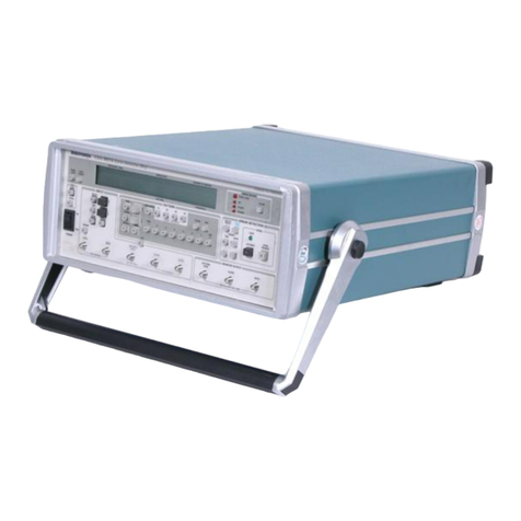
ATSI PCMT-8800 User manual

PCMT-8800
Conflict Monitor Tester
User's Manual
Revision 1.0

Table of Contents
1. Explanation of Symbols, Terms, and Abbreviations...........................................................................................................3
2. Safety Information............................................................................................................................................................. 4
3. Introd ction........................................................................................................................................................................ 5
4. PCMT-8800 Test Manager Software Installation................................................................................................................ 6
4.1. Comp ter Req irements........................................................................................................................................... 6
4.2. PCMT-8800 Interface Software Installation............................................................................................................... 6
4.3. PCMT-8800 USB Driver Installation.......................................................................................................................... 6
5. Preparing to Test............................................................................................................................................................... 7
5.1. Setting Up the PCMT................................................................................................................................................. 7
5.2. Preparing the Monitor to Test..................................................................................................................................... 7
5.3. Monitor Switch Settings............................................................................................................................................. 8
6. Using the Test Manager Software...................................................................................................................................... 9
6.1. Monitor Info................................................................................................................................................................ 9
6.2. Test Set p................................................................................................................................................................ 10
6.3. Settings.................................................................................................................................................................... 11
6.4. PCMT Info .............................................................................................................................................................. 12
6.5. Report Viewer.......................................................................................................................................................... 12
6.6. Help......................................................................................................................................................................... 12
6.7. Starting a Test.......................................................................................................................................................... 12
7. Test Descriptions............................................................................................................................................................. 14
7.1. NEMA TS1 Test Descriptions .................................................................................................................................. 14
7.1.1 System / Timing Tests ...................................................................................................................................... 14
7.1.2 Voltage Tests.................................................................................................................................................... 18
7.1.3 Optional Tests................................................................................................................................................... 19
7.2. NEMA TS2 Test Descriptions................................................................................................................................... 24
7.2.1 System / Timing Tests ...................................................................................................................................... 24
7.2.2 Voltage Tests.................................................................................................................................................... 29
7.2.3 Optional Tests................................................................................................................................................... 32
7.2.4 Optional Tests (MMU2 FYA)............................................................................................................................. 37
7.3. System 170 Type 210 Test Descriptions................................................................................................................. 42
7.3.1 System / Timing Tests....................................................................................................................................... 42
7.3.2 Voltage Tests.................................................................................................................................................... 47
7.3.3 Optional Tests................................................................................................................................................... 48
7.4. System 270 Type 2010 / LADOT 2018 Test Descriptions........................................................................................53
7.4.1 System / Timing Tests....................................................................................................................................... 53
7.4.2 Voltage Tests.................................................................................................................................................... 59
7.4.3 Optional Tests................................................................................................................................................... 61
7.5 Canadian Fast Flash Test Descriptions.................................................................................................................... 66
8. Tro bleshooting............................................................................................................................................................... 68
9. Electrical and Mechanical Specifications......................................................................................................................... 69
10. Service and Calibration.................................................................................................................................................. 70
11. Limited Warranty and Liability........................................................................................................................................ 71
12. Packing Yo r PCMT for Shipment................................................................................................................................. 72
13. Ret rn Merchandise Form............................................................................................................................................. 73
Appendix A. Connecting m ltiple testers to one comp ter................................................................................................... 74
Appendix B. Flashing Yellow Arrow (FYA) Mapping............................................................................................................. 76
PCMT-8800 User's Man al Rev. 1.0 1 of 80

PCMT-8800 User's Man al Rev. 1.0 2 of 80

1. Explanation of Symbols, Terms, and Abbreviations
1. Explanation of Symbols Terms and Abbreviations
Graphical Symbols
The following symbols are sed on the PCMT-8800 enclos re and in this man al. Anytime one of these symbols is
enco ntered the ser sho ld be aware of the condition described here next to each symbol.
Ca tion. Risk of danger. Read the Users Man al before operating the PCMT-8800
Ca tion. Risk of electric shock.
Terms and Abbreviations
The following is a list of terms and abbreviations sed thro gho t the text of this man al along with the definition.
Term or Abbreviation Definition
Caltrans Refers to monitors that conform to State of California Department of Transportation:
Transportation Electrical Eq ipment Specifications (TEES) – 2009, Chapter 3, Section 6
Model 210 Monitor Unit
Conflict Monitor See MMU
mA milliamperes (tho sandths of an amp)
Monitor See MMU
MMU Malf nction Management Unit: Device sed to detect and respond to improper, conflicting
signals and improper operating voltages in a traffic control system.
ms milliseconds (tho sandths of a second)
NEMA National Electrical Man fact rers Association
PC Personal comp ter
SDLC Synchrono s Data Link Control. The digital comm nications link between the controller and
conflict monitor in a TS2 type traffic signal control cabinet.
Tester The ATSI PCMT-8800 Conflict Monitor Tester
TS1 Refers to monitors that conform to NEMA Traffic Control Systems Standards TS1-1989
TS2 Refers to monitors that conform to NEMA Standards P blication TS 2-2003 v02.06
USB Universal Serial B s. This is a standard connection for connecting comp ters and
peripheral devices that m st comm nicate with each other. USB ports are commonly
available on most modern comp ters. This is the type of connection that is sed for
comm nication between the PCMT-8800 and a comp ter.
VDC Volts DC
Vrms Volts RMS (root-mean-sq ared)
PCMT-8800 User's Man al Rev. 1.0 3 of 80

2. Safety Information
2. Safety Information
IMPORTANT SAFETY INFORMATION !
READ THE OPERATING INSTRUCTIONS BEFORE ATTEMPTING TO USE THE PCMT-8800 !
IMPORTANT SAFETY INFORMATION !
The PCMT-8800 (Tester) sho ld only be sed by q alified and a thorized traffic signal technicians or engineers who are
familiar with generally accepted electrical safety practices as well as local and national safety codes. To avoid possible
electric shock, b rns, or fire, read all information contained in this man al before attempting to se the Tester.
•Do not se the Tester aro nd explosive gas, vapor, or d st.
•Do not se the Tester in a wet environment.
•Do not attempt to open any part of the Tester enclos re.
•Only se the power cord provided with the Tester.
•The Tester sho ld only be powered from 120V AC / 60Hz.
•Only se the monitor testing cables that were s pplied by ATSI.
•Before each se, inspect the monitor testing cables for damage, s ch as broken connector hoods, or damaged wire
ins lation.
•D ring monitor testing, the testing cables carry 120V AC power. Using damaged cables, or cables not s pplied by
ATSI, co ld res lt in damage to the tester or monitor, and potentially lethal electric shock.
•The PCMT-8800 has no ser serviceable parts. Under no circ mstances sho ld the ser attempt to open the
enclos re. If the tester appears to be malf nctioning, contact ATSI to make arrangements for repair.
Testing Known Bad Monitors
Monitors which have been s bjected to lightning strikes or other severe electrical stress co ld ca se damage to the
PCMT. If yo s spect a monitor has been s bjected to a lightning strike or similar electrical stress, it is recommended that
yo first check the monitor o t in the shop, in a sim lated signal environment, or on a man al tester. In this test set p,
internal monitor shorts will merely blow f ses - on the PCMT it co ld res lt in internal tester damage which will req ire
ret rning the tester to ATSI for repairs.
Non-NEMA Monitors
If yo are performing NEMA tests, be certain that the monitor is NEMA-compatible. Some non-NEMA monitors se a
NEMA-type connector, with non-NEMA wiring. This co ld ca se damage to the tester or to the monitor itself when power
is applied. If yo are not s re if yo r monitor is NEMA compatible, contact the monitor man fact rer.
PCMT-8800 User's Man al Rev. 1.0 4 of 80

3. Introd ction
3. Introduction
The PCMT-8800 performs comprehensive testing of vario s types of conflict monitors to ens re that they are f nctioning
in accordance with the req irements of the applicable p blished standard. The following monitor types may be tested:
NEMA TS1 3, 6, 12 18 Channel
NEMA TS2 (MMUs) 12 or 16 Channel Mode
NEMA TS2 MMU 8 Channel (Canada)
System 170 Type 210 16 or 18 Channel
System 2070 Type 2010 16 Channel
LADOT Model 2018
Operating the PCMT-8800 req ires the Test Manager Software to be installed on a comp ter r nning Microsoft Windows
XP or later. The comp ter controls the testing seq ence by sending commands to the PCMT over a USB connection. The
PCMT provides inp t signals to the conflict monitor and verifies that it responds correctly to sim lated conditions that may
occ r in a traffic signal control cabinet.
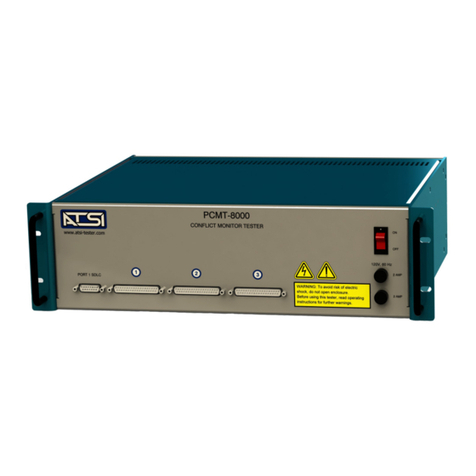
PCMT-8800 Tester shown with TS2 Cables.
C stom cables are req ired for each monitor type that is tested.
The PCMT may be sed as a bench-top nit, or it may be mo nted in a standard 19" rackmo nt enclos re. For m lti- nit
systems, one comp ter can control m ltiple PCMTs to enable sim ltaneo s testing of many monitors. An optional
carrying case is also available for those sers who m st perform field testing of monitors.
PCMT-8800 User's Man al Rev. 1.0 5 of 80

4. PCMT-8800 Test Manager Software Installation
4. PCMT-8800 Test Manager Software Installation
4.1. Computer Requirements
Windows 10 (minim m)
At least one available USB port.
A PDF reader m st be installed. Adobe Acrobat Reader can be downloaded for free at www.adobe.com. Most of the
other freely available PDF readers sho ld also work.
4.2. PCMT-8800 Interface Software Installation
Installation of the software may req ire administrative access to the comp ter.
To install the software that was downloaded from o r website , do ble-click the downloaded exec table file to r n the
installation. Follow the instr ctions in the software installation wizard.
Note: Do not forget to install the ATSI Tester USB device driver for PCMT-8800.
4. . PCMT-8800 USB Driver Installation
To comm nicate with the PCMT-8800 an ATSI Tester USB driver needs to be installed. The latest version of the driver
can be downloaded from o r website: www.atsi-tester.com.
PCMT-8800 User's Man al Rev. 1.0 6 of 80

5. Preparing to Test
5. Preparing to Test
5.1. Setting Up the PCMT
To set p the PCMT for testing :
1. P t the On / Off switch located on the front of the PCMT in the Off position.
2. Connect the USB B-Type end of the USB cable to the port on the back of the PCMT.
3. Connect the USB A-Type end of the USB cable to yo r comp ter USB port.
4. Connect the monitor cable connectors to the correspondingly labeled female connectors on the front of the PCMT.
5. DO NOT t rn the On / Off switch to the On position ntil the monitor connectors are connected to the monitor (See
Preparing the Monitor to Test).
5.2. Preparing the Monitor to Test
On both NEMA TS1 and NEMA TS2 monitors, ens re that the program card is blank when r nning a basic Certification
test. Refer to Monitor Switch Settings for additional help with the conflict monitor's extended feat re switches.
System 170 Model 210 monitors sho ld not have any diodes c t (permissives) or Yellow inhibits on the programming card
for Certification Testing. If yo r agency inhibits the Yellow monitoring f nction for walk signals or for all channels, yo
sho ld still test the monitor with a "clean" programming card for Certification Testing. This will res lt in a record that all
monitor f nctions described in the standard were working on all channels at the time of the test.
For all monitor types, if yo choose to r n the optional Permissive Tests to verify a programmed intersection card, yo will
be prompted by the software to change the card at the beginning of the tests.
Once yo have verified that the monitor settings are correct, pl g the monitor cable circ lar MS style connectors into the
corresponding connector on the monitor (NEMA monitors) or insert the monitor into the monitor cable edge card connector
(210, 2010 monitors). Finally, verify that the PCMT has been set p as described in Setting Up the PCMT and then yo
may t rn the On / Off switch located on the front of the PCMT to the On position. At this point, yo sho ld hear fo r beeps
from the PCMT.
Note : If yo do not hear fo r beeps when the PCMT power is t rned on, there may be a problem with the nit. Refer to
Troubleshooting of this man al.
PCMT-8800 User's Man al Rev. 1.0 7 of 80

5. Preparing to Test
5. . Monitor Switch Settings
ATSI recommends sing the following g idelines for testing yo r conflict monitors. Please refer to yo r monitor's man al
for instr ctions on how to change the settings on yo r partic lar monitor. The settings in this section are j st g idelines.
The switches may be labeled differently from man fact rer to man fact rer. Not all monitors are capable of r nning all of
the optional tests. Please refer to yo r monitor's man al to find o t if yo r monitors are capable of r nning the optional
tests.
210 Standard
Watch Dog Enable = ON
All SSM or Field Check Enables = ON
BND Disable = ON
GY Enable = ON
2010 Standard
Watch Dog Enable = ON
RF 2010 = ON
GY Enable = ON
All SSM or Field Check Enables = ON
TS1 Standard
Minim m Flash between 4 and 11 seconds
GY Enable = ON
BND Disable = ON
D al Enable = ON
SSM or Channel Enables = ON
TS2 Standard
GY Enable = ON
RP Disable = ON
Field Check / D al Enable = ON
TS1 Canadian Standard
Minim m Flash between 4 and 11 seconds
GY Enable = ON
BND Disable = ON
D al Enable = ON
SSM or Channel Enables = ON
Fast Flash Enable = ON
TS2 Canadian Standard
GY Enable = ON
RP Disable = ON
Field Check / D al Enable = ON
Fast Flash Enable = ON
TS2 12/16 Channel MMU2 FYA
Config re the MMU2 for the mode being tested
Use programming card programmed for mode being tested
Enable all channel pairs
Enable flash rate detection
Disable R and Y inp ts on sparse channel
PCMT-8800 User's Man al Rev. 1.0 8 of 80

6. Using the Test Manager Software
6. Using the Test Manager Software
The Test Manager window is what yo will see when yo start the software. At the top of the window is the main men .
The f nction of each men item is described on the following pages. At the bottom of the window is the Start Test b tton.
Clicking this b tton will start a test based on the parameters that have been entered for Monitor Info and Test Setup.
6.1. Monitor Info
The Monitor Info window allows yo to enter information for the monitor to be tested. A
serial n mber or device ID is req ired to perform a certification test. All other info fields are
optional.
Manufacturer
Enter the name of the monitor man fact rer.
Model
Enter the model n mber of the monitor to be tested.
Serial Number
Enter the Serial n mber of the monitor to be tested. A serial n mber or device ID is
req ired to perform a certification test.
Device ID
This co ld be any reference n mber s ch as a cabinet n mber or yo r city or DOT's
inventory tag n mber. A serial n mber or device ID is req ired to perform a certification
test.
Location
Enter the intersection name, cabinet n mber, or location where this monitor is sed.
Tested By
Enter the name of the person who is doing the testing.
Agency
Enter in the name of yo r agency.
Notes
Enter any related notes that yo want to appear on the test report. If yo click the "Use Previo s" b tton, the text that was
last entered will be inserted in the Notes field. This is helpf l if yo are performing ann al certification tests on a n mber of
monitors, and yo want the notes to be the same for several tests in a row.
PCMT-8800 User's Man al Rev. 1.0 9 of 80

6. Using the Test Manager Software
6.2. Test Setup
Click on the Test Set p men item to open the Test Set p window. There are two types of tests that may be ran :
Certification or Diagnostic.
Test Standard
Click on the drop-down arrow to select the proper conflict monitor standard for the monitor yo wish to test. This
selection will determine what tests will be available for yo to choose from.
Monitor Type
Choose the type of monitor that yo are testing. This selection is based on the n mber of channels that the monitor has.
Test Type
Select “Certification” to r n the complete list of tests for the selected standard or “Diagnostic” to select individ al tests.
Test Laps
Select “One” to r n one complete test (“lap”) or “M ltiple” to r n thro gh a complete test a specified n mber of times.
Run Optional Tests
If the “R n Optional Tests” check box is checked. A list of optional tests will appear at the bottom of the window. Yo may
choose to r n any or all of these tests by selecting the check box next to the test name.
Optional Test Group
The Optional Test Gro p drop down box allows yo to select the optional tests that yo want to r n by clicking on the
appropriate entry. Once yo select a gro p of tests yo may give the gro p a niq e name by typing it in the Gro p Name
field, or yo may se the defa lt name.
PCMT-8800 User's Man al Rev. 1.0 10 of 80

6. Using the Test Manager Software
6. . Settings
Click on the Settings men item to select vario s test options.
Report Date Format
Choose the date format that will be sed on the test reports.
Report Time Format
Choose the time format that will be sed on the test reports.
Saved Report Format
If the “Verbose” option is chosen, the saved test report will show detailed descriptions of each
test that is ran. This option has the advantage of showing more information abo t each
test, however, the saved report will be many pages.
If the “Terse” option is chosen, the saved test report will only show the test name and a pass or
fail res lt. This option has the advantage of prod cing a report that can typically fit on one, or at most two pages, however
no detailed information abo t the tests is shown.
If the “Verbose and Terse” option is chosen, both types of reports will be saved.
Note: While the test is r nning, the report window will always show the verbose report.
Saved Report Font
Choose the font size that will be sed for the saved report. (Note: this does not affect the font size sed in the software
window.)
Saved Report Directory
This is the directory where the reports will be saved. Click the “Use Defa lt” b tton to se the PCMT-8800 defa lt
directory, or click browse to select a different directory.
Beep when response is required
If this check box is checked, the tester will beep anytime a ser response is req ired d ring a test.
PCMT-8800 User's Man al Rev. 1.0 11 of 80

6. Using the Test Manager Software
6.4. PCMT Info
Click on the PCMT Info men item to open the PCMT Info window. If the PCMT is
connected to the comp ter with the USB cable, clicking on the Get PCMT Info b tton will
connect to the PCMT and report the Serial N mber, Firmware Version, and Last
Calibration date.
If the software is not able to make a connection to the PCMT, it will be reported in the
information window. This may be an indication that the USB drivers are not installed.
Refer the the PCMT- 00 Test Manager Software Installation section of the man al for
USB driver installation instr ctions.
6.5. Report Viewer
Click on the Report Viewer men item to view any of the saved test reports. Note: A PDF reader m st be installed to view
the test reports (see Computer Requirements).
6.6. Help
Click on the Help men item to access instr ction man als, ret rn shipment forms, firmware pdates, and the ATSI web
sites.
6.7. Starting a Test
If yo have prepared yo r monitor to test by connecting the applicable cables (see Preparing To Test) and have entered
the correct information in the Monitor Info and Test Set p men items, yo are now ready to start a test. To start a test,
click the green start b tton in the bottom left corner of the software main window.
Power will now be applied to the monitor and yo will have a chance to change any switch settings or download any log
files from the monitor if necessary (see Monitor Switch Settings). When yo are ready for the test to contin e, click the
OK b tton and the testing will begin.
If yo need to cancel the test at anytime while it is r nning, click the read Cancel b tton in the lower right corner of the
testing window.
PCMT-8800 User's Man al Rev. 1.0 12 of 80

6. Using the Test Manager Software
When the test is complete, yo will have the option to save the report. Please note that if you do not save the report, the
test information will be lost.
PCMT-8800 User's Man al Rev. 1.0 13 of 80

7. Test Descriptions
7. Test Desc riptions
All of the PCMT-8800 tests described below are based on the p blished standard that is listed. It is the intent of ATSI to
test all of the req irements of the listed standard as thoro ghly as possible. The tests are based on o r best interpretation
of the standards and are s bject to the limitations of what is practical and feasible in a sim lated testing environment.
Each individ al j risdiction (i.e. state, co nty, city) may have specific req irements or practices that are ro tinely followed
which deviate from the applicable standard or ignore certain parts. F rthermore, some monitor man fact rers may have
certain feat res enabled or disabled in their devices to accommodate s ch deviations from the applicable standard.
Therefore, the ser has the option of disabling certain tests. These tests are listed as “optional” in the Test Set p window.
There may also be certain tests that are related to monitor f nctions that deviate from the applicable standard. These
deviations my be d e to special feat res that have been added and are not yet covered in the standard. There may also
be cases where monitors are old and have been man fact red according to the req irements of a previo s version of the
applicable standard. In s ch cases, special tests may be provided to accommodate these deviations from the c rrent
version of the standard. It is the responsibility of the user to determine what tests are appropriate for their local
requirements.
7.1. NEMA TS1 Test Descriptions
These tests are based on the req irements of NEMA Standard TS-1-1994.
7.1.1 System / Timing Tests
Interlock Sensing
Test Description :
Verify that the Interlock inp t is working.
Test Sequence :
1. Interlock inp t set at 24V.
2. Check Interlock o tp t.
3. Interlock inp t set at 0V.
4. Check Interlock o tp t.
Monitor Response to PASS :
State of Interlock o tp t identical to Interlock inp t.
Power Failure Ignore
Test Description :
Verify the monitor ignores an AC power interr pt lasting less than 450ms.
Test Sequence :
1. Monitor is powered p in the q iescent state.
2. Monitor AC power is t rned off for less than 450ms and then back on.
3. Fa lt state is checked.
Monitor Response to PASS :
Loss of AC power for less than 450ms m st NOT ca se fa lt.
Power Failure Detect
Test Description :
Verify the monitor recognizes an AC power interr pt lasting more than 500ms.
Test Sequence :
1. Monitor is powered p in the q iescent state.
PCMT-8800 User's Man al Rev. 1.0 14 of 80

7. Test Descriptions
2. Monitor AC power is t rned off.
3. Delay
4. Monitor AC power is t rned on.
5. Fa lt state is checked.
6. Increment delay time and repeat 2 and 5 ntil monitor is fo nd in the fa lt state.
Monitor Response to PASS :
Loss of AC power for greater than 500ms m st ca se fa lt.
Initial Flash
Test Description :
Verify that the initial flash time setting of the monitor is within the limits.
Test Sequence :
1. Monitor is powered p in the q iescent state.
2. AC power is removed for 5 seconds.
3. AC power is reapplied.
4. The monitor Initial Flash (fa lt state) time is meas red.
Monitor Response to PASS :
Initial Flash time is ro nded to the nearest second and m st be greater than or eq al to 4 seconds and less than or
eq al to 11 seconds.
Start Delay
Test Description :
Verify that the Start Delay o tp t is active when power is initially applied to the monitor.
Test Sequence :
1. Monitor is powered p in the q iescent state.
2. AC power is removed for 5 seconds.
3. AC power is reapplied.
4. The active time of the Start Delay o tp t is meas red.
Monitor Response to PASS :
Start Delay o tp t active for greater than or eq al to 1.5 seconds and less than or eq al to 3.5 seconds.
DC1 (or DC2) Failure Ignore
Test Description :
Verify that the monitor ignores a loss of DC power lasting less than 125ms.
Test Sequence :
1. Monitor is powered p in the q iescent state.
2. DC power (24V) is t rned off for less than 125ms.
3. Delay 250ms.
4. Fa lt state is checked.
Monitor Response to PASS :
Loss of DC power for less than 125ms m st NOT ca se the monitor to go into the fa lt state.
DC1 (or DC2) Failure Detect
Test Description :
Verify that the monitor recognizes a loss of DC power lasting more than 175ms.
Test Sequence :
1. Monitor is powered p in the q iescent state.
PCMT-8800 User's Man al Rev. 1.0 15 of 80

7. Test Descriptions
2. DC power (24V) is t rned off for less than 125ms.
3. Delay 250ms.
4. Fa lt state is checked.
5. If monitor in fa lt state, test is over.
6. Increase the DC1 off time.
7. Repeat 3 thro gh 6.
Monitor Response to PASS :
Loss of DC power for more than 175ms m st ca se the monitor to go into the fa lt state.
DC Monitor Inhibit
Test Description :
Verify that the monitor ignores a loss of DC1 and DC2 when the DC monitor inhibit inp t is active.
Test Sequence :
1. Monitor is powered p in the q iescent state.
2. DC Monitor Inhibit inp t is activated.
3. DC1 and DC2 are t rned off.
Monitor Response to PASS :
Monitor not fo nd in fa lt state when DC1 and DC2 are t rned off.
CVM Failure Ignore
Test Description :
Verify that the monitor ignores a loss of the CVM inp t lasting less than 125ms.
Test Sequence :
1. Monitor is powered p in the q iescent state.
2. CVM is t rned off for less than 125ms.
3. Delay 250ms.
4. Fa lt state is checked.
Monitor Response to PASS :
Loss of CVM for less than 125ms m st NOT ca se the monitor to go into the fa lt state.
CVM Failure Detect
Test Description :
Verify that the monitor recognizes a loss of the CVM inp t lasting more than 175ms.
Test Sequence :
1. Monitor is powered p in the q iescent state.
2. CVM is t rned off for less than 125ms.
3. Delay 250ms.
4. Fa lt state is checked.
5. If monitor in fa lt state, test is over.
6. Increase the CVM off time.
7. Repeat 3 thro gh 6.
Monitor Response to PASS :
Loss of CVM for more than 175ms m st ca se the monitor to go into the fa lt state.
Conflict Ignore Timing
Test Description :
Verify that the monitor ignores a conflict lasting less than 200ms..
PCMT-8800 User's Man al Rev. 1.0 16 of 80

7. Test Descriptions
Test Sequence :
1. Monitor is powered p in q iescent state.
2. Conflict is created on GRN1 and GRN 2.
3. Delay for less than 200ms.
4. Conflict is removed.
5. After 250ms delay, check for fa lt state.
Monitor Response to PASS :
For conflict lasting less than 200ms, monitor not fo nd in fa lt state.
Conflict Detect Timing
Test Description :
Verify that the monitor recognizes a conflict lasting more than 450ms.
Test Sequence :
1. Monitor is powered p in q iescent state.
2. Conflict is created on GRN1 and GRN 2.
3. Delay.
4. Conflict is removed.
5. After 250ms delay, check for fa lt state.
6. Increase Delay and repeat 3,4 and 5 ntil monitor is fo nd in fa lt.
7. Record Delay time.
Monitor Response to PASS :
For conflict lasting greater 450ms, monitor m st be in fa lt state.
Conflict Latching
Test Description :
Verify the detection of a conflict is latched thro gh an AC power loss.
Test Sequence :
1. Monitor is powered p in the q iescent state.
2. A conflict is created with GRN1 and GRN2.
3. AC power is removed.
4. Conflict condition is removed.
5. Delay 5 seconds.
6. AC power is reapplied.
Monitor Response to PASS :
Monitor m st still be in fa lt state when AC power is reapplied.
Redfail Ignore Timing
Test Description :
Verify that Redfail lasting less than 700ms is ignored.
Test Sequence :
1. Monitor is powered p in q iescent state.
2. All RED channels are at AC line voltage.
3. RED1 is t rned off for less than 700ms.
4. Check for fa lt state.
Monitor Response to PASS :
RED1 off for less than 700ms m st not ca se fa lt.
PCMT-8800 User's Man al Rev. 1.0 17 of 80

7. Test Descriptions
Redfail Detect Timing
Test Description :
Verify that Redfail lasting less than 700ms is ignored Redfail lasting more than 1000ms ca ses fa lt
Test Sequence :
1. Monitor is powered p in q iescent state.
2. All RED channels are at AC line voltage.
3. RED1 is t rned off for less than 700ms.
4. Check for fa lt state.
5. RED1 is t rned off for incrementally longer periods ntil fa lt state is fo nd.
6. RED1 off time is recorded.
Monitor Response to PASS :
RED1 off for greater than 1000ms m st ca se fa lt.
Redfail Latching
Test Description :
Verify that a Redfail condition is latched thro gh an AC power fail re.
Test Sequence :
1. Monitor is powered p in the q iescent state.
2. All RED channels are at AC line voltage.
3. A Redfail fa lt is created with RED1.
4. AC power is removed for 5 seconds.
5. RED1 is t rned back on.
6. AC power is reapplied.
Monitor Response to PASS :
Monitor m st go to fa lt state on Redfail fa lt. Monitor m st still be fo nd in fa lt state after AC power is removed,
RED1 t rned back on, and AC power is reapplied. (Redfail fa lt m st be latched thro gh power fail re.)
7.1.2 Voltage Tests
RED 70Vrms Sine Wave
Test Description :
Verify that a sine wave greater than 70Vrms is recognized as being "on" for every RED channel inp t.
Test Sequence :
1. Monitor is powered p in the q iescent state.
2. Redenable inp t is activated.
3. A sine wave greater than 70Vrms is applied to each RED channel.
Monitor Response to PASS :
Monitor m st NOT be fo nd in fa lt state.
RED 50Vrms Sine Wave
Test Description :
Verify that a sign wave less than 50Vrms is recognized as being "off" for every RED channel inp t.
Test Sequence :
1. Monitor is powered p in the q iescent state.
2. All RED channels are at AC line voltage.
3. Redenable inp t is activated.
4. A sine wave less than 50Vrms is applied to each RED channel one at a time.
PCMT-8800 User's Man al Rev. 1.0 18 of 80

7. Test Descriptions
5. fa lt state is checked for each channel.
Monitor Response to PASS :
50Vrms on any RED channel m st ca se monitor to go into fa lt state (Redfail fa lt).
GRN YEL WLK 25Vrms Recognition (Sine Wave Positive Rectified Negative Rectified)
Test Description :
Verify that the monitor recognizes a signal greater than 25Vrms as being "on" for every GYW channel.
Test Sequence :
1. Monitor is powered p in the q iescent state.
2. A signal greater than 25Vrms is applied to each GYW channel, one at a time, while GRN1 or GRN2 is at AC line.
3. fa lt state is checked for each channel.
Monitor Response to PASS :
Monitor m st go to fa lt state when a signal greater than 25Vrms is applied to any GYW channel.
(Note: This test is ran for f ll sine wave, positive rectified, and negative rectified signals.)
GRN YEL WLK 15Vrms (Sine Wave Positive Rectified Negative Rectified)
Test Description :
Verify that the monitor recognizes a signal less than 15Vrms as being "off" for every GYW channel.
Test Sequence :
1. Monitor is powered p in the q iescent state.
2. A signal less than 15Vrms is applied to each GYW channel, one at a time, while GRN1 or GRN2 is at AC line.
3. fa lt state is checked for each channel.
Monitor Response to PASS :
Monitor m st NOT go to fa lt state when a signal less than 15Vrms is applied to any GYW channel.
(Note: This test is ran for f ll sine wave, positive rectified, and negative rectified signals.)
GRN YEL WLK 1500pF
Test Description :
Verify that the monitor recognizes AC line voltage thro gh a 1500pF capacitor as being "off" for every GYW channel.
Test Sequence :
1. Monitor is powered p in the q iescent state.
2. AC line voltage thro gh a 1500pF capacitor is applied to each GYW channel one at a time while GRN1 or GRN2 is
at AC line voltage.
3. fa lt state is checked for each channel.
Monitor Response to PASS :
Monitor m st NOT go to fa lt state when AC line voltage thro gh a 1500pF capacitor is applied to any channel.
7.1.3 Optional Tests
GRN/GRN GRN/YEL GRN/WLK YEL/GRN YEL/YEL YEL/WLK WLK/GRN WLK/YEL WLK/WLK Permissive (Non-
Programmed Card)
Test Description :
R n this test with a "clean" (non-programmed) card to verify that there are no hidden permissives.
Test Sequence :
1. Monitor is powered p in the q iescent state.
2. Conflicting GRN, YEL, or WLK signals are presented to each channel pair.
PCMT-8800 User's Man al Rev. 1.0 19 of 80
Table of contents
Other ATSI Test Equipment manuals
