Inspire Ignire Wired User manual

Ignite - Wired (Heating & Hot Water) rev 2.0
www.inspirehomeautomation.co.uk

WHAT'S IN THE BO
1 x Assembled Room Thermostat consisting of
1 x Room Thermostat
1 x Wall Mount
1 x Wall Blanking Plate
1 x Screw Pack
INTRODUCTION
The Ignite Wired (Heating and Hot Water) Thermostat is designed to control a typical domestic
central heating system.
The Thermostat can switch two channels, Central Heating and Hot Water. There is no need for a
separate timer.
Please ensure you have a
4 (S Plan)
or
5 (Y Plan)
core cable present at the Thermostat
location. If you cannot run a cable, consider using our Ignite Wireless series. Once installed,
your central heating and Hot Water can be switched on and off in response to commands from
the Thermostat or remotely using a computer or Smart Phone.
WARNING Electricity is dangerous.
Before commencing work, ensure that you read and
understand these instructions and isolate the relevant circuit.
This product should only be
installed by a qualified electrician or heating engineer
and should be installed in accordance
to
BS 7671 (IEE Wiring Regulations)
, or to another equivalent standard.
2

SPECIFICATION
Power Supply:
230V~ 50...60Hz
Output:
230V
Switch Type:
1 x SPST, 1 x CO
Switch Rating:
1 Amp
Controllable Temperature Range:
0.5 – 30°C
Frost Protection:
Programmable from 0.5 - 30°C
Radio Frequency:
2.4 GHz WiFi & 868 MHz
Dimensions:
103 x 103 x 45 mm (max)
RADIO SIGNAL
The Thermostat uses WiFi, so you need a WiFi signal where the Thermostat is located.
You can use your phone to get a good indication of signal strength, hold this against the wall
where the Thermostat is located.
If you cannot get a good signal, consider using a WiFi Range extender to help boost the signal
around the property.
The optional Smart Sensors connect via an internal low power radio..
3

BAD POSITIONING
The below image shows the path that the signal will travel to communicate between the Router and
Thermostat. This is an example of badly positioned items for the following reasons.
The signal travels between 2 external walls.
GOOD POSITIONING
4

INSTALLATION
Preparing your new Thermostat
There is a back panel that can be used to fully cover single gang back boxes.
If this is not required, it can be removed from the wallmount by twisting it anti-clockwise. (Fig
1)
Pull the thermostat away from the wall mount. (Fig 2)
Finally, remove the Wiring cover from the wall mount by undoing the screw and pulling this
away. (Fig 3)
Fig 1 2Fig 3 5

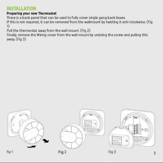
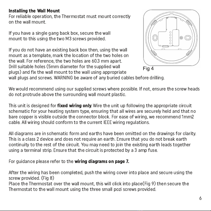
Installing the Wall Mount
For reliable operation, the Thermostat must mount correctly
on the wall mount.
If you have a single gang back box, secure the wall
mount to this using the two M3 screws provided.
If you do not have an existing back box then, using the wall
mount as a template, mark the location of the two holes on
the wall. For reference, the two holes are 60.3 mm apart.
Drill suitable holes (5mm diameter for the supplied wall
plugs) and fix the wall mount to the wall using appropriate
wall plugs and screws. WAR I G be aware of any buried cables before drilling.
We would recommend using our supplied screws where possible. If not, ensure the screw heads
do not protrude above the surrounding wall mount plastic.
This unit is designed for
fixed wiring only
. Wire the unit up following the appropriate circuit
schematic for your heating system type, ensuring that all wires are securely held and that no
bare copper is visible outside the connector block. For ease of wiring, we recommend 1mm2
cable. All wiring should conform to the current IEEE wiring regulations.
All diagrams are in schematic form and earths have been omitted on the drawings for clarity.
This is a class 2 device and does not require an earth. Ensure that you do not break earth
continuity to the rest of the circuit. You may need to join the existing earth leads together
using a terminal strip. Ensure that the circuit is protected by a 3 amp fuse.
For guidance please refer to the
wiring diagrams on page 7.
After the wiring has been completed, push the wiring cover into place and secure using the
screw provided. (Fig 8)
Place the Thermostat over the wall mount, this will click into place(Fig 9) then secure the
Thermostat to the wall mount using the three small pozi screws provided.
6

WIRING DIAGRAMS
7

8
TESTING THE SYSTEM
Thermostat must not have a Thermostat Radiator Valve (TRV)
fitted to the radiator(s)
ONLINE SETUP WIZARD
*** You will need to be in the same location as the inspire system to complete the initial setup ***

9
YOUR THERMOSTAT
Adjustment
Keys
Current Central
Heaing Function
WiFi Signal
Strength
Call for Heat
Indicator
Temperature
Time
Current Hot
Water Function
9

BASIC FUNCTIONS (HEATING)
Off
Your heating will be switched off.
Auto
Your heating will follow your Temperature Profile
The default is: (This can be adjusted via your online account)
15 Degrees between 00:00 and 06:00
20 Degrees between 06:00 and 08.30
17 Degrees between 08:30 and 17:00
22 Degrees between 17:00 and 22:30
15 Degrees between 22:30 and 00:00
Man
Your heating will be switched on and keep your property at the set temperature.
Boost
This is used if you would like to switch your heating on for a set period of time.
The default is 1 hour at 20 degrees. When pressed, ‘BOOST CH’ will flash to indicate that boost is
currently active.
Your heating will switch on for the programmed length of time, at the programmed Boost
Temperature (If set.) After this time has expired, the Thermostat will return to the previous
state.
Adjusting the Temperature (not applicable when in Off)
Use the ‘/\’ and ‘\/’ buttons to set the desired room temperature.
Pressing the ‘CH MODE’ key will cycle through the above modes.
Program Advance
This is used if you would like to ‘jump’ to the next profile temperature. Press the ‘ADV CH’ key to
‘jump’ to the next Temperature in your schedule. It will only have an effect if the Thermostat is
in auto mode. Pressing the ‘ADV CH’ key a 2nd time will cancel the program advance and the
unit will revert back to the current profile set temperature. 10

BASIC FUNCTIONS (HOT WATER)
Off
Your hot water will be switched off.
Auto
Your hot water will follow your profile times.
The default is: (This can be adjusted via your online account)
On between 06:00 and 08.30
On between 12:00 and 13:00
On between 18:00 and 20:00
Man
Your hot water will be switched on and will keep your hot water cyclinder at the temperature set
by your tank stat.
Boost
This is used if you would like to switch your hot water on for a set period of time.
The default is 1 hour. When pressed, ‘BOOST HW’ will flash to indicate that boost is currently
active.
Your hot water will switch on for the programmed length of time. After this time has expired, the
hot water function will return to the previous state.
Adjusting the Mode
Pressing the 'HW MODE' key will cycle through the above modes.
Program Advance
This is used if you would like to ‘jump’ to the next scheduled hot water setting. Press the ‘ADV
HW’ key to ‘jump’ to the next setting in your schedule. It will only have an effect if the hot water
function is in auto mode. Pressing the ‘ADV HW’ key a 2nd time will cancel the program advance
and the unit will revert back to the current profile setting.
11

SETTING THE CLOCK
If you have an Internet connection, this will be done automatically. If you are outside of the
United Kingdom. you can specify your time zone on the ‘Setup’ page within your online
account. To set the clock manually, press the ‘BOOST CH’ and ‘BOOST HW’ keys to enter the
menu. Use the ‘+’ and ‘-’ keys to set the hours, then press ‘ADV CH’ this will take you to the
minutes and then the days (1 = Sunday, 7 = Saturday) which are set in a similar way. To exit the
menu press the ‘BOOST CH’ and ‘BOOST HW’ keys simultaneously.
SETTING UP YOUR ACCOUNT
Please check what version you have on the below list and follow the weblink for more
information.
Residential
– www.inspirehomeautomation.co.uk/residential
Landlord
– www.inspirehomeautomation.co.uk/landlord
Calendar
– www.inspirehomeautomation.co.uk/calendar
PHONE APP
Please go to this weblink to download the app www.inspirehomeautomation.co.uk/apps
TROUBLESHOOTING
Please visit our website for more information on trouble shooting:
www.inspirehomeautomation.co.uk/help
Please check out our
FAULT FINDING GUIDE
and
FAQ
for assistance, there will also be
information here on how to contact us.
Please leave this manual with the user.
12
Table of contents
Other Inspire Thermostat manuals

Inspire
Inspire NS1002-1CH User manual

Inspire
Inspire ignite User manual

Inspire
Inspire NS1001 User manual

Inspire
Inspire NS1003 User manual

Inspire
Inspire NS1001 Plus Zones User manual

Inspire
Inspire ignite User manual

Inspire
Inspire NS1002 User manual

Inspire
Inspire ignite User manual

Inspire
Inspire NS1001 User manual
Popular Thermostat manuals by other brands

Vive Comfort
Vive Comfort TP-N-701 installation manual

Daikin
Daikin D2270C Owner's Manual & Installation Instructions

Pegler Yorkshire
Pegler Yorkshire Terrier i-Temp Handbook

Honeywell Home
Honeywell Home RTH7500 Series Quick installation guide

tado°
tado° RU01 Technical documentation

Sinope
Sinope TH1134ZB installation guide