5
Tools Required (Not supplied)
Philips screwdriver
Flat blade screwdriver
Long nosed pliers
BS4662 back box
Isolate the existing supply, then remove the existing Programmer or external wireless receiver (if fitted).
Make a careful note of all wiring locations of the existing programmer before removing any wires. The
Relay Module will replace most existing programmers and wireless receivers on the market.
If your combi boiler has a built in wireless receiver, this should be removed by unclipping it from the front
panel. Similarly if you have an existing integral timer, you may wish to consider removing this, or simply
leave it switched to the “ON” mode.
Remove the front cover from the Relay Module, this should easily lift of the unit. If the unit has been
‘clicked’ in place, then grip the recessed part of the rear and pull the chrome part of the front cover off.
Pull out the control panel from the wall mount by placing two fingers
on either side whilst holding the wall mount and pulling apart.
Then secure the wall mount onto the single or double gang back box using the two M3 screws provided.
If you are not using an existing back box then you will either need to
sink a backbox into the wall, or use an external back box. You can
find these in all good hardware stores.
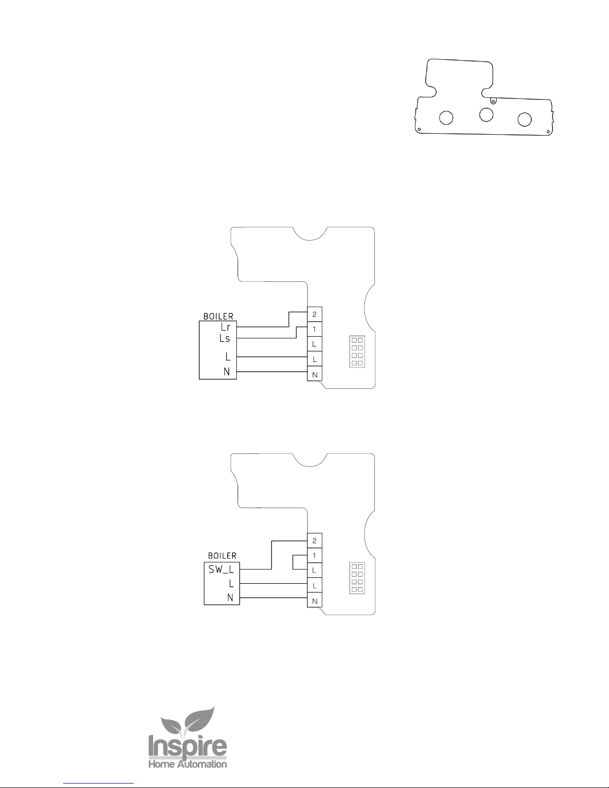
This unit is designed for fixed wiring only. Wire the unit up following the appropriate circuit schematic
for your heating system type, ensuring that all wires are securely held and that no bare copper is visible
outside the connector block. For ease of wiring, we recommend 1mm2cable, although 1.5mm2 can also
be used. All wiring should conform to the current IEEE wiring regulations. When replacing an existing
programmer, the wiring conversion table, on the back cover, may be of assistance.
All diagrams are in schematic form and earths have been omitted on the drawings for clarity. The NS1002
is a class 2 device and does not require an earth. Ensure that you do not break earth continuity to the
rest of the circuit. You may need to join the existing earth leads together using a terminal strip. Ensure
that the circuit is protected by a 3 amp fuse.
Installation - Relay Module