Insta 60031020 User manual

Operating instructions
Power supply 160 mA
Art. no. 60031020
Power supply 320 mA
Art. no. 60032020
Power supply 640 mA
Art. no. 60033020
Power supply 1280 mA
Art. no. 60034020
31.03.2023
8259733x
Insta GmbH
Postfach 1830
58468 Lüdenscheid
Germany
Telefon +49 (0) 2351 936-0
www.insta.de

Table of Contents
1 Safety instructions.............................................................................................................3
2 Device components...........................................................................................................3
3 Function ............................................................................................................................4
4 Operation ..........................................................................................................................5
5 Information for electrically skilled persons ........................................................................6
5.1 Mounting and electrical connection........................................................................ 6
6 Technical data.................................................................................................................10
7 Warranty..........................................................................................................................11
2 / 11
8259733x 31.03.2023
Power supplies

1 Safety instructions
Electrical devices may only be mounted and connected by electrically skilled
persons.
Serious injuries, fire or property damage possible. Please read and follow manual
fully.
Danger of electric shock. During installation and cable routing, comply with the regu-
lations and standards which apply for SELV circuits.
This manual is an integral part of the product, and must remain with the end cus-
tomer.
2 Device components
Image1: View
Image2: 1280 mA voltage supply – view
Power supplies
3 / 11
8259733x 31.03.2023

(1) Connection of mains
(2) LED Betrieb, green
On: Normal operation
Flashes: Overload or overvoltage
Off: No mains voltage or internal error
(3) LED Überlast, red
On: Overload or short-circuit on KNX bus line or output DC 30 V
(4) LED Überspannung, yellow
On: Overvoltage on KNX bus line or output DC 30 V
(5) Output DC 30 V
(6) Output Bus for KNX bus line
(7) LED Reset, red
Flashes rapidly 2.5 Hz: Reset for 20 seconds
Flashes slowly 0.25 Hz: Permanent reset
(8) Button Reset
Acknowledge the diagnostic message: Press briefly, < 0.5 seconds
Switch off the KNX bus line for 20 seconds: Press between 2...4 seconds
Permanently switch off the KNX bus line: Press longer than 4 seconds
Terminate the permanent reset: Press the button
(9) Signal contact for diagnostic message
Closed: Normal operation
Open: After overload, overvoltage or in case of a KNX power failure
3 Function
System information
This device is a product of the KNX system and complies with the KNX directives.
Detailed technical knowledge obtained in KNX training courses is a prerequisite to
proper understanding.
Intended use
– Supplying KNX devices with bus voltage
– Supplying devices with direct current
– Mounting on DIN rail according to EN 60715 in sub-distribution unit
Product characteristics
– Output with integrated inductance for supplying KNX bus lines
– DC 30 V output for supplying additional devices
– Nominal current can be subdivided to outputs as desired
– Reset button
– Short-circuit proof
– Overvoltage proof
Power supplies
4 / 11
8259733x 31.03.2023

– No-load proof
– Suitable for operation in systems with emergency power supply
– Potential-free signal contact for operating and diagnostic message
– Two identical power supplies can be connected in parallel (with the versions
160 mA, 320 mA and 640 mA)
4 Operation
Acknowledging the diagnostic message
After detecting a overvoltage or a short circuit the LED and the signal contact signal
the event until the message is acknowledged.
■ Press the Reset button for less than 0.5 seconds.
LED functions and signal contact
LED
Betrieb (2),
green
LED
Überlast (3),
red
LED
Überspan-
nung (4), yel-
low
LED
Reset (7),
red
Signal con-
tact (9)
Normal op-
eration
on off off off closed
Reset for
20 seconds
on off off flashes
2.5 Hz
closed
Permanent
reset
on off off flashes
0.25 Hz
closed
Overvoltage flashes
0.5 Hz
off on (until the
message is
acknow-
ledged)
off open (until
the message
is acknow-
ledged)
Overload,
short-circuit
flashes
0.5 Hz
on (until the
message is
acknow-
ledged)
off off open (until
the message
is acknow-
ledged)
KNX voltage
failed / in-
ternal error
off off off off open
In normal operation, control of the voltage supply is not necessary. The button (8) is
recessed and thus prevents that it is inadvertently actuated in operation.
Reset function and Reset button
When a bus segment is reset, the output voltage of the voltage supply is switched off.
At the same time the bus line is short-circuited so that all connected bus devices are
disconnected from the bus voltage.
Power supplies
5 / 11
8259733x 31.03.2023

Resetting the bus line for 20 seconds
■ Press the Reset button (8) between 2 ... 4 seconds.
The bus line is short-circuited for 20 seconds.
The LED Reset (7) flashes quickly.
After 20 seconds the bus voltage is switched on again and the LED Reset
switches off.
Permanently resetting the bus line
■ Press the Reset button (8) for more than 4 seconds.
The bus line is short-circuited.
The LED Reset (7) flashes slowly.
Terminating the permanent reset
Prerequisite: The bus line is permanently reset, the LED Reset (7) flashes slowly.
■ Press the Reset button (8).
The bus voltage is switched on again and the LED Reset switches off.
5 Information for electrically skilled persons
DANGER!
Electric shock when live parts are touched.
Electric shocks can be fatal.
Before working on the device, disconnect all corresponding circuit breakers from the
supply voltage, secure against being switched on again and check that there is no
voltage!
5.1 Mounting and electrical connection
Mounting the device
Observe the temperature range. Ensure sufficient cooling.
■ Mount the device on DIN rail. The terminals for the mains connection (1) must
be at the top.
Power supplies
6 / 11
8259733x 31.03.2023
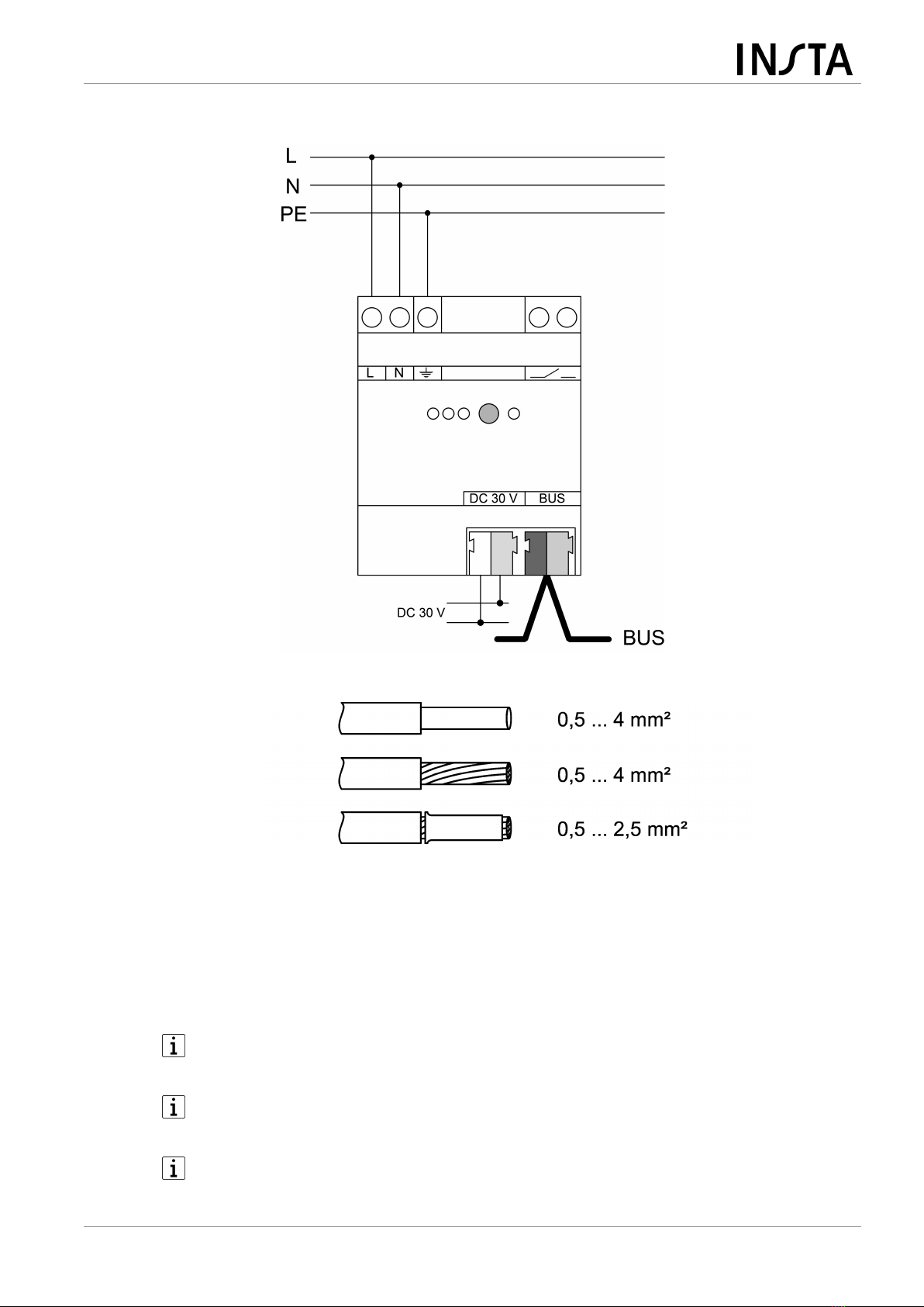
Connecting the device to mains voltage and bus
Image3: Wiring example – mains voltage and bus line
Image4: Clampable conductor cross-section
■ Connect the mains voltage to the terminals L and N (1).
■ Connect the protective conductor PE to the terminal Ʈ.
■ Connect the KNX bus line to output Bus (6).
■ Install the cover to protect the bus connection against hazardous voltages in
the connection area.
The total load of the outputs can be subdivided as desired. Do not exceed the
total rated current.
Do not connect any other products to the bus output. This might influence the
bus communication.
If required, an identical voltage supply can be connected in parallel for the
device variants 160, 320 and 640 mA.
Power supplies
7 / 11
8259733x 31.03.2023
Connecting the diagnostic analyser
The voltage supply signals overvoltage, overload, short circuit and KNX voltage fail-
ure using a floating contact (9). A monitoring device can detect the switching status
and forward it for diagnostic purposes.
The signal output serves only for signalling purposes and may not be used as
a load output.
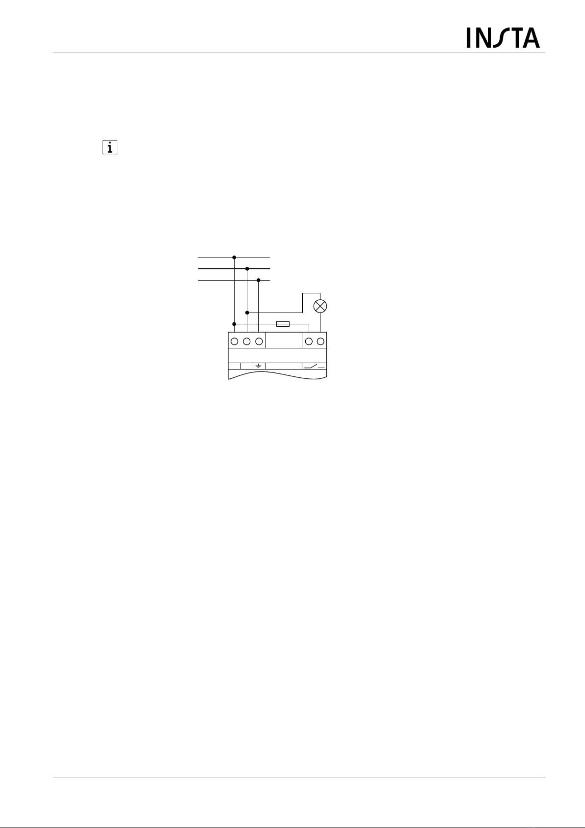
A signal lamp, a signal relay or, e.g., a KNX binary input connected to a KNX bus line
can be used as monitoring device.
■ Connect the signalling device according to the connection example
(see figure 5).
L N
L
N
PE
max. 2 A
Image5: Application example – signal lamp for optical operating display
■ Connect the KNX binary input according to the connection example
(see figure 6).
Power supplies
8 / 11
8259733x 31.03.2023

Image6: Application example – KNX binary input on main line for detecting and cent-
rally signalling diagnostic messages
Observe the wiring! Install the cables for the signal contact such that no loops
are created. During operation loops can cause interference voltages to be
coupled into.
The signal contact indicates a power failure on the KNX line. When voltage
supplies are connected in parallel, the signaling contact opens only if both
voltage supplies are faulty or switched off (e.g. due to failure of the mains
voltage on both devices).
In this case too, the green operation LED will not extinguish until both power
supplies are switched off.
Operation with emergency power systems
The voltage supply can be used in combination with centrally supplied emergency
power systems. In this way, the function of the KNX system and the control of the
most important functions can be ensured in emergency operation.
Statutory and standard specifications for emergency power and emergency
lighting systems vary from country to country. In any event, the user / technical
planner must check whether the specific specifications are observed.
Cable lengths
For KNX line segments and power supplies the following rules apply:
Power supplies
9 / 11
8259733x 31.03.2023

– Bus line length per line segment: Max. 1000 m
– Bus line length between voltage supply and KNX bus subscriber: Max. 350 m
– Bus line length between two KNX bus subscribers: Max. 700 m
6 Technical data
Rated voltage AC 220 ... 240 V ~
The device is operable in the range of
180 V AC … 264 V AC.
Mains frequency 50 / 60 Hz
Power loss (max. load on all outputs)
Art. no. 60031020 max. 1.5 W
Art. no. 60032020 max. 1.8 W
Art. no. 60033020 max. 2.9 W
Art. no. 60034020 max. 6.4 W
Efficiency
Art. no. 60031020 approx. 76%
Art. no. 60032020 approx. 84%
Art. no. 60033020 approx. 87%
Art. no. 60034020 approx. 86%
Rated voltage DC DC 240...250 V
KNX
KNX medium TP256
Bus output voltage DC 28 ... 31 V SELV
Output current
Art. no. 60031020 160 mA (all outputs)
Art. no. 60032020 320 mA (all outputs)
Art. no. 60033020 640 mA (all outputs)
Art. no. 60034020 1280 mA (all outputs)
Short-circuit current
Art. no. 60031020 max. 1 A
Art. no. 60032020 max. 1 A
Art. no. 60033020 max. 1.5 A
Art. no. 60034020 max. 3 A
Connection type for bus Device connection terminal
Parallel operation with identical power
supply
Art. no. 60031020 Yes
Art. no. 60032020 Yes
Art. no. 60033020 Yes
Art. no. 60034020 No
Power supplies
10 / 11
8259733x 31.03.2023
This manual suits for next models
3
Table of contents


