PSN-1000 POWER EXPANDER-5403599-REV C-04/17
2
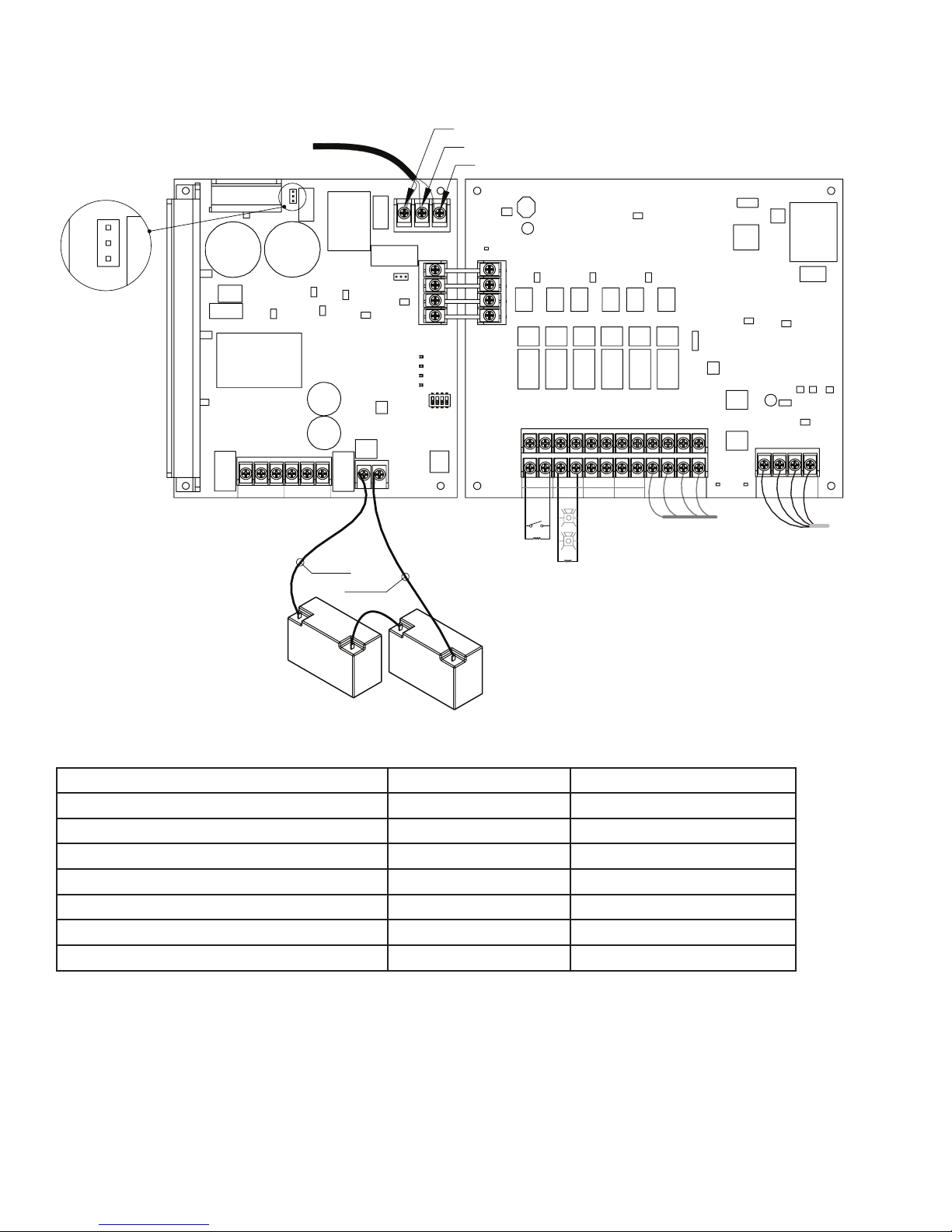
1. Installation Wiring Document
Type of Circuit Voltage Type Power Type
AC Connection High Voltage Non-Power Limited
Battery Connection Low Voltage Non-Power Limited
Trouble Relay Low Voltage Non-Power Limited
Low AC Relay Low Voltage Non-Power Limited
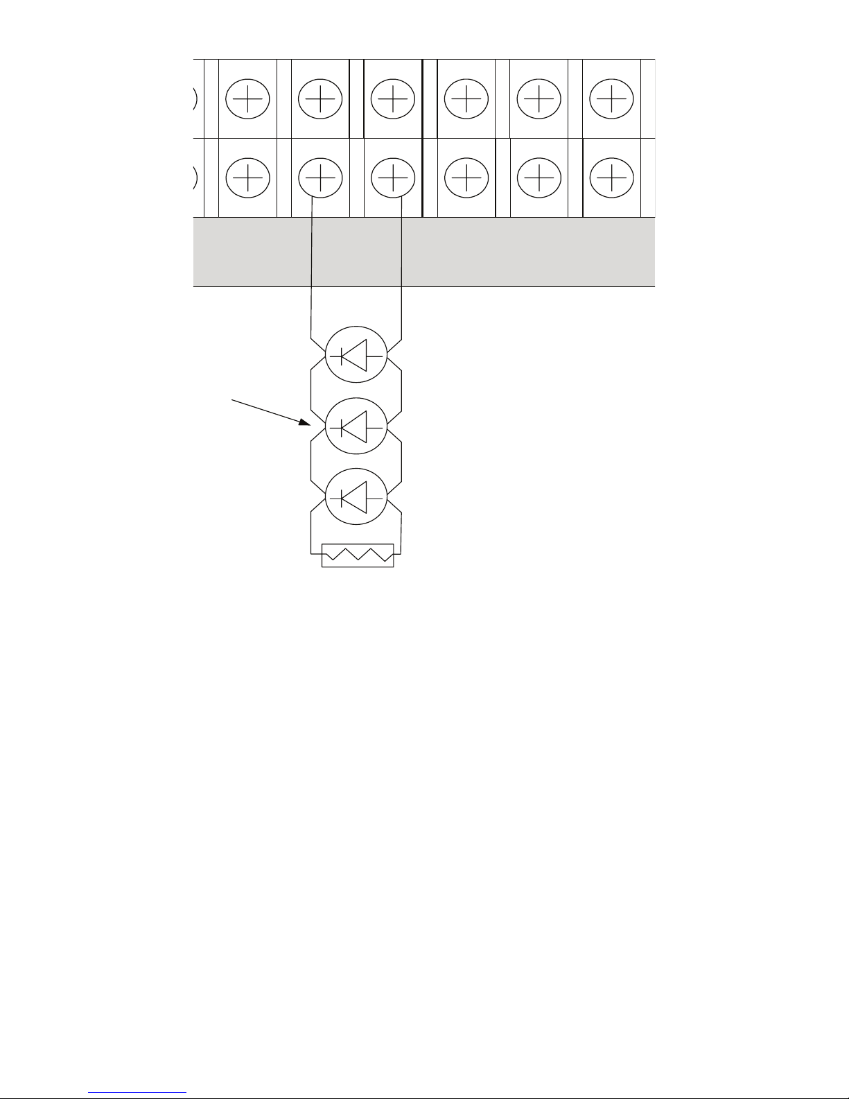
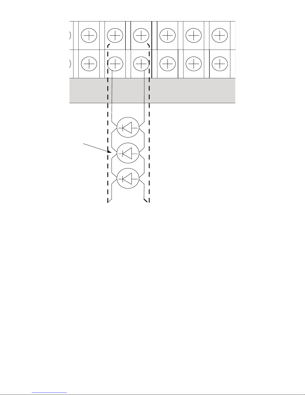
Notication Device Circuits (NACs) Low Voltage Power Limited
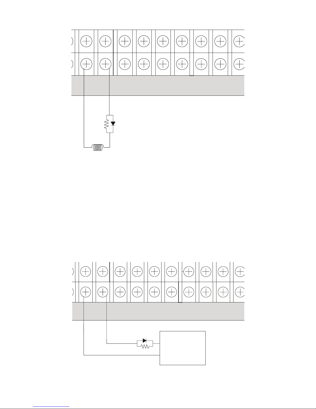
Input Circuits Low Voltage Power Limited
Plink RS-485 Connections Low Voltage Power Limited
P-LINK FROM
CONTROL PANEL
P-LINK REPEATER
E.O.L.
E.O.L.
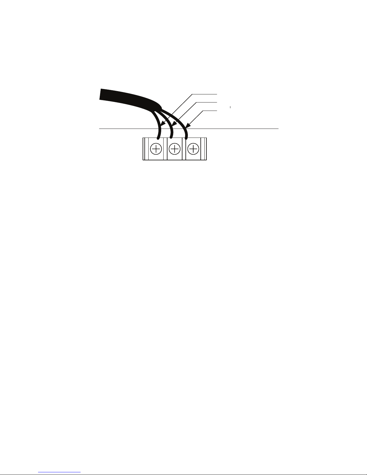
GROUND
WHITE
BLACK
Battery connection (non-power limited).
Use two (2) 12V batteries connected in series.
PSN-1000
POWER SUPPLY
P/N 5409083-B (12/21/2016)
120VAC 50Hz~60Hz
240VAC 50Hz~60Hz
Connect to separate
unswitched AC circuit
FUSE
120|240
Common relays are
non-power limited.
TROUBLE
NC COM NO
LOW AC
NC COM NO
BATTERY -
BATTERY +
Primary AC
120VAC 50Hz~60Hz, 5.1 AMP
Min Low AC Detect 98VAC
240VAC 50Hz~60Hz, 2 AMP
Min Low AC Detect 194VAC
Common Relays
3A @ 125VAC (Resistive)
3A @ 30VDC (Resistive)
Battery Charging
27.3VDC @ 1A
Low Battery Detect @20.4VDC
Earth Fault to Any Terminal
0 Ohms
Fuse Specification
8A-250VAC Time-Lag
- I2 +
- I1 +
- NAC2 +
- NAC1 +
- NAC4 +
- NAC3 +
- NAC6 +
- NAC5 +
- +
IN
A B
P-LINK
- +
OUT
A B
RPTR
COMM
MAIN
COMM
BULK
COMM
P-LINK
- +
A B
120/240 VAC
Jumper Position
F.C.C.
This device has been veried to comply with FCC Rules Part 15,
Class A Operation is subject to the following conditions:
1. This device may not cause radio interference.
2. This device must accept any interference received including any
that may cause undesired operation.
Requirements
CAUTION:
De-Energize Unit Prior to Servicing
System must be fully tested after installation.
Intended for indoor use in dry locations only.
Separation of power limited wiring from non-power limited wiring must be at least 1/4".
Install in accordance with installation manual Part Number 5403599 Rev __,
NFPA 70, 72, 12, 12A, 13, 15, 16, 17, 17A, 750, 2001