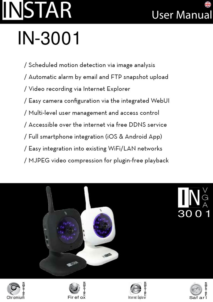
Instar IN-MOTION 300 User manual

Android
iPhone
LINUX
Mac OS
Windows
Motion
300
/ Passive (Pyroelectric) Infrared Motion Detection
/ Easy Installation with your INSTAR IP Camera
/ 90 Degrees Conical Detection Zone
/ Pulse Count Compensation to prevent false Alerts
/ Compatible with all INSTAR Cameras featuring an Alarm I/O
IN-MOTION 300
Quick Installation Guide

Motion
300

INSTAR
Quick-Installation Guide
IN-Motion®300 PIR Motion Detector
e following topics will be shortly explained in this Quick-Installation Guide:
1. SAFETY WARNING..........................................................................2
2. THE PIR SENSOR.............................................................................3
3. BASICSETUP.....................................................................................5
4. HOW DOES IT WORK?...................................................................7
5. INSTALLATION................................................................................9
6. TECHNICAL DATA........................................................................10
7. DISPOSAL AND WARRANTY.......................................................11
More information can be found
on our homepage
www.instar.de
is Quick-Installation Guide
was made exclusively for INSTAR customers.
Your Manufacturer of Network and Security Equipment

is device suites the basic requirements of the European regulations for electro-
magnetic compliance (2004/108/EC) and the low voltage regulations (2006/95/EC ).
CE-Conformity
Safety Warnings 1
l
Please read the following safety instructions carefully and keep them in a safe
place.
»Make sure the device is not operated near any hot surfaces.
»is device shall not be used by people (including children) with limited
physical, sensory and mental capabilities. Only a trained person that knows
how to use the device carefully can use the device.
»Children should be supervised to make sure they don’t play with the device.
»If the device casing is damaged, it can only be replaced by the manufacturer
or the customer service person or a similar qualied person to avoid any
damage to you and the device.
»When cleaning the device, please never place the device in water.
»Make sure you only install the device in a suitable power socket (100-240V).
»is device is for indoor use only!
»Never install the device near explosive or ammable substances.
»Don’t use the device for any other purpose that it isn’t made for.

2 The PIR Sensor
l
7
1
2
3
4
5
6
1 Relay Jumper Allows you to set the relay to “Normally Open” (1&2)or
“Normally Closed” (2&4). In NC mode an interruption
in the connection to the sensor, e.g. when it is damaged,
will lead to an alarm. NC is the standard mode.
2 Alarm Indicator
Jumper
Set the Jumper to the pins 2&3 to deactivate the red
alarm indicator LED (see 7, below).
3Tamper Switch e tamper switch will cause an alarm in case the sensor
is opened to avoid manipulation.
4 Connection
Terminal
Connector for the 12V power supply + alarm output.
5 Pulse Compen-
sation Jumper
In case your sensor triggers too many false alarms, please
adjust the sensors sensitivity - Jumper on Pin 1&2 equals
a high sensitivity, 2&3 an average sensitivity and remov-
ing the jumper leads to a low sensitivity.
6 IR Sensor Dual element pyroelectric detector.
7 Alarm Indicator e red shows LED the alarm state of the sensor.

What is PIR?
PIR stands for Passive Infrared or Pyroelectric Infrared. PIR sensors can be dened
as detectors of warm-bodied targets in motion. A stationary target can not be de-
tected. To detect a moving target, the target must have a surface temperature that is
substantially dierent than the surrounding ambient temperature. Although the
usual targets of a PIR detector are warm-bodied (mammals, birds), the PIR sensor
will also detect a moving target that has a surface temperature that is signicantly
lower than the ambient temperature. As long as the target is large enough, and its
surface temperature is detectably dierent than the ambient (higher or lower) - and
the target is moving - it can be detected by a PIR sensor.
General Considerations
Main Features:
Temperatures can oen change dramatically in relatively short times. Large tem-
perature changes can render the PIR sensor either more, or less, sensitive. As am-
bient temperatures rise to near 37ºC, the dierence between the target and ambient
temperature decreases - and the sensitivity of the sensor declines. As temperatures
decrease the opposite is true and the sensor becomes more sensitive.
As target and ambient temperatures become equal, the PIR sensor may no longer be
able to detect a target. Large targets usually have enough variation in their surface
temperature to allow the sensor to detect them - even when the ambient tempera-
ture is the same as their average body temperature.
e IN-Motion PIR sensors compensate the PIR detector sensitivity according to
the ambient temperature. is allows you to utilize the full range of the sensors
capabilities - whenever and wherever they are needed!
• Internal logic control to avoid false alarms
• Auto temperature compensation
• Pulse count adjustment
• White light interference compensation
• RF interference comp. (20V/m-1GHz)
• Wide angle Fresnel lense
• Ceiling installation
• Alarm output N.C. / N.O.

e IN-Motion PIR Sensor is already connected to the power plug and the alarm
output cable. Simply connect the signal cable to your INSTAR cameras alarm input
connector. e image below shows the I/O bridge of IN-3005/3010 or 3011 - choose
the ports 3 & 4 for the sensor cable and replug the bridge into the cameras I/O
connector.
e alarm input of your camera might look dierent depending on your camera
model. Please refer to your user manual to identify the correct ports. You may
choose either polarity when connecting the cable - please refer to the next page for
information on how to adjust the cameras trigger level accordingly.
How to connect your IN-Motion Sensor to your camera ?
3 Basic Setup
l

Aer connecting the PIR sensor with your camera’s signal input, please open
the camera’s web userinterface. Go to the alarm settings and activate the ex-
ternal alarm input:
Depending on the polarity you choose for connecting the sensor’s signal cable
to the camera, you might receive a constant alarm trigger. Please adjust the
Alarm Trigger Level / Relay Position accordingly:
Triggering the PIR sensor (red alarm indicator should light up when triggered,
see page 3/ #7) should now trigger an alarm event inside of the camera. e
trigger event will be treated just like an internal motion detection event by the
camera. So all the settings in place for an alarm event (video recording, email
notication, p upload, etc) can be triggered by the PIR sensor from now on.

4 How does it work?
l
What do I need to consider before installing the sensor ?
e standard sensor coverage area is approximately conical in shape and is
broken up into zones by the Fresnel lense - see below for a top view of cover-
age area. e target to be detected must pass either into or out of one of these
zones in order to be detected. Small targets can sometimes move between
these zones and not be detected because they never pass into or out of a zone.
Sensor Coverage Area
Top View
Sensor Coverage Area
Side View
Targets moving directly toward or away from the sensor may sometimes es-
cape detection as PIR sensors tend to be less sensitive to this type of movement
- this is most likely to occur with small targets.
While not an absolute requirement, for the best results a target should move
across the coverage area. Note how the zones are spaced wider near the end of
the sensors range, and are shorter at the edges of the coverage area. At the far
end of the detection area the sensor is covering the largest number of square
feet. As you move closer to the sensor its coverage area decreases. A small tar-
get near the end of the sensors range crosses only a tiny percentage of the total
covered area and might escape detection. A small target close in to the sensor
crosses a greater percentage of the covered area and is much easier to detect. A
target’s size, distance from sensor, and surface temperature play an important
part in the sensors eective range.

e greatest drawback of the PIR sensor is that it will detect anything that is mov-
ing - air, shadows, grass, etc - and has a temperature diering from ambient. Many
schemes have been tried to minimize this problem, but in harsh outdoor settings,
some “falsing” is unavoidable. Below are some tips to help you minimize false
events.
Point the sensor away from the rising or setting sun. In general, North or South
works well, but your local site conditions could dictate otherwise.
Keep the sensor aimed at an area that will not have intense, direct sunlight warm-
ing all or part of the detection area. Shadows of trees or clouds moving across a
sun-warmed area can cause a momentary temperature drop which could cause
a false event to be recorded. Warmed air rising from the ground can cause prob-
lems too.
Wind can also cause movement of the object you have your sensor mounted to.
Make sure to secure your sensor to an object that will not sway in strong winds.
Any movement of the equipment may be interpreted as motion by the sensor.
Wind can cause false events. e moving air might be warmer or cooler than the
background. Place the sensor in an area sheltered from strong winds.
If the area is known to have many small birds / mammals, you will surely get
many empty pictures, as these active, fast animals will oen leave the frame be-
fore a picture can be taken (also see Pulse Count Compensation, next page).
Even in a shaded area, keep the sensor pointed away from dense shrubs or trees
that can retain the days warmth. A warm evergreen or other dense shrub will
hold the days heat. If the air temperature drops at night - and the still warm shrub
moves in the wind, this movement could be detected.
Tall, sun-warmed grasses or other vegetation blowing in a breeze can be detected.
Point the sensor away from dense, sun-warmed vegetation which can trap heat.
Do not place the sensor in a location where direct, bright sunlight will fall on
the sensor window.
How do I minimize false alerts?

e IN-Motion PIR controller supports a PCC (Pulse Count Compensation) Mode
- allowing you to determine how many detections (or ‘pulses’) must occur in a giv-
en time period before an event recorded. e illustration below shows a simplied
concept of the PIR’s detection area, and its detection zones. When a target passes
an edge (see vertical dotted lines) between “zones”,
an electrical signal - or ‘pulse’ - is generated by the
sensor. As the target moves across the detection area,
several pulses are generated, one each time the target
passes a zone’s edge. Since larger targets will generally
cause a greater number of pulses in a shorter period
of time, PCC modes can be used to help eliminate
small animals from being detected.
Sensor Detection Zones
Turn the detector counterclockwise and remove
the front cover. en simply use the two screws
and anchors included in the package to mount
the sensor parallel to your wall or ceiling. Close
the lid aerwards and you are good to go.
Aer turning on the power the sensor will start
a self-test that takes about 60s, indicated by the
red LED light. In normal operation the red in-
dicates a trigger event. Please refer to page No.
3 #2 on how to deactivate the alarm indicator.
Set the Pulse Compensation Jumper (see page 3, #5) to pin 1&2
to set the PCC to one pulse (highest sensitivity), to pin 2&3 to
set it to 2 pulses and remove the jumper completely to set the
PCC to ignore all events that don’t generate at least 3 pulses.
5 Installation
l
Direction of Travel
PCC modes can also help reduce “falsing” in noisy environments (lots of wind,
sun-warmed vegetation, etc), since most false events do not cause more than one or
two pulses over a period of several seconds. Use PCC modes with care, as an overly
aggressive setting could reduce capture rates of valid targets.

Technical Data
Operating voltage D.C. 9V - 16V
Current comsuption 18mA @ DC12V
Detection distance Diameter - 8m (at a height of 3.6m)
Detecting angle 360 ° @ an opening angle of ~ 90°
Start-up time 60 seconds ( warm-up time up to 10
minutes in temperatures below -10°C !)
RF interference compensation 10MHz 1GHz 20V/m
Alarm indicator Red LED
Alarm output N.C. or N.O., DC 28V/100mA
Tamper output N.C., DC 28V / 100mA
Sensor Dual element pyroelectric sensor
Environment humidity 95% RH (no congelation)
Working temperature -10°C to +50°C
Installation mode Ceiling- or wallmount
Installation height 2.5 to 6m
Size 79 mm diameter / 23mm depth
Technical Data 6
l

7 Warranty & Disposal
l
WARRANTY
INSTAR oers a 2-year warranty on its products. During this time you can send in
your device for a free repair. is excludes devices used with third-party equipment
that has not been approved by INSTAR. e warranty is only valid for the original
hardware parts of the device.
If you are contacting our Service Team please keep the model ready.
If you want to send in your device for repair, please use the RMA form that came
with the device. If you don’t have this form you can also download it from www.
instar.de or contact the INSTAR Service Team.
Disposal of old electrical appliances
e European Directive 2002/96/EC on Waste Electrical and Electronic Equipment
(WEEE), requires that old household electrical appliances must not be disposed of
in the normal unsorted municipal waste stream. Old appliances must be collected
separately in order to optimize the recovery and recycling of the ma-
terials they contain and reduce the impact on human health and the
environment. e crossed out “wheeled bin” symbols on the product
reminds you of your obligation, that when you dispose of the appliance
it must be separately collected. Consumers should contact their local
authority or retailer for information concerning the correct disposal of
their old appliance.
You can nd your INSTAR SERVICE CENTER at the following destination:
Company:
INSTAR Deutschland GmbH Hotline: +49 69 5960 6997
Auf der Hostert 17 (Mo-Fr, 12–18 o’clock GMT+1)
65510 Hünstetten Bechtheim Internet: www.instar.de
Germany Email: support@instar.de

INSTAR
...........................................................................................
...........................................................................................
...........................................................................................
...........................................................................................
...........................................................................................
...........................................................................................
...........................................................................................
...........................................................................................
...........................................................................................
...........................................................................................
...........................................................................................
Quick Notes
Table of contents
Other Instar Security Sensor manuals
