Description of the units available
A loadcell transmitter is used to convert loadcell outputs into a standard instrumentation
analog signal such as 4-20mA or 0-10volts, it will also supply power to excite one or more
loadcells. The 6004MF has many additional features such as displays for mass and
programming, digital communications for direct connection to control computers and alarms.
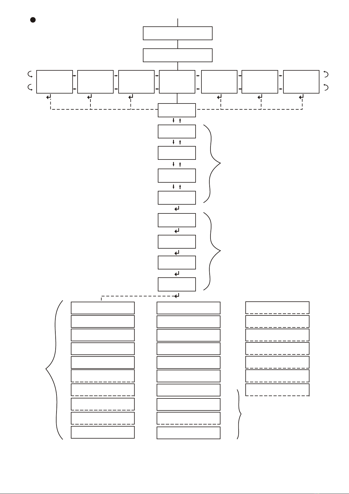
Our weighing electronics has always incorporated a precalibrate, zero trim and span trim
feature. This is a simple way to set up a strain-gauge loadcell system. All the variables, such
as sensitivity and range, are inserted in the precalibrate section so that the system is
reasonably accurate before adding test weights. The weighing system is then zero trimmed
(backbalanced) to offset the dead weight of weighbin, weighframe or weighbridge deck. With
known test weights the system can be span trimmed to get higher accuracy. In some
instances, such as very large weightanks where it is not possible to use test weights,
precalibration using factory test certificates for loadcell sensitivity results in an acceptable
overall system accuracy.
The ARM processor used incorporates a USB port and a real time clock with day/date. We
have made full use of these facilities and added an optional, factory fitted, global positioning
system (GPS) to cater for such applications as on-board truck weighing, positioning and data
logging. In refuse removal some countries are introducing legistration for customers to pay
by weight for this service. Farmers are starting to monitor crop production and fertiliser
distribution by location to improve farming efficiency. Logging contractors need to load for
maximum profit without incurring overweight fines.
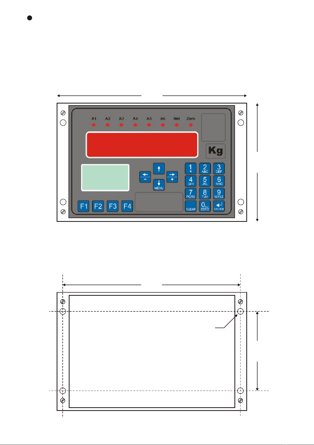
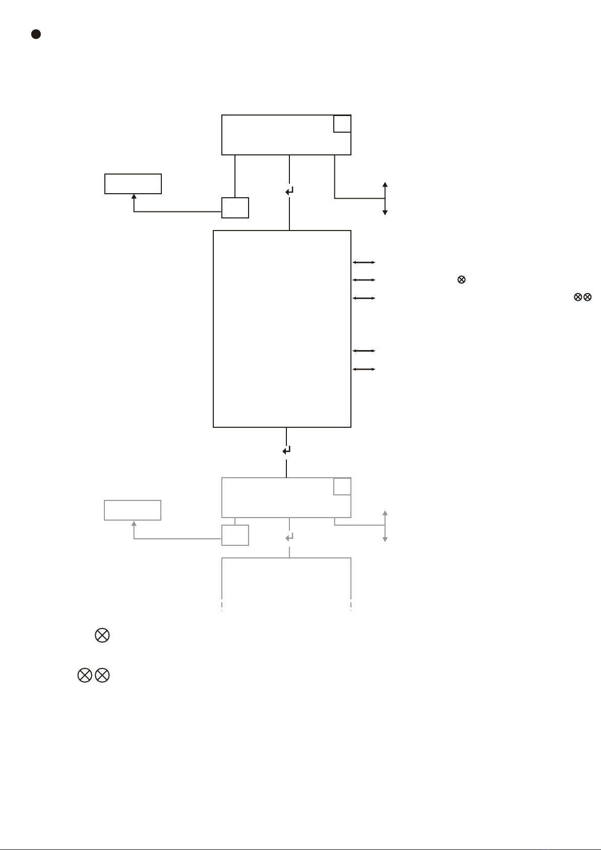
Loadcell transmitter
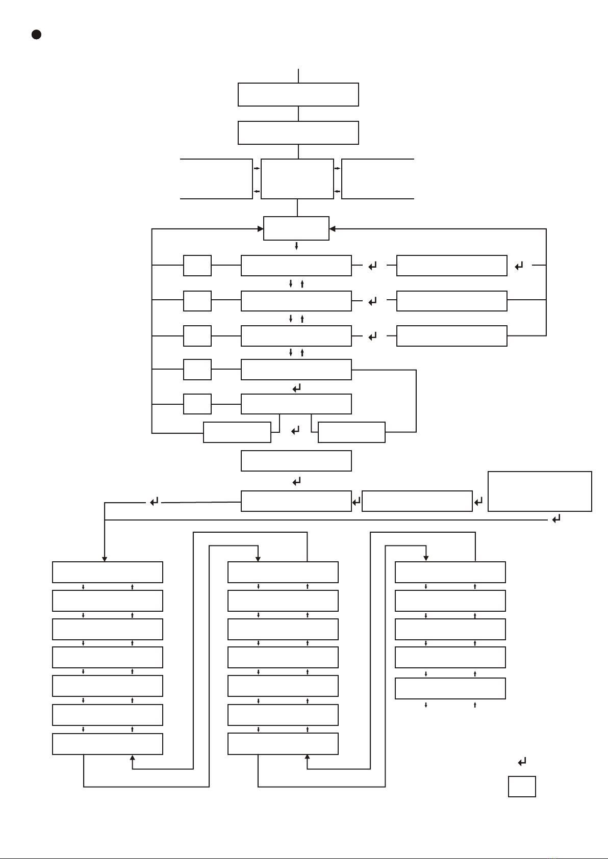
Loss-in-weight is becoming a popular form of mass flow measurement or control as it
requires few moving or wearing parts. Measure a weighbin over time and you can can get a
material flow rate either emptying or filling. Although we sample the averaged weight every
second you can select the measurement comparison period from 10 to 480 seconds. A short
period is ideal for small bins and extended time for larger weighbins. The system can be
selected to run for one weighbin cycle then stop or can be set to hold the rate display and
output whilst it refills the weighbin. Totalisers and selectable PI control are also standard
features.
Loss-in-Weight Transmitter
Page 4
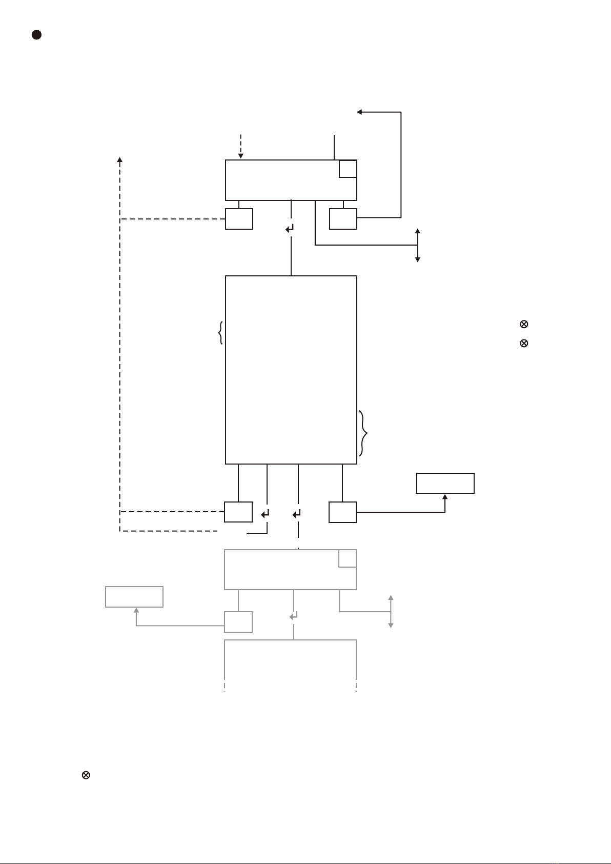
Belt Weigher
The belt weigher measures the weight of material on a conveyor belt and it's speed, from this
a mass flow is calculated in kg/min or tonnes/hr. The 6004BW allows you to set or measure a
belt speed, and, if measure, to set the pulley diameter, encoder pulses/rev and also to enter
the weighsection length. With this information and the precalibrate feature described above
the material flow rate will be calculated and displayed. Zero trim is selectable for length &
number of revolutions or time, and, if some form of check weighing is available, a rate
correction factor can be inserted. All rates have a main totaliser as well as a resettable
totaliser. The totaliser can be set for remote display through one of the setpoint outputs using
an optional photomos solid state relay which is ideal for this purpose. The PI control
selection used with a variable speed drive can convert the belt weigher into a flow controller.