INVISIBLE FENCE ICT 700 User manual

700 Series Transmitters
Computer Collar® Unit
Owner’s Manual
ICT 700
www.invisiblefence.com
1-800-578-DOGS

2 www.invisiblefence.com
Congratulations on your purchase of the world’s premier pet containment solution, the Invisible Fence®
Brand. The Invisible Fence Brand pet containment system is backed with a one-year, money-back
performance guarantee. The support of your Invisible Fence Brand Dealer gives you peace of mind that your
dog remains safe at home®. Refer to your warranty card or the back of your sales contract for complete details.
___________________________________________________
Table of Contents
Components ................................................................................................................................... 3
How the Systems Works ................................................................................................................... 3
Operating Guide ........................................................................................................................... 4
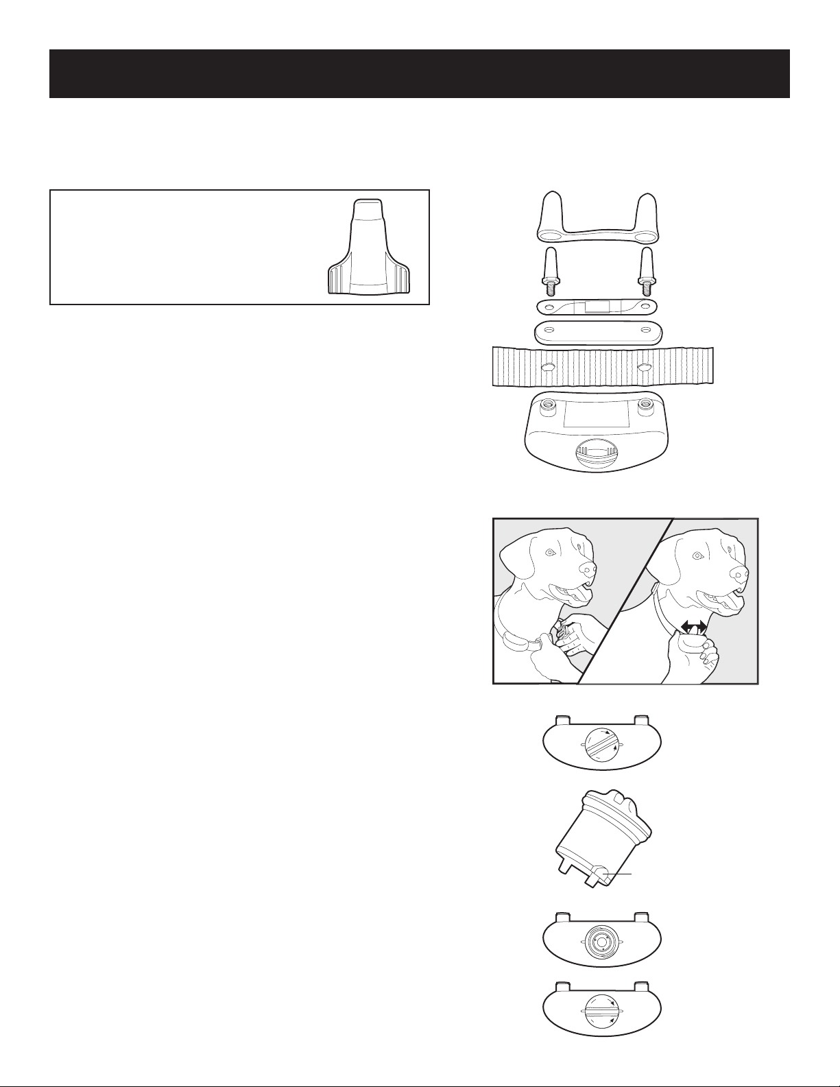
The Computer Collar Unit .......................................................................................................... 4
Fitting the Computer Collar Unit ................................................................................................ 4
Changing the Power Cap Unit .................................................................................................... 4
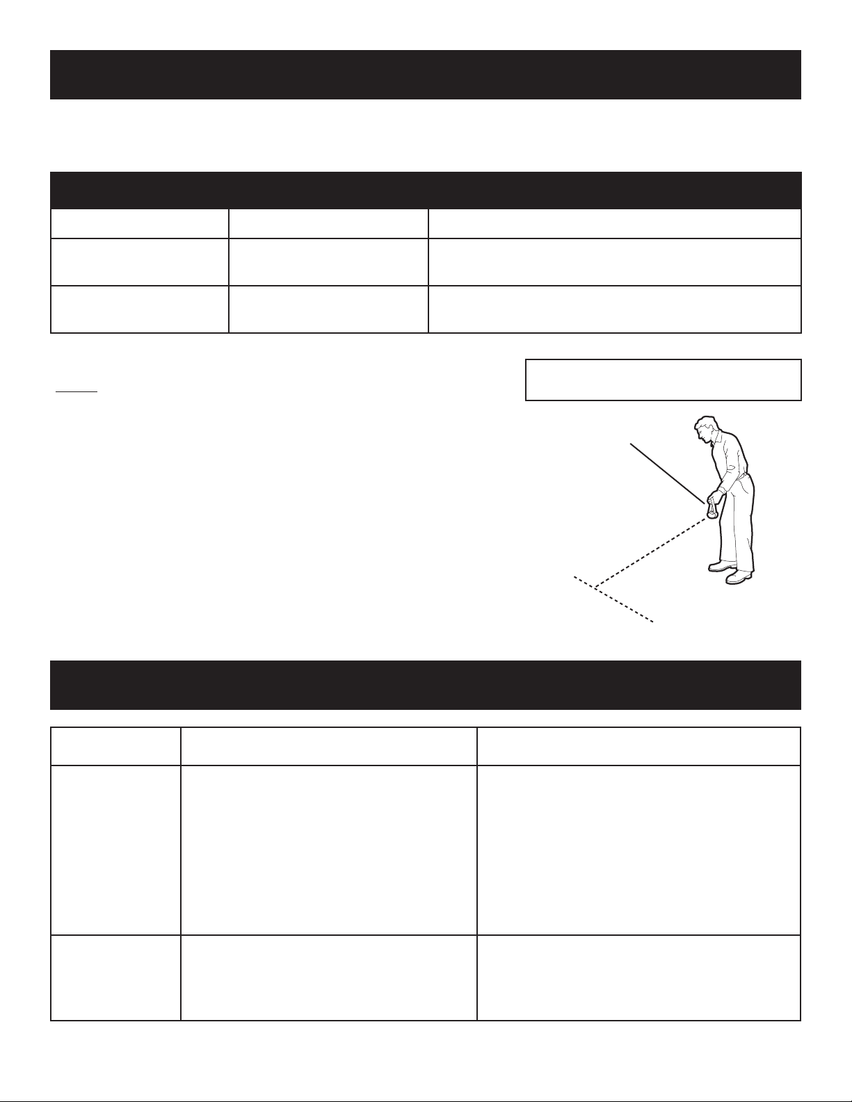
Power Cap Unit Tester ................................................................................................................ 5
Transmitter Status Indicators ...................................................................................................... 5
Maintenance Guide ...................................................................................................................... 6
Periodic Maintenance Check....................................................................................................... 6
Monthly Signal Field Width Test ................................................................................................. 6
Troubleshooting Guide ................................................................................................................. 6
Important Warnings ..................................................................................................................... 7
___________________________________________________
Important Precautions
1. Read and retain manuals: Read the entire Owner’s Manual and training instructions before using your new Invisible
Fence® Brand pet containment system.
2. Train your pet according to the instructions in the Invisible Fence Brand training manuals. Complete all steps before
allowing your pet to run free. Do not become overly confident if your pet has become conditioned to the Invisible Fence
Brand pet containment system sooner than expected.
3. Adhere to all cautions and warnings contained in any Invisible Fence Brand manual.
4. Do not attempt to service any Invisible Fence Brand equipment. Refer all service to your authorized Invisible Fence Brand
Dealer. Only your authorized Invisible Fence Brand Dealer should make adjustments to your pet containment system.
Unauthorized service or repair will void the warranty.
5. All Invisible Fence Brand pet containment systems are designed for domesticated animal use only. Never attempt to use
this product for any purpose not specifically described in this manual.
6. Check the Invisible Fence Brand transmitter periodically to make sure it is operating properly. Please refer to the chart on
page 4 for proper fitting instructions.
7. Check the tightness of the Computer Collar® unit on a regular basis. Remove your pet’s Computer Collar unit each night.
This will prevent the possibility of any irritation the collar may cause to your pet’s skin. However, if this is not possible,
please check the tightness of the collar each time you feed your pet by removing the collar and then replacing it back on
your pet. A condition called Pressure Necrosis, which is a devitalization of the skin due to excessive and prolonged contact
against the Correction Posts, may occur if the steps above are not followed.
8. If you have any questions about any aspect of your Invisible Fence Brand pet containment system, call your Invisible Fence
Brand Dealer immediately.
Dealer Name: _______________________
Dealer Phone: _______________________

www.invisiblefence.com 3
Components
Computer
Collar® unit
AC Adapter
Transmitter
ICT 700, 725, 750, and 775
Owner’s Manual
ICT 700
How the System Works
The 700 Series Transmitters are designed to work with an Invisible Fence® Brand R21v3.x or R51 Computer Collar® unit
to contain your pet within areas you choose, or teach your pet to avoid specific areas such as flower beds, gardens, or pools.
The transmitter produces a signal that travels along the signal field wire and back to the transmitter to produce an Invisible
Boundary® barrier.
When your pet approaches the established boundary, the Computer Collar unit generates a tone and correction to remind
your pet of the boundary. With training and praise, your pet will quickly learn to avoid the established boundary.
Note: A correction is a training term used to describe an action taken to discourage unwanted pet behavior. The Computer Collar® unit
applies a correction when your pet crosses the boundary of an Invisible Fence Brand electronic pet containment system. Corrections are
used in combination with rewards to alter unwanted pet behavior.
Your Invisible Fence® Brand pet containment system will only work when:
a. The transformer is connected to the transmitter and to a functional standard electric outlet, via an approved Lightning
Protection Device. All Invisible Fence Brand pet containment systems must be grounded per the National Electric
Code to be protected against lightning.
b. The transmitter is on, connected to the signal field wire, and producing a signal along the entire length of the wire.
c. The signal field wire is intact, continuous, and the transmitter’s Status Indicator light is blinking green.
d. The Computer Collar® unit is correctly fitted and worn by your pet. The Computer Collar unit must be adjusted so
that both of the correction posts touch your pet’s skin.
e. The Power Cap® unit in the Computer Collar unit is good and correctly installed. See page 4 and 5 for proper
Power Cap unit operation.
About Thunder and Electrical Storms: Even though your Invisible Fence® Brand pet containment system is equipped
with a Lightning Protection Device, it is still possible that it may be damaged during a thunderstorm, or when an electrical
storm is in the area. After a storm has ended, check the signal field width. See page 6 for periodic maintenance checks.

4 www.invisiblefence.com
The Computer Collar
®
Unit
The Computer Collar unit is a patented microprocessor-controlled device, powered by a patented Power Cap® unit.
Note: ONLY use the post tightening tool to
tighten the correction posts. Use of other tools
will void the warranty.
DO NOT secure the correction posts in the
Computer Collar unit with any kind of glue
or adhesive.
Fitting the Computer Collar Unit
To work properly, the correction posts on the Computer Collar unit
must touch your pet’s skin.
1. Position the collar strap high on your pet’s neck with the Computer
Collar unit under your pet’s lower jaw.
2. To avoid having a collar that is too tight on a thick-haired pet, thin
some hair away in order to allow the correction posts to make
contact with the skin. Do not shave the pet’s neck.
3. Tighten the collar strap of the Computer Collar unit appropriately.
Adjust the collar strap so it is snug enough to slide one finger
between a correction post and your pet’s neck.
4. Adjust the fit of the Computer Collar unit as necessary as your
pet’s coat, weight, and age change. Your pet’s coat may change from
season to season.
5. Allow your pet to become accustomed to its new Computer Collar
unit. The collar must be removed each night during the first month
of training. This ensures proper fit and avoids the possibility of skin
irritation.
6. After training is complete, remove your pet’s Computer Collar unit
each night if possible. This will help prevent irritation. However, if
this it not possible, please check the tightness of the collar each time
you feed your pet by removing the collar and then replacing it back
on your pet.
7. The Computer Collar unit is waterproof. If the nylon collar strap
becomes wet, it is recommended that it be removed from your pet
and be allowed to air dry before replacing the collar on your pet’s
neck.
Changing the Power Cap® Unit
1. Use a small, thin coin to remove the Power Cap® unit from the
Computer Collar unit. Insert the coin in the slot on top of the
Power Cap unit and turn it counter-clockwise. Do not push down
while turning. The Power Cap unit will rotate up and out of the
Computer Collar unit’s battery chamber.
2. Install a new Power Cap unit using the following steps:
a. Line up the lugs on the bottom of the Power Cap unit with
the grooves in the sides of the Computer Collar unit’s battery
chamber. Make sure the metal tabs on the bottom of the Power
Cap unit are not bent.
b. Place the Power Cap unit into the chamber while gently, but
firmly, turning it clockwise with your fingers.
Operating Guide
Correction Post Cover
Correction Post
Shunt (if needed)
Retaining Strip
Computer
Collar Unit
Collar
Strap
L
O
C
K
U
N
L
O
C
K
L
O
C
K
U
N
L
O
C
K
Alignment Lug
(one on each side)

www.invisiblefence.com 5
c. Use a small, thin coin in the slot on top of the Power Cap® unit to turn it clockwise until the slot on the top of the Power
Cap unit is lined up with the two small raised tabs on the bottom of the receiver. Do not over-tighten by turning the slot
past the tabs on the receiver.
On average, the Power Cap unit should be changed every 3 months. Low temperatures, the number of times the pet
challenges the pet containment system boundary, and improper collar fit can all reduce Power Cap unit life.
Note: The use of any power source other than a Power Cap unit will cause a receiver to operate erratically or fail. Failure of the receiver
due to the use of an unauthorized power source will void the warranty.
The use of unnecessary force may damage the case and render the Power Cap unit inoperable. NEVER open a Power Cap unit, dispose
of it in fire, recharge it, expose it to heat above 212°F (100°C), or expose its contents to water. Doing so can cause leakage or explosion
and may lead to personal injury.
Power Cap® Unit Tester
We strongly recommend that each customer obtain a Power Cap unit tester.
At least once a month, check the receiver battery with the Power Cap unit tester.
The Power Cap unit tester measures the internal resistance of a Power Cap unit and
shows how much life is left in the battery.
To test a Power Cap unit with the Power Cap unit tester, remove the Power Cap unit from
the receiver and put it into the Power Cap unit tester the same way that you would put it
into a Computer Collar® unit. If the battery is good, the green and red LEDs on the tester
will both light. If neither LED on the tester lights, or just the red LED lights dimly, the
Power Cap unit needs to be replaced.
BATTERY AND TESTER MUST
BE AT ROOM TEMPERATURE
TEST FOR 5 SECONDS
Replace battery when green light
is out and red light is dim or out.
Invisible Fence, Inc.
Green Red
Transmitter Status Indicators
Status Indicator Light: This is the only light visible outside the transmitter. The chart below explains the various Status
Indicator Light conditions.
Audible Alarm: There is an audible alarm for certain alert conditions (see chart below).
ICT 700
Status Indicator Light
700 Series Transmitter
Status Light and Audible Alarm Troubleshooting
Status LED Color Indicator Alarm
System OK Green Slow green flash:
1 sec. on, 4 sec. off
None
AC failure (operating on backup battery)
if applicable
Red Slow red flash:
1 sec. on, 4 sec. off
None
Loop wire break Green Steady green light Constant beeping
Defective or low backup battery Red Steady red light 1 second beep every minute

6 www.invisiblefence.com
Maintenance
Your Invisible Fence® Brand Dealer has professionally installed your pet containment system and ensured it is working
properly. You will want to perform periodic maintenance checks to make sure the system is properly functioning for your
pet’s safe containment.
Periodic Maintenance Checks
System Device How often What to look for
Transmitter Daily Check the LED Status Indicator Light (see page 5) on the
front of the unit to verify power.
Signal Field Width Monthly and after a
thunderstorm
Verify the signal field wire is active throughout the property,
see Monthly Signal Field Width Test below.
Monthly Signal Field Width Test
(Always perform this test after a thunderstorm)
You should always be aware of your system’s signal field width.
Check the width of the signal field from only one place on the signal field
loop wire. Always check the signal field width from the same place. Take the
Computer Collar® unit off your pet to measure the signal field width.
1. Hold the Invisible Fence® Brand Computer Collar unit so it is parallel to
the signal field wire.
2. Hold the collar so it is about the same height and at the same angle as it
will be when the pet is wearing it.
3. Walk slowly toward the signal field wire. The receiver will activate when
you reach the edge of the signal field. Do NOT touch the correction posts
at this time!
If the receiver does not sound a warning tone where the edge of the signal
is supposed to be, immediately call your Invisible Fence Brand Dealer for
service. Use a leash or other means to contain your pet until all necessary
service has been completed.
Signal Field Width: ___________________
Invisible Fence® Brand
Computer Collar® Unit
Signal Field Width
Buried Signal Field
Troubleshooting
Symptom Possible Cause Action
Pet is getting out. • Power Cap® unit in the Computer Collar unit
is dead or weak.
• Computer Collar unit is not fit properly on
the pet.
• Signal field wire has a break.
• Power is not supplied to the transmitter or
power is out.
• Signal field is too narrow.
• Pet needs additional training.
• Replace the Power Cap® unit.
• See page 4 for properly fitting the collar.
• Contact your Invisible Fence® Brand Dealer.
• Make sure transmitter power supply is plugged in.
• Contact your Invisible Fence Brand Dealer.
• Contact your Invisible Fence Brand Dealer for
additional pet training.
Pet will not enter
the yard.
• Signal field is too high.
• Pet needs additional training.
• Contact your Invisible Fence Brand Dealer to
check signal field.
• Contact your Invisible Fence Brand Dealer for
additional pet training.

www.invisiblefence.com 7
Computer Collar®
unit not responding
to signal field
(loop) wire.
• Power Cap® unit in the Computer Collar unit
is dead or weak.
• Signal field wire has a break.
• Power is not supplied to the transmitter or
power is out.
• Frequency switch on transmitter was changed.
• Replace the Power Cap unit.
• Contact your Invisible Fence® Brand Dealer.
• Make sure transmitter power supply is plugged in.
______________________________________________________
Important Warnings
Your Invisible Fence® Brand Dealer has professionally installed your pet containment system and ensured it is working
properly. You will want to perform periodic maintenance checks to make sure the system is properly functioning for your
pet’s safe containment.
Invisible Fence Brand pet containment systems have contained over two million pets. However, there are some
precautions you should take.
Warning 1:
Not every pet can be trained to avoid the established boundary. Sometimes even a properly trained pet may cross the
boundary. Therefore, Invisible Fence, Inc., as well as Invisible Fence Distributors and Dealers cannot guarantee the system
will, in all cases, keep a customer’s pet within the established boundary. Accordingly, if a customer has reason to believe that
their pet may pose a danger to others, or harm itself, the customer should not rely solely upon the Invisible Fence Brand pet
containment system to keep the pet from crossing the boundary.
Warning 2:
The control panel component of the system includes visual and audible signals to warn of a system malfunction. The control
panel should be installed where such signals may be easily seen and heard. If the control panel is installed in an enclosed
box, or in a place not readily accessible to the customer, the customer will not benefit from the system’s warning functions,
for which Invisible Fence, Inc., as well as Invisible Fence Distributors and Dealers assume no responsibility.

Invisible Fence Brand Model FCC ID Industry Canada IC
ICT 700 KZ3ICT150 2430101799
ICT 725 KZ3ICT250 2430101802
ICT 750 KZ3ICT250 2430101802
This device complies with Part 15 of the FCC Rules. Operation is subject to the following two conditions:
1) This device may not cause harmful interference, and 2) This device must accept any interference received,
including interference that may cause undesirable operation. Changes or modifications not expressly
approved by the party responsible for compliance could void the user’s authority to operate the equipment.
www.invisiblefence.com
800-578-DOGS
400-1028/1
©2008 Radio Systems Corporation
All rights reserved. Printed in USA.
Other manuals for ICT 700
1
This manual suits for next models
3
Table of contents
Other INVISIBLE FENCE Transmitter manuals

INVISIBLE FENCE
INVISIBLE FENCE 800 Series User manual

INVISIBLE FENCE
INVISIBLE FENCE 800 Series User manual

INVISIBLE FENCE
INVISIBLE FENCE ICT 775 Specification sheet

INVISIBLE FENCE
INVISIBLE FENCE ICT 725 Specification sheet

INVISIBLE FENCE
INVISIBLE FENCE Outdoor Shields Plus User manual

INVISIBLE FENCE
INVISIBLE FENCE ICT 801 User manual

INVISIBLE FENCE
INVISIBLE FENCE ICT 801 User manual

INVISIBLE FENCE
INVISIBLE FENCE 800 Series User manual

INVISIBLE FENCE
INVISIBLE FENCE Outdoor Shields Plus User manual

INVISIBLE FENCE
INVISIBLE FENCE ICT 700 Specification sheet