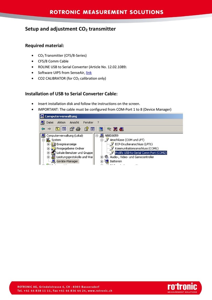
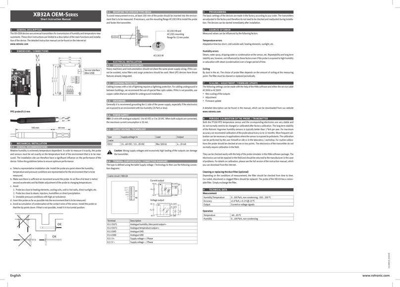
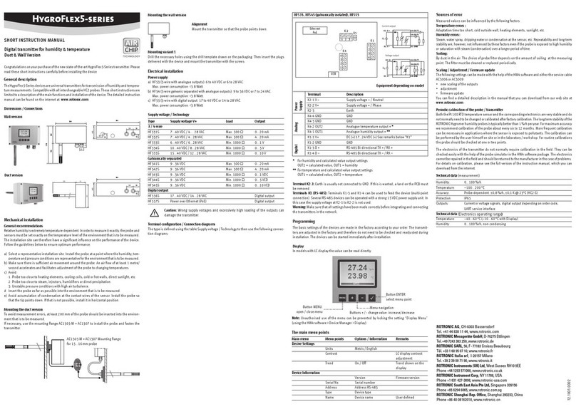
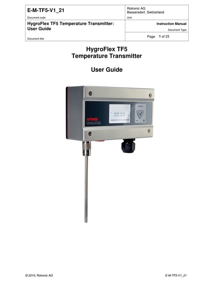
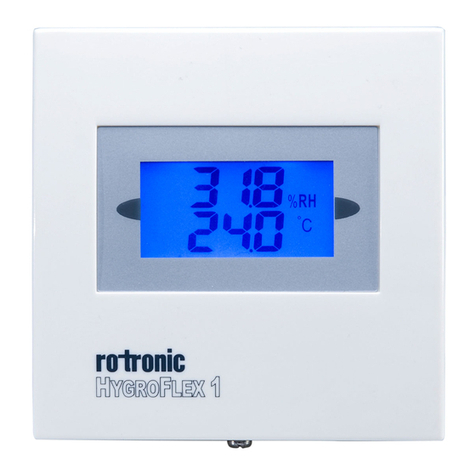
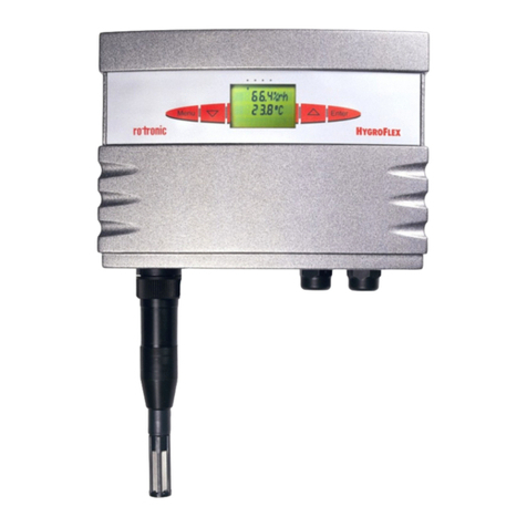
Rotronic HygroFlex 1 User manual

HygroFlex
Humidity Temperature Transmitter
Instruction Manual
V 3.1

- 2 -
E_IMHygroFlex_V3.1.doc
Contents
Overview...............................................................................................................................................3
General Description..............................................................................................................................4
Power Requirements ........................................................................................................................4
Probes and Probe Inputs..................................................................................................................5
Analogue Outputs (HygroFlex 1 and HygroFlex 3) ..........................................................................7
Connection to a PC - RS232 Digital Port .........................................................................................8
HW3 Software ..................................................................................................................................8
RS485 Networking (HygroFlex 2 and HygroFlex 3) .........................................................................8
Unit System ......................................................................................................................................8
Optional Display and Keypad ...........................................................................................................9
Keypad..............................................................................................................................................9
Installation ..........................................................................................................................................10
Installation of the Transmitter Enclosure ........................................................................................10
Front cover removal........................................................................................................................10
Re-attaching the ribbon cable (cover with optional Display and Keypad)......................................11
Configuration of the Analogue Outputs ..........................................................................................16
Electrical Installation Guidelines.....................................................................................................17
Serial Network Configuration (HygroFlex 2 and HygroFlex 3 only)................................................17
HygroFlex Function Menu ..................................................................................................................19
CALCULATE (HygroFlex 2 and HygroFlex 3) ................................................................................19
DISPLAY (HygroFlex 2 and HygroFlex 3 with optional LC display)...............................................20
ADJUST M.PT (2- to 4-point adjustment against a reference environment)..................................20
ADJUST 1PT (1-point adjustment against a reference environment)............................................22
ADJUST REF (1-point adjustment against a reference probe) ......................................................23
PROBE ...........................................................................................................................................23
SETTINGS......................................................................................................................................24
SYS Status .....................................................................................................................................24
OUTPUT.........................................................................................................................................24
Errors and Status Messages ..........................................................................................................25
Test Connector for the HygroPalm Indicator......................................................................................26
Display the Probe Measurements ..................................................................................................26
Functions (except ADJUST M.PT and ADJUST 1PT)....................................................................27
Functions ADJUST M.PT and ADJUST 1PT..................................................................................27
Function ADJUST REF...................................................................................................................27
Environmental Limits ..........................................................................................................................28
Maintenance .......................................................................................................................................28
On-Site Maintenance......................................................................................................................28
Factory / Metrology Lab. Maintenance ...........................................................................................28
Specifications .....................................................................................................................................29
Appendix 3: Maintenance of the ROTRONIC probes ........................................................................32
Cleaning or Replacing the Dust Filter of the Probe........................................................................32
Periodic Calibration Check of the Probes.......................................................................................32
Appendix 4: Calibration Basics...........................................................................................................33
Temperature Calibration.................................................................................................................33
Humidity Calibration .......................................................................................................................33
Appendix 5: Humidity Definitions........................................................................................................35
Appendix 6: Dew Point Accuracy .......................................................................................................37
Appendix 7: RS232 Communication Protocol ....................................................................................38
Appendix 9: Accessories for the HygroFlex .......................................................................................42
Appendix 10: Electrical Installation Guidelines...................................................................................43
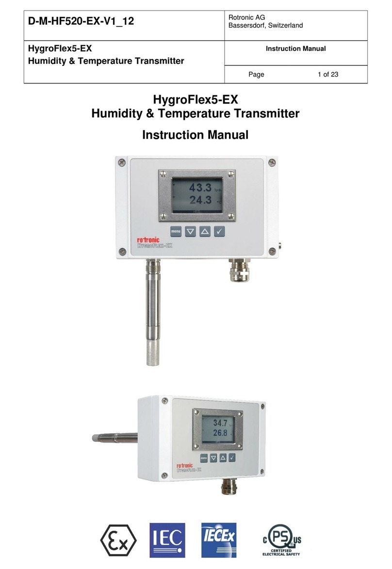
- 3 -
E_IMHygroFlex_V3.1.doc
About the version number: this manual is valid for all instruments that display version
number 3.x, where 3.x can be 3.0, 3.1, etc. (see Function Menu, SYS STATUS).Changes in the
last digit of the version number reflect minor changes in the internal software of the
instrument that do not affect the manner in which the instrument should be operated.
Note: functions such as instrument configuration with a PC as well as the calibration of
HygroClip probes with a PC require the optional HW3 software. Instructions for using the
HW3 software are not included in this manual. These instructions are shipped separately on
the same CD ROM as the HW3 software.
Overview
The HygroFlex is a series of 3-wire humidity temperature transmitters that is available with a wide
variety of probes for use in many different industrial and scientific applications. The HygroFlex
series uses a micro-processor based design to achieve unparalleled accuracy, reliability and
versatility.
The HygroFlex is available in 3 different models:
HygroFlex 1: basic industrial transmitter with analogue outputs
relative humidity and temperature
-compatible with any ROTRONIC HygroClip digital probe 1)
-relative humidity and temperature analogue outputs
-test connector for communication with the HygroPalm indicator 2)
-software-based calibration (HygroClip probes only)
-internal service connector (RS232) for configuration with PC (units, ranges)
-two linearized analogue outputs, signal type (mA, V) configurable by means of jumpers 3)
-optional LC display and keypad 4)
1) ROTRONIC analogue probes are also accepted with some restrictions
2) allows the HygroPalm to read the transmitter or to calibrate a digital probe
3) 0..1V, 0..5V, 0..10V, 0..20 mA, 4..20 mA
4) allows direct calibration of digital probes by the transmitter and direct access to other functions
HygroFlex 2: fully digital, networkable industrial transmitter
relative humidity, dew point (or other) and temperature
-compatible with any ROTRONIC HygroClip digital probe 1)
-optional analogue input for second probe 2)
-relative humidity, temperature, dew point, wet bulb, mixing ratio, enthalpy, etc 3)
-test connector for communication with the HygroPalm indicator 4)
-software-based calibration (HygroClip probes only)
-RS232 and RS485 digital ports 5)
-optional LC display and keypad 6)
1) ROTRONIC analogue probes are also accepted with some restrictions
2) pressure probe or ROTRONIC HygroClip digital probe – some restrictions apply
3) uses either a fixed barometric pressure value or the measurements from an analogue pressure probe
for those parameters that require pressure as a computational input. The fixed pressure value can be
changed with the optional HW3 software.
4) allows the HygroPalm to read the transmitter or to calibrate a digital probe
5) The computed parameter (dew point or other) is not sent to these ports. Use of the HW3 software on
a PC allows real time computation of the dew point (or other) and facilitates both networking and
instrument configuration
6) allows direct calibration of digital probes by the transmitter and direct access to other functions

- 4 -
E_IMHygroFlex_V3.1.doc
HygroFlex 3: analogue / digital, networkable industrial transmitter
relative humidity, dew point (or other) and temperature
-compatible with any ROTRONIC HygroClip digital probe 1)
-optional input for second probe 2)
-relative humidity, temperature, dew point, wet bulb, mixing ratio, enthalpy, etc 3)
-test connector for communication with the HygroPalm indicator 4)
-software-based calibration (HygroClip probes only)
-RS232 and RS485 digital ports 5)
-three linearized analogue outputs, signal type (mA, V) configurable by means of jumpers 6)
-optional LC display and keypad 7)
1) ROTRONIC analogue probes are also accepted with some restrictions
2) pressure probe or ROTRONIC HygroClip digital probe – some restrictions apply
3) Uses either a fixed barometric pressure value or the measurements from an analogue pressure probe
for those parameters that require pressure as a computational input. The fixed pressure value can be
changed with the optional HW3 software.
4) allows the HygroPalm to read the transmitter or to calibrate a digital probe
5) The computed parameter (dew point or other) is not sent to these ports. Use of the HW3 software on
a PC allows real time computation of the dew point (or other) and facilitates both networking and
instrument configuration
6) 0..1V, 0..5V, 0..10V, 0..20 mA, 4..20 mA - corresponding to relative humidity, temperature and
computed parameter (or relative humidity of second probe)
7) allows direct calibration of digital probes by the transmitter and direct access to other functions
General Description
Power Requirements
The HygroFlex is available with a choice of two basic internal power modules:
-standard power module for operation with 12 to 35 VDC (maximum 300 mA) or with 12 to 24 VAC.
-optional power module for operation with voltages within the range of 90 to 264 VAC (50/60 Hz).
HygroFlex 1 HygroFlex 2 HygroFlex 3

- 5 -
E_IMHygroFlex_V3.1.doc
Probes and Probe Inputs
Model HygroFlex 1 HygroFlex 2 HygroFlex 3
number of probe inputs 1 1 (standard) or 2 (optional)
probe types (see below) ROTRONIC Digital
ROTRONIC
Analogue
ROTRONIC Digital
ROTRONIC Analogue
Third-Party Analogue
number of digital input channels 1 1 (input 1) + 1 (input 2 - optional)
number of analogue input channels 2 2 (input 1) + 1 (input 2 - optional)
analogue input A/D resolution 10-bit 10-bit
Unless otherwise specified when ordering, all probe inputs are factory programmed to accept a HygroClip
digital probe. Prior to using any analogue probe, the corresponding input should be re-programmed. This can
be done with the HW3 software after connecting the RS232 port to a PC (see separate HW3 manual). A
matching adapter cable is required to connect analogue probes.
HygroClip Digital Probes
The HygroFlex is primarily designed for use with the ROTRONIC HygroClip digital humidity
temperature probes. These probes permit to take full advantage of all the features and functions of
the HygroFlex such as the software based calibration.
The ROTRONIC HygroClip digital probes are highly accurate and are calibrated entirely by means
of software (no adjustment potentiometers). Because calibration and other data are stored in the
probe non-volatile memory, the probes are fully interchangeable. When a probe requires calibration
or has to be repaired, it can be replaced with another probe in a few seconds. The ROTRONIC
HygroClip digital probes are available in different configurations so as to meet the requirements of
each application:
HygroClip IW
for surface mount (area monitoring)
max. 85°C (185°F) – wire mesh filter
observe temperature limits of transmitter
electronics
HygroClip IC-1 (100mm) / IC-3 (250mm)
for through-wall installation
max. 200°C (392°F) - wire mesh filter
HygroClip IM-1 (120mm) / IM-3 (270mm)
for through-wall installation in high humidity
applications
max. 200°C (392°F) - wire mesh filter
HygroClip IE-1 (G ½”) / IE-2 (NPT ½”)
for compressed air (max. 50 bar / 725 PSI)
max. 85°C (185°F) – sintered steel filter
to avoid errors, temperature should be the
same on both sides of the mounting wall
HygroClip IC-05
for measurement in tight spaces
max. 100°C (212°F)

- 6 -
E_IMHygroFlex_V3.1.doc
Analogue Probes
Depending on the model and options, the HygroFlex transmitters can be used with one or two
analogue probes. Both the scale and unit of the analogue input signals can be defined with the HW3
software. For example, an analogue pressure probe may used to provide the local value of
barometric pressure for the computation of parameters such as the wet bulb temperature, mixing
ratio or enthalpy.
Use of analogue probes is subject to the following restrictions and limitations:
a) ROTRONIC analogue humidity-temperature probes with the standard temperature output signal
of – 0.5…2.0 V = -50…200°C: because the HygroFlex cannot read a negative voltage signal,
temperature measurement is generally limited to values above freezing.
b) Third-party analogue probes: single channel probes (one signal), output signal within the range
of 0 to 2.5 VDC, supply voltage: 15 VDC or less, maximum current consumption: 10 mA.
c) Resolution is limited by the 10-bit A/D converter used for the analogue inputs. This converter
provides a theoretical maximum of 1024 counts for an input voltage span of 2.5 VDC. In theory,
this gives a resolution of 2.5 / 1024 = 0.00244 V. In practice, it is not possible to get 100% of the
counts from an A/D converter and the actual resolution should be about 0.0027 V (typical). For
Probe Extension Cable AC1616/xxx
with built-in signal booster
xxx = 002 to 200
from 2 to 200 m (about 6.5ft to 656ft)
max. temperature 85°C (185°F)
HygroClip ID-EX-xxx (intrinsically safe)
for through-wall installation
xxx = 002 to 100
from 2 to 100 m cable length (about 6.5ft to 328ft)
max. temperature at sensors: 200°C (392°F)
probe length 250 mm - sintered steel filter
HygroClip IW-EX-xxx (intrinsically safe)
for surface mount (area monitoring)
xxx = 002 to 100
from 2 to 100 m cable length (about 6.5ft to 328ft)
max. temperature 40°C (104°F)
probe length 150mm
sintered steel filter
ZB1 Zenner Barrier for ID-EX and IW-EX
AC1617xxx Connecting Cable for ZB1
with built-in signal booster
xxx = 002 to 100
2 to 100m
(
about 6.5ft to 328ft
)

- 7 -
E_IMHygroFlex_V3.1.doc
example, if a probe with a temperature signal of 0..1 V = 0…100°C is being used, the signal
resolution will be about 100 x 1 x 0.0027 = 0.27°C
Analogue Outputs (HygroFlex 1 and HygroFlex 3)
Model HygroFlex 1 HygroFlex 2 HygroFlex 3
analogue outputs - relative humidity
- temperature
N/A
(digital output only)
Any three of:
- relative humidity
- temperature
- computed parameter
- user defined calculation
see note1) below
output signals 2)
configurable with
jumpers
0…1 V
0…5 V
0…10 V
0…20 mA
4…20 mA
N/A
0…1 V
0…5 V
0…10 V
0…20 mA
4…20 mA
D/A output
resolution
humidity: 12-bit
temperature: 16-bit N/A
Out 1: 12-bit
Out 2: 16-bit
Out 3: 12-bit
options
floating analogue
current outputs
(galvanic separation)
N/A
floating analogue current
outputs
16-bit D/A resolution for
Out1 allows 0.1
resolution with a span of
more than 200 units.
1) Any of the 3 analogue outputs of the HygroFlex 3 can be set to correspond to humidity
[probe 1 or 2] or temperature [probe 1 or 2] or calculated parameter [probe 1 or 2] or user
defined calculation or optional analogue probe signal (such as pressure). The HygroFlex is
set at the factory as specified when ordering. These settings can be changed at any time
with the optional HW3 software.
2) The output signals are set at the factory according to the type and range specified when ordering. A
label located on the transmitter housing shows the type of output signal for each unit.
The analogue output signals are linear and are consistent with the requirements of most data/signal
processing instrumentation (panel meter, controller, computer card, etc.).

- 8 -
E_IMHygroFlex_V3.1.doc
Connection to a PC - RS232 Digital Port
The HygroFlex 1 has an internal RS232 service connector. Both the HygroFlex 2 and 3 have an
external RS232 connector (located on the connector plate). In principle, any communication
software can be used to interrogate and read the HygroFlex with the commands described in
appendix 7 (RS232 communication protocol). Use of the optional HW3 software simplifies this task.
It is important to note the following:
HygroFlex 1: use of the RS232 port (internal service connector) is limited to configuring the
instrument (units, range, etc.). Measurement data and calibration functions are not available on this
port.
HygroFlex 2 and 3: use the RS232 port to configure the transmitter, calibrate the probe and connect
the transmitter to a network. The computed parameter (dew point or other) is not part of the digital
communication (limited to %RH and temperature – in the unit selected for the transmitter).
HW3 Software
The HW3 software (optional) allows real time computation of the dew point (or other) by the PC
while providing additional functionality such as:
-RS485 networking (up to 32 units)
-full access to instrument configuration (unit system, etc.)
-calibration of the ROTRONIC HygroClip digital probes with or without HygroFlex
-data logging to a PC disk file
-graphic functions (both on and off-line)
HW3 runs on any PC with Windows 98 or NT. For more details see separate instruction manual
provided with the HW3 software.
RS485 Networking (HygroFlex 2 and HygroFlex 3)
With the optional HW3 software up to 32 HygroFlex 2 or 3 transmitters can be connected together
on a network. Any transmitter can be used either as a slave or a master, without special
configuration. Each unit must be given a unique network address with the HW3 software (0 to 31).
The master is automatically the unit that is connected to the COM port of the PC by means of the
RS232 port. See Electrical Installation for details.
Unit System
The unit system of the HygroFlex (Metric or English) is factory programmed as specified when the
instrument was ordered. The unit system can be easily be changed by the user with the optional
HW3 software.
RS232: 3 wires (including ground wire)
RS485: 2 wires
PC
(
HW3
)
CO
M P
o
r
t
Unit 0 Unit 1 Unit 31
RS232
RS485
RS485
RS485
RS232 RS232
RS232 up to 150m (490 ft) RS485 up to 1000m (3300 ft)

- 9 -
E_IMHygroFlex_V3.1.doc
Optional Display and Keypad
The LC display shows which probe input is being displayed (small indicator on top of the display)
and up to 2 parameters measured by the probe, with the associated engineering unit. When
relevant, the message line provides additional information.
SS
Keypad
Humidity and Temperature
Calculated Value and Temperature
Calculated Value and Humidity
MENU :Press this key to activate the function menu. The different
menu items appear on the LCD message line. Press this key again
to exit the menu
UP / DOWN: Press one of these keys to select the probe input
for the display and functions. When the function menu is active,
use these keys to navigate the menu, make a selection or to
change a number on the display.
ENTER: When the menu is active, press
this key to confirm a selection.
Probe Input Indicator
(1-2) from left to right
Engineering
Units
Message Line
Parameter or
Trend Indicators
8.8:8.8
8.8:8.8
To prevent unauthorized or accidental changes, access from
the keypad to the calibration functions can be blocked out
when configuring the HygroFlex with HW3. This also
prevents access to the calibration functions with the
HygroPalm calibrator.

- 10 -
E_IMHygroFlex_V3.1.doc
Installation
Each HygroFlex transmitter is shipped in an individual box, separately from the probe. The shipping
box has a label with the following information: instrument type, main specifications and serial
number. An identical label is located inside of the transmitter enclosure.
Installation of the Transmitter Enclosure
Note: see appendix 8 for the optional metal enclosure
The HygroFlex is comprised of 5 parts: mounting bracket (1), electronics housing (2), main circuit
board (3), connector plate (4) and front cover with or without optional display and keypad (5).
To attach the transmitter to a mounting surface:
1) Attach the wall plate in the position shown above to an appropriate surface using 4 screws.
2) Slide the electronics housing down on the wall plate to the mechanical stop
Front cover removal
1
2
3
4 5
V-shaped
slot
After unpacking the
HygroFlex, separate the
mounting bracket from the
back of the housing.

- 11 -
E_IMHygroFlex_V3.1.doc
The front cover is held in place by 4 small tabs molded into the electronics housing. To remove the
cover, insert a screwdriver in the V-shaped slot on top of cover and press lightly to unlock prior to
pulling the cover away from the electronics housing.
Note: If the cover has the optional display and keypad, it is connected to the main circuit board by a
ribbon cable. When removing the front cover, this cable can easily become detached. This is
nothing to worry about since the cable can be just as easily re-attached.
Front Cover Installation
To put the front cover back on the HygroFlex, proceed as shown below:
Re-attaching the ribbon cable (cover with optional Display and Keypad)

- 12 -
E_IMHygroFlex_V3.1.doc
Zero-insertion-force connectors are used for the ribbon cable that connects the cover and the main
printed circuit board.
To re-attach the ribbon cable, unlock the connector (see above) and slide the cable back into the
connector as indicated below. Lock the connector in place and verify the cable is firmly held in
place.
Each end of the ribbon cable has a contact side and a blue insulated side. When inserting the cable
in the connector, position the contact side of the flat ribbon cable as indicated below.
Note: disconnecting and reconnecting the ribbon cable while the transmitter is powered may cause
the display to remain blank. In that case, un-power and power again the transmitter.
ribbon cable (can be pulled out)
zero-insertion-force connector
to unlock: grab both sides of
outer frame up and pull up
to lock: push down outer frame
printed circuit board
outer frame

- 13 -
E_IMHygroFlex_V3.1.doc
PCB Connectors
All terminal blocks are of the plug-in type so that the connector
plate can be pulled out if required.
Cable grips (5 and 6)provide effective sealing only with cables
having the proper outside diameter. Preferably, use a cable with
an outside diameter of 6 to 7 mm (0.236 to 0.275”) and with
18AWG wires. Seal any unused cable grip. On request, the
connector plate is available with 1/2” conduit adapters instead of
cable grips.
Ground the HygroFlex, especially if the electronics will be
subjected to a low humidity environment (35 %RH or less). We
also recommend running the analogue output signal cable
separately from the power cable.
Note that all input / output signal grounds - analog and digital - are
tied together.
Starting with PCB version 66.0738.0402, there is no connection
between signal ground and terminal 3 of the power terminal block
TB1. If so desired, a connection can be established by closing
solder pad B18, next to TB1. On previous versions of the PCB, the
signal ground and terminal 3 of TB1 are always tied together.
1- Main Probe Input (J2)
1 : Temperature (analogue+)
2 : Humidity (analogueue +)
3 : GND
4 : Digital Input Output
5: +VDC
2- Test (J4)
(for HygroPalm Calibrator)
1 : GND
2 : Digital Input Output
3- Optional 2nd Probe Input (J3)
(except HygroFlex 1)
1 : Analogue Input Signal (+)
2: GND
3 : Digital Input Output
4 : +15 VDC ±0.5 VDC
4- RS232/RS485 (J5)
(except HygroFlex 1)
1 : RI – (485)
2 : RI + (485)
3 : GND
4 : RX
5 : TX
5 - Analogue Outputs (K2/ TB2)
(except HygroFlex 2)
1 : Out 1 (+)
2 : Out 2 (+)
3 : Out 3 (+) – HygroFlex 3 only
4 : GND (common)
6- Power (K1/TB1)
(check label inside enclosure)
1 : AC N or DC –
2 : AC Ph or DC +
3 : GND (see note below)
MTA :
service / configuration connector
connect to PC with cable AC1623

- 14 -
E_IMHygroFlex_V3.1.doc
Connector Pin-Out Diagrams
Note: the contact side of the female connector is the same as the solder side of the matching male connector.
Probe 1
–
TUCHEL T7 (7-pin female shown from contact side)
Pin # Function Pin# on PCB connector J2
E GND 3
1 Temperature – analogue (+) 1
3 DIO (digital) 4
5 + VDC (15 VDC±0.5 VDC) 5
6 Humidity – analogue (+) 2
Test Connector (2-pin female shown from contact side)
Pin # Function Pin# on PCB connector J4
1 DIO (digital) 2
2 GND 1
Probe 2 (5-pin female shown from contact side)
–
optional
Pin # Function Pin# on PCB connector J3
2 + VDC(15 VDC±0.5 VDC) 4
3 GND 2
4 DIO (digital) 3
5 Analogue (+) 1
RS232 / RS485 (5-pin female shown from contact side)
Pin # Function Pin# on PCB connector J5
1 TXD 5
2 RXD 4
3 GND 3
4 RI + 2
5 RI - 1
Analog Outputs (4-pin female shown from contact side)
–
optional
Pin # Function Pin# on PCB connector
1 Output 1 (+) 1
2 Output 2 (+) 2
3 Output 3 (+) 3
4 GND 4
RS232 connection (DB9 female connecting to a PC or terminal serve
r
)
Pin # Function
2 RX
3 TX
5 GND

- 15 -
E_IMHygroFlex_V3.1.doc
Electrical Diagrams (analogue outputs)
Before making the electrical connections, be sure to correctly identify each connector and terminal.
Applying power to any of the input or output terminals can severely damage the transmitter.
12 to 35 VDC or 12 to 24 VAC supply voltage and voltage output signals
TB1 (2) 12…35 VDC (+) or 12…24 VAC neutral TB2 (1) Relative humidity (+)
TB1 (1) 12…35 VDC (-) or 12…24 VAC Ph TB2 (2) Temperature (+)
TB1 (3) Ground TB2 (3) Calculated Parameter (+)
TB2 (4) Common (-)
90…264 VAC with optional power module and current output signals
TB1 (2) 90…264 VAC Neutral TB2 (1) Relative humidity (+)
TB1 (1) Phase TB2 (2) Temperature (+)
TB1 (3) Ground TB2 (3) Calculated Parameter (+)
TB2 (4) Common (-)
RL1)RL1)
RL1
)
1) minimum load:
1000 ohm
~
~
TB1 TB2
2
1
3
1
2
3
4
~
RL1)RL1)
RL1)
1) maximum load :
500 ohm
wiring included.
~
~
TB1 TB2
2
1
1
3
2
3
4
~
B18
Solder
p
ad B18: see bottom of
p
a
g
e 13
Solder
p
ad B18: see bottom of
p
a
g
e 13
B18

- 16 -
E_IMHygroFlex_V3.1.doc
Floating Current Outputs (option)
Configuration of the Analogue Outputs
On the HygroFlex 1 and HygroFlex 3, the type of output signal can be selected by means of two
jumpers for each output. These jumpers are located on the PCB of electronics module:
Signal OUT31) OUT2 OUT1
0…1 V B2, B3, B31 B12, B13, B31 B22, B23, B31
0…5 V B2, B4, B32 B12, B14, B32 B22, B24, B32
0…10 V B2, B5, B31, B32 B12, B15, B31, B32 B22, B25, B31, B32
0…20mA B1, B3, B33, B34 B11, B13, B33, B34 B21, B23, B33, B34
4…20mA B1, B3, B31, B33, B34 B11, B13, B31, B33, B34 B21, B23, B31, B33, B34
1) HygroFlex 3 only
The scale (or range) of each analogue output can be changed with the HW3 software (see separate
instructions). On the HygroFlex 3, the parameter corresponding to the third output can also be
changed with the HW3 software (see separate instructions).
Before making the electrical connections, be sure to correctly identify each connector and terminal.
Applying power to any of the input or output terminals can severely damage the transmitter.
RL1)
RL1)
RL1)
B31
B32
B33
Res.
RS232 / RS485
HygroFlex 1: to configure the temperature range
and unit, use this 3-pin service connector and
connect to a PC with cable # AC1623.
HygroFlex 3: the transmitter can be configured
by connecting the RS232 / RS485 output to a
PC.
For both transmitters, configuration requires the
HW3 software installed on the PC.
B34
Solder pad B18: see bottom of page 13
1) maximum load : 500 ohm, wiring included
B18

- 17 -
E_IMHygroFlex_V3.1.doc
Electrical Installation Guidelines
Please see Appendix 10 for general guidelines regarding the electrical installation of this product.
Serial Network Configuration (HygroFlex 2 and HygroFlex 3 only)
Serial Network
The RS232 connection between the HygroFlex and a PC requires 3 wires: RX, TX and GND 1).
Without a signal booster, the maximum cable length is limited to 150 m (490 ft). The RS485
connection requires two wires and should not exceed a total of 1,000m / 3,300 ft.
1) See bottom of page 13
Each HygroFlex 2 or 3 is supplied with a 2-cable, 5-pin connector (see Connector Diagrams). On
the first unit of a serial network, both the RS232 and RS485 wiring share this connector. Be sure to
observe the polarity for each connection. Wall mounted RJ45 receptacles are a convenient means
of connecting additional units to the RS-485 cable.
Please see also Appendix 10 for additional guidelines regarding the RS-485 wiring installation.
PC
COM
RS232 (3 wires)
maximum 150 m (490 ft)
RS485 (2 wires)
maximum 1,000 m (3,300 ft)
RJ45
2 wires
2-cable
connector
Unit 0 Unit 1 Unit 2 Unit 31
Prior to networking the transmitters, they should be individually configured with the HW3
software (see separate instructions on the HW3 CD ROM). Proceed as follows:
1) Connect each transmitter, one at a time, to the COM port of the PC
(see also note below)
2) Assign to each transmitter a unique network address (a number between 0
and 31). By default, all transmitters are shipped by the factory with address 0.
Note: if you assign address 1 to the first transmitter, you can connect a second
transmitter (with the 0 default address) to the network and then use the network to
directly change its address from 0 to 2. Proceed in this manner to add more
transmitters one at a time, using addresses 3, 4, 5, etc.
3) For easier identification, you may also want to give at that time a descriptive name
(maximum 30 characters) to each transmitter.

- 18 -
E_IMHygroFlex_V3.1.doc
Probe Installation Guidelines
Connect the probe to probe input 1 (main probe input). Except for probe model IW (area
monitoring), probes are connected to the HygroFlex by means of a cable (attached to the probe).
Do not remove the dust filter or slotted cap from the probe. Both sensors can easily be damaged
when not protected.
For best results, please observe the following guidelines:
-Install the probe at a location where humidity, temperature and pressure conditions are
representative of the environment or process to be measured. Avoid the following: (a) Close
proximity of the probe to a heating element, a cooling coil, a cold or hot wall, direct exposure to
sun rays, etc. (b) Close proximity of the probe to a steam injector, humidifier, direct exposure to
precipitation, etc. (c) Unstable pressure conditions resulting from excessive air turbulence.
-If possible, choose a location that provides good air movement at the probe: air velocity of at
least 1 meter/second (200 ft/ minute) facilitates adaptation of the probe to changing temperature.
-When installing the probe through a wall, immerse as much of the probe as possible in the
environment to be measured.
OK
NG NG
Small Diameter Duct
Short Probe
OK NG
9 to 9.5" immersion
Position the probe so as to prevent the accumulation of condensation water at the level of the
sensor leads. Install the probe so that the probe tip is looking downward. If this is not possible,
install the probe horizontally.
Depending on the probe model, a probe holder (mounting flange with a compression fitting) can
facilitate installation through a wall.
Future maintenance can be made easier by providing next to the probe a calibration access orifice.
During maintenance, this permits the insertion of a reference probe (calibrator).The calibration
access orifice should have the same size as the orifice used to install the probe and can be
equipped with a probe holder.

- 19 -
E_IMHygroFlex_V3.1.doc
HygroFlex Function Menu
The functions of the HygroFlex can be accessed either with the optional display and keypad or by
connecting a HygroPalm indicator to the Test connector of the HygroFlex (see Remote Mode).
Some functions, including all calibration functions, can also be accessed with the HW3 software.
To access the function menu from the HygroFlex keypad, press the MENU key. The first menu item
appears on the message line of the LC display. Use the UP or the DOWN key to navigate the menu.
When the desired menu item appears on the message line of the LC display, press the ENTER key
to select. Some menu items have sub-items. These can be selected with the UP, DOWN and
ENTER keys. To exit the menu and return to the normal display mode, press the MENU key. The
instrument also returns automatically to the normal display mode when no key is being pressed for
some time (main menu: 10 sec., submenu: 30 sec.).
CALCULATE (HygroFlex 2 and HygroFlex 3)
Definition
This function is used to select the humidity parameter that is calculated and displayed by the
instrument 1) . Any selection made here has no effect on analogue output #3 (computed parameter)
of the HygroFlex 3. Use the HW3 software to change the computed parameter sent this output.
1) does not apply to third-party analogue probes.
The calculated parameter is selected individually for each probe connected to the instrument 1).
Prior to entering this function, select on the display the probe input to programmed.
The unit system (Metric or English) is factory programmed according to what was specified when
the instrument was ordered. The unit system can be selected with the optional HW3 software (see
separate instructions).
Selections
Parameter M E HygroFlex 1 HygroFlex 2 HygroFlex 3
Dew Point / Frost Point 1) °C °F N/A x x
Wet Bulb Temperature °C °F N/A x x
Enthalpy J/g BTU/lb N/A
x x
Vapour Concentration g/m3gr/cuft N/A x x
Specific Humidity g/kg gr/lb N/A x x
Mixing Ratio g/kg gr/lb N/A x x
Vapour Concentration
at Saturation
g/m3gr/cuft N/A x x
Partial Pressure
of Water Vapor
hPa PSI
In Hg
N/A x x
Saturation Pressure
of Water Vapor
hPa PSI
In Hg
N/A x x
Pressure Constant 2)
(Barometric Pressure)
hPa PSI
In Hg
N/A x x
1) The standard factory setting is frost point for values below freezing. This setting can be changed
to dew point with the optional HW3 software
2) This selection shows the fixed value that is used for computing the parameters that require
barometric pressure as an input. The fixed pressure value can be changed with the optional HW3
software. Both the HygroFlex 2 and HygroFlex 3 can also be programmed to accept the input from a
pressure probe (variable pressure value).

- 20 -
E_IMHygroFlex_V3.1.doc
DISPLAY (HygroFlex 2 and HygroFlex 3 with optional LC display)
Definition
This function is used to select which parameters are displayed by the instrument. The display mode
is specified globally for all humidity probes connected to the instrument.
HygroFlex 3: the display selection has no effect on the analogue outputs.
Selections
-Measurement
Relative humidity and temperature or the parameter measured by any third party probe
connected to the instrument.
-Calculated + Temperature
Calculated parameter (as selected under CALCULATE) and temperature. This selection is not
available with third-party probes.
-Calculated + Humidity
Calculated parameter (as selected under CALCULATE) and relative humidity. This selection is
not available with third-party probes.
-User Calc
User defined calculation such as the difference between temperature and dew point of any
probe. The display shows only the calculated value. See the separate HW3 manual for
instructions on how to program the HygroFlex 2 or 3 to compute a user specified parameter.
ADJUST M.PT (2- to 4-point adjustment against a reference environment)
Definition
The Adjust M.PT function permits to calibrate and adjust a ROTRONIC HygroClip digital probe
against a known reference environment. This function is designed to permit calibration at 2
temperature values and at up to 4 relative humidity values.
Selections
The Adjust M.PT function offers the following selections:
RHS: Humidity calibration using the ROTRONIC Humidity Standards 1)
Humidity: Humidity calibration using any suitable reference environment
Temperature: Temperature calibration using any suitable reference environment
1) For humidity calibration, ROTRONIC offers convenient, certified humidity standards to generate known
humidity values (for more details, see Appendix 3 - Humidity Calibration).
Other manuals for HygroFlex 1
1
This manual suits for next models
2
Table of contents
Other Rotronic Transmitter manuals

Rotronic
Rotronic HygroClip IC-1-EX User manual

Rotronic
Rotronic CF5-D User manual

Rotronic
Rotronic HygroFlex 5 Series User manual

Rotronic
Rotronic HygroFlex User manual

Rotronic
Rotronic HygroFlex HF3 Series User manual

Rotronic
Rotronic XB32A OEM Series User manual

Rotronic
Rotronic HygroFlex5-EX User manual

Rotronic
Rotronic XB User manual

Rotronic
Rotronic HygroFlex 1 User manual

Rotronic
Rotronic PF4 User manual