Sofraser 9200 User manual

Original version
REF.: 380-5
9
200
Viscosity and temperature
transmitter
Technical Manual


Technical Manual 9200
REF: 380/5 3
IMPORTANT
THE OFFSET ADJUSTMENT IN THE AIR
MUST BE THE FIRST TASK COMPLETED.
Offset adjustment procedure is detailed in § 3.3.
1. CLEAN AND DRY THE SENSOR ROD.
2. BE SURE THE PROCESS IS EMPTY. THE ROD MUST BE VIBRATING IN THE AIR.
3. INSTALL THE SENSOR ON THE PROCESS AND FIX IT WITH ITS 4 SCREWS.
4. POWER ON THE DEVICE, WAIT 15 MINUTES.
5. PRESS THE “HOME” BUTTON UNTIL REACHING THE OFFSET MENU AND PRESS
“OK”.
6. FOLLOW THE INSTRUCTIONS DISPLAYED ON THE ELECTRONICS SCREEN.
7. PRESS “OK” TO ADJUST THE OFFSET. IT MEANS THE RAW SIGNAL IS SHIFTED TO
THE VOLTAGE REFERENCE DEFINED IN THE FACTORY CALIBRATION STAGE.
THE NEW OFFSET VALUE IS THEN DISPLAYED.

Technical Manual 9200
REF: 380/5 4
Table of contents
1. TRANSMITTER PRINCIPLE ................................................................................................. 5
2. PROCESSOR TECHNICAL CHARACTERISTICS .................................................................. 6
2.1 Electronic device size ............................................................................................................................................ 6
2.2 Main features .............................................................................................................................................................. 7
2.2.1
Best performance conditions .................................................................................................. 7
2.2.2
Display ..................................................................................................................................................... 7
2.3 Connections ................................................................................................................................................................ 7
2.3.1
Top connector .................................................................................................................................... 8
2.3.2
Bottom connector ........................................................................................................................... 9
3. THE 9200 OPERATING FUNCTIONS ................................................................................ 10
3.1 Start and menus ..................................................................................................................................................... 10
3.2 Raw values .................................................................................................................................................................... 11
3.3 Offset ................................................................................................................................................................................ 11
3.4 Viscosity and temperature units .................................................................................................................. 12
3.5 Check 4-20 mA ......................................................................................................................................................... 12
3.6 Correlation ................................................................................................................................................................... 13
3.7 Enable or disable temperature ..................................................................................................................... 14
4. RS485 FRAME PROTOCOL ............................................................................................... 15
5. SOFRASER INTERFACE SOFTWARE ................................................................................ 17
5.1 The main features ................................................................................................................................................... 17
5.2 The user-friendly interface ................................................................................................................................ 17
6. TROUBLESHOOTING ........................................................................................................ 18

Technical Manual 9200
REF: 380/5 5
1. Transmitter principle
The measuring chain is composed of three inseparable elements: the sensor, its cable and the 9200
transducer that controls it. The sensor cannot be used with another transducer or another
cable type or length because they are all a part of the resonant loop so they are matched
together as one vibrating system.
The active part of the sensor is composed of a vibrating rod held in oscillation at resonance frequency
by driving magnets. When the rod is immersed into a viscous material, the amplitude of the
vibration is dampened. The vibration amplitude varies according to the product viscosity
where the rod is immersed.
The sensor receiving coil detects the response and the signal is converted to a viscosity value
through the electronic device. The factory calibration is performed with standard oils.
The transducer acquires the coils’ amplitudes and frequency and generates various signals. These
signals represent the properties being measured. It is also in charge of powering the whole
system. It gives viscosity and temperature information through the serial communication and
displays it. The transmitter also allows simple settings as the very important “zero in the air”
procedure.

Technical Manual 9200
REF: 380/5 6
2. Processor technical characteristics
2.1 Electronic device size
The electronic box has the purpose to be fitted in a panel, close to the process line. The collar is the
only visible part, composed of a face plate and a LCD screen. It is continuously displaying the
viscosity value and, in the case there is a Pt100 probe, the temperature value.
The ID label is stick on the bottom of the box. Main information is written down. There is also another
sticker on the back panel to remind how to connect the sensor, the outputs and the power
supply (see §2.3).
It has an IP20 rating. Its weight is about 240 g.
Hereunder are the different views and the associated dimensions (in mm) of the device.
Collar (visible part): 48 * 96 * 10
Fitted part: 43 * 90 * 115
Panel cut out: 44 * 91
43 mm
115 mm
96 mm
Left side
96 mm
48 mm
124 mm
Front panel

Technical Manual 9200
REF: 380/5 7
2.2 Main features
2.2.1
Best performance conditions
The processor must be connected to a 24 VDC (± 2.4 V) stabilized and filtered power supply.
It is very important to respect the polarity.
The operating temperature for this electronics is up to 40 °C.
It is recommended to install this electronics in a safe place with a stable temperature and non-
condensing atmosphere.
To ensure the proper behavior of the two 4-20 mA current outputs, it is highly recommended to
connect them to a PLC or a regulator through a galvanic isolated device (one for each current
output).
Never connect the 4/20 mA outputs to a power supply, an active PLC input or tester
2.2.2
Display
The 9200 transmitter device has a 2-line alphanumeric backlighting LCD screen. The effective
dimensions of this screen are 64 mm * 15 mm. One line can display 16 digits. This screen is
showing the different menus with the help of the 2-button face plate.
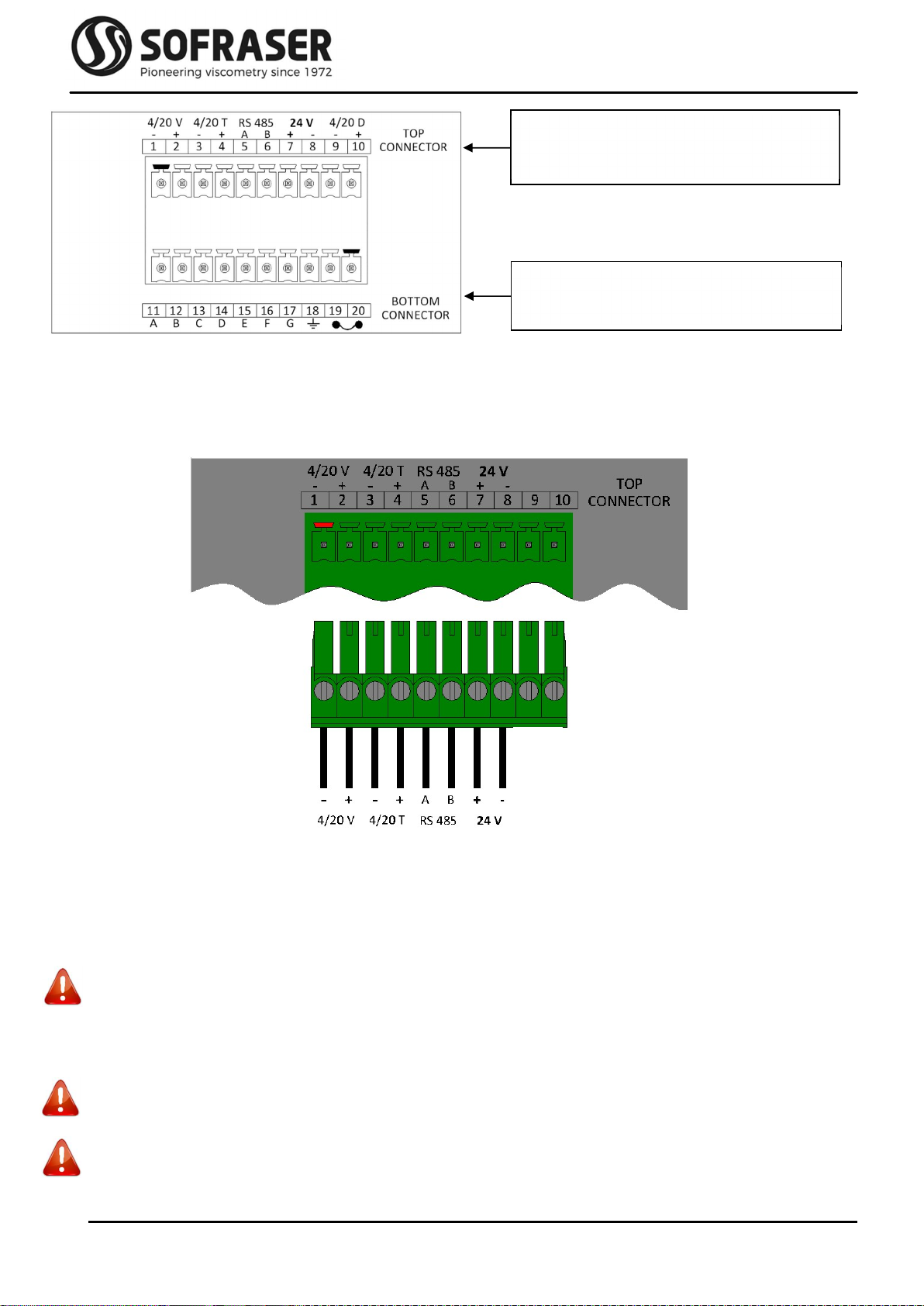
2.3 Connections
All the connections to the electronic device are made through the back panel. There are two 10-pin
green connectors plugged to the board.
As a convention, we refer to the bottom and top connectors as the terminal block screws are headed
up.
Picture 1: back panel
Technical Manual 9200
REF: 380/5 8
2.3.1
Top connector
Connections for the top connector (not cabled in our picture example) have to be made by the user
scrupulously respecting the following indications.
The plugging scheme of the top connector is as follows:
Pins 1 to 4 are 4/20 mA outputs for Viscosity and Temperature. They have been calibrated according
to customer's request. They must be connected to installations with an impedance of not more
than 350. It is recommended to use armed cables for these outputs and the shield should be
pressed in the earth terminal screw. They are already powered internally.
When the measured value is out of the configured range of the 4/20 output (below minimum value
or over maximum value), the output passes in default mode and is forced to 22 mA.
Never connect the 4/20 mA outputs to a power supply, an active PLC input or tester
Pins 5 and 6 are used to connect the RS-485 cable in order to communicate with an external
console.
Pins 7 and 8 are for the 24 VDC (± 2.4 V) stabilized and filtered power supply.
Caution: watch out the polarity
Pins 9 and 10 are not used.
Caution: Do not plug anything.
Interface to the outside world
(Outputs and power supply)
Links to the MIVI sensor and earth
grounding
Technical Manual 9200
REF: 380/5 9
*
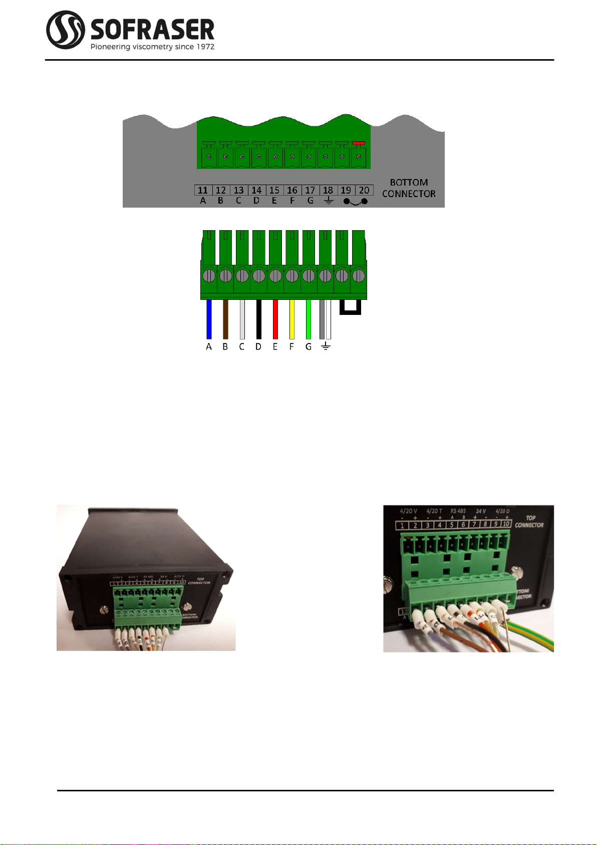
2.3.2
Bottom connector
The plugging scheme of the bottom connector is as follows:
Pins 11 to 14 make the connection between the electronic board and the MIVI sensor itself. This is
how the driving signal is generated and how the receiving signal is measured.
Pins 15 to 17 are used to connect the Pt100 probe wires.
Pin 18 is the Earth connection.
* The white wire of the MIVI is only present for intrinsically safe version of the sensor. For other
configurations, this white wire is cut and only the metal wire is connected to Pin 18.
Pins 19 and 20 are not used. By default, a wire makes the shortcut between the two pins (see picture
2).
Picture 2.1: bottom connector
When the cable is short and the
sensor is correctly earth grounded
Picture 2.2: bottom connector
It may be necessary to earth ground the
transmitter directly on PIN18
Technical Manual 9200
REF: 380/5 10
3. The 9200 operating functions
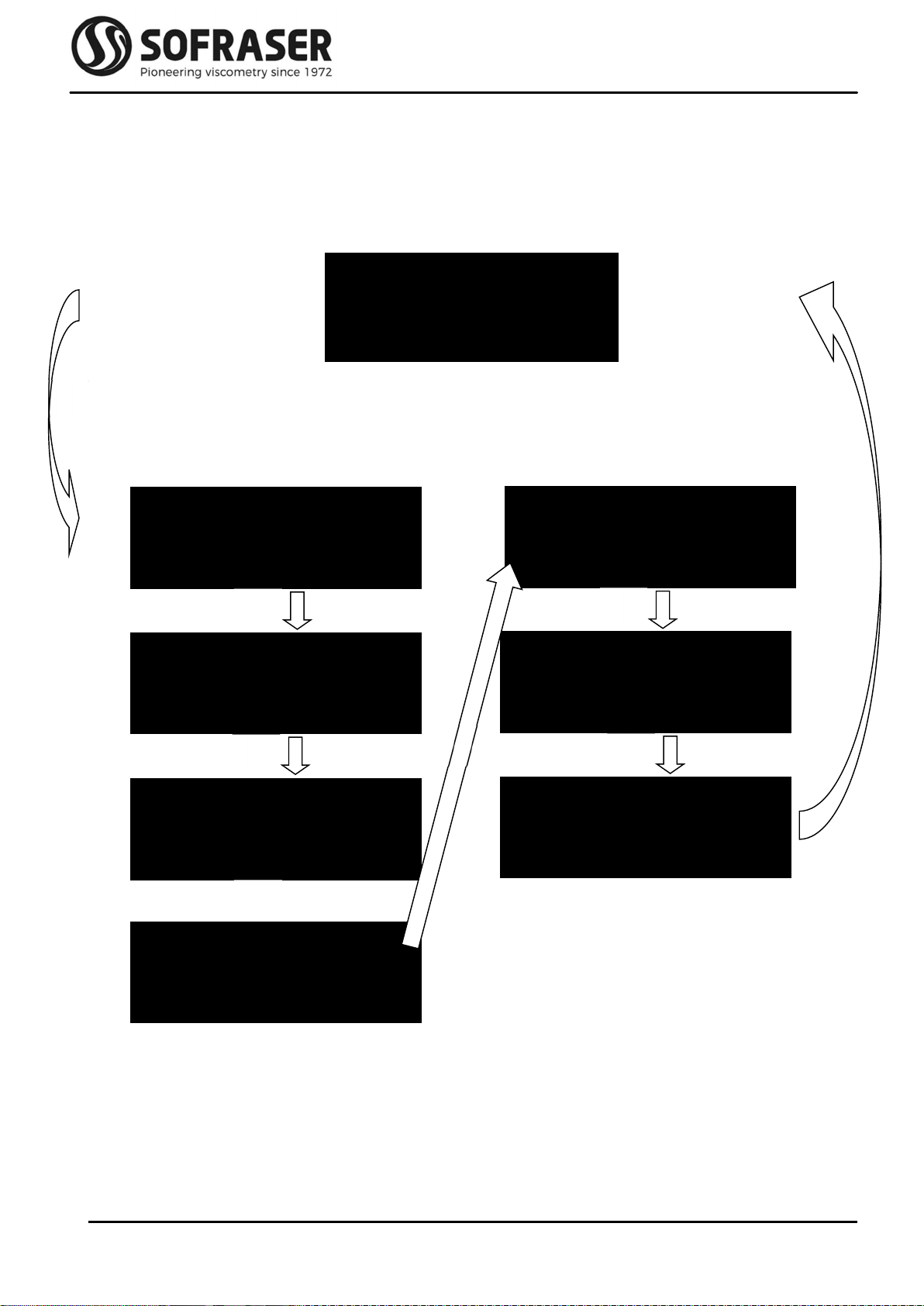
3.1 Start and menus
After turning on the device, the LCD screen switches on and it will take a few seconds to display the
measured viscosity and temperature values.
This is the main screen, the one displayed in working mode.
By pressing the “Home” button (small house icon), we get access to the seven different menus
proposed by the processor. We can browse from one to the other with the help of Home. To
enter into a menu, one must press OK.
If you keep the Home button pressed during 3 seconds you will automatically move back to the
main screen of the 9200 displaying the viscosity and the temperature.
Visc: 105.3 mPa.s
Temp: 25.36 °C
Temperature Unit
°C
Viscosity Unit
cP
Correlation
None
Raw values Check 4-20mA
Offset
7
Temperature
Enabled

Technical Manual 9200
REF: 380/5 11
OK
3.2 Raw values
This menu has two screens. It allows the user to read the raw values of the main measured signals
and other information specific of the unit.
Mainly, these data are used to diagnose when something wrong happens with the sensor.
On the first screen are displayed:
The amplitude value, image of the amplitude of the oscillating rod with no correction and
no calculation.
The coil value, image of the inner temperature.
The frequency of the vibration.
The program version is displayed for after-sale purposes.
And on the second screen are displayed:
The serial number of the electronics (3 letters) and of the sensor (4 digits).
The date of manufacturing.
The inner temperature.
The viscosity range of the sensor.
Exit this menu by pressing Home.
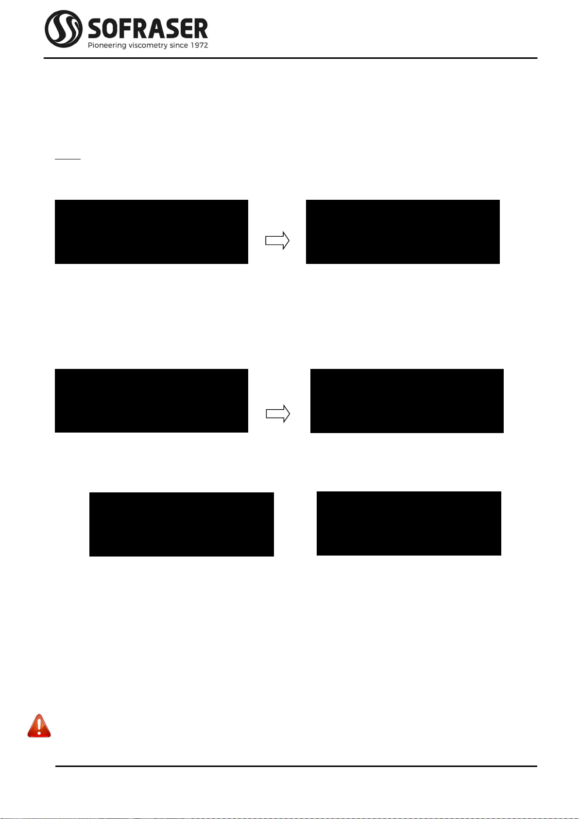
3.3 Offset
In this menu, we set the zero in the air. This is a very important step in the installation procedure of
the equipment and it must be done each time the sensor is installed again after being
removed for cleaning, calibration or maintenance.
Before proceeding to the zero setting, the rod must be clean and dry. Be sure the process is empty
and that the rod is vibrating in the air. The sensor must be fixed on its final position and will
have to remain so. If not, the offset calibration will have to be done again.
Press OK to enter the Offset menu. The warning window with the message for having the rod clean
and dry appears. If OK is pressed, the new adjustment value (here -26) is displayed. The user
can validate the new offset pressing OK or he can get out of the menu by pressing Home.
Off. Acquisition
Rod Clean & Dry
OFFSET -26
Confirm with OK
OK
AMP 1179 COIL 5033
FRQ 287 PROG 530
OK
FZW 5853 04/2019
TC26°C 500
OFFSET -26
Cancel with HOME
Technical Manual 9200
REF: 380/5 12
The viscosity signal delivered to the outputs of the electronic device is calculated by using the
adjusted amplitude of the rod. If the offset is done in a wrong way or has been forgotten, the
viscosity value will be wrong.
It is THE essential setting during installation and has to be performed with the most extended
attention in order to set the MIVI in its best conditions for optimal measurements.
Note:
The user should wait at least one minute between two zero adjustments, in order to get
accurate signals and calculations.
If the offset is not done correctly, a warning message will appear as follows:
This message appears automatically when the offset value is too high (or too low in the negative). If
so, check that the sensor is correctly installed on the process, with the vibrating rod clean and
dry and let the unit stabilize. Then redo the zero in the air procedure.
If this message remains even after carrying all the precaution recommended by Sofraser, the end-
user can anyway validate the Offset value by pressing OK and then OK again after a last
validation screen.
3.4 Viscosity and temperature units
It is possible to select the viscosity and the temperature units for the main display on the LCD screen.
Press OK to enter the menu, choose between the different units by pressing OK and validate the
choice with Home.
The choices are cP, P, mPa.s, Pa.s and no unit for the viscosity and degree Celsius (°C) or degree
Fahrenheit (°F) for the temperature.
3.5 Check 4-20 mA
In the same checking approach, this menu lets the user check the good calibration of the 4-20 mA
outputs. In this function, we ask the processor to send three different known current values to
the outputs and the user has to check with the help of an ammeter the value which is delivered
on the pins 1-2 and 3-4 of the top green connector.
Do not use an active tester (write mode), only use a passive tester like an ammeter (read mode).
Temperature Unit
°C
Viscosity Unit
cP
( ! ) OFFSET -735
See Manual
OK Validate Offset?
NO=Home YES=OK
Validate Offset?
NO=Home YES=OK
OK Are you sure?
NO=Home YES=OK

Technical Manual 9200
REF: 380/5 13
By pressing OK, it sends the first current value (04 mA). Then by browsing with OK, it goes to the
next two values (12 mA and 20 mA).
Exit the menu by pressing Home.
3.6 Correlation
This menu allows the user to enable or disable the correlation function. After positioning on the
Correlation menu change the status by pressing OK and exit by pressing Home when the
desired status is reached.
It is necessary to use the Sofraser Interface Software (SIS, see chapter 5) to choose the type of
correlation (Linear with ax + b formula or Table) and to change the values of correlation.
When the correlation is activated, an asterisk * appears on the bottom right corner of the main
screen (see chapter 2.1).
Check 4-20mA 12 mA
20 mA
OK OK
OK
OK
OK
Correlation
None
Correlation
Equation
OK
Correlation
Table
OK
04 mA

Technical Manual 9200
REF: 380/5 14
3.7 Enable or disable temperature
This menu allows the user to enable or disable the display of temperature on the main screen. After
positioning on the Temperature menu, change the status by pressing OK and exit by pressing
Home when the desired status is reached.
OK
Temperature
Enabled
Temperature
Disabled
OK

Technical Manual 9200
REF: 380/5 15
4. RS485 frame protocol
Goal: read viscosity and Pt100 values using RS-485 communication
S: send from the console to the board
R: response from the board to the console
Viscosity: viscosity in the unit displayed on the 9200 screen (cP, P, mPa.s or Pa.s)
Pt100: value in the unit displayed on the 9200 screen (°C or °F) of the temperature read by the probe
when there is one
COM port characteristics:
Speed: 9600 bits/s Number of bits: 8 Parity: none Stop bit: 1
Generic frame format (all the data in the frames are in Hexadecimal)
S = SN 04 XX XX YY YY <CRC-16>
R = SN 04 AA {DATA} <CRC-16>
SN: slave number 04: reading function
XX XX: starting point for the addresses to be read YY YY: number of words to be read
AA: read bytes number DATA: content of all the asked addresses
<CRC-16>: checksum Modbus RTU on 16 bits (can be automatic if PLC or software is compatible)
NB: 1 word = 2 bytes
List of addresses:
The viscosity value read through the RS-485 is the viscosity displayed on the 9200 main screen
multiplied by a factor which depends of the viscosity range of the unit.
Therefore, the viscosity read through the RS-485 has to be divided by a factor in function of its full-
scale range and which is indicated in the table below:
Full scale range Multiplied factor
0 to 3,999 mPa.s 1,000,000
4,000 to 39,999 mPa.s 10,000
Above 40,000 mPa.s 1,000
Data to read
Address in
Hexadecimal
Number of
words
Multiplied factor of
the data received
Frame to send with a
unit at slave address 01
Viscosity
(in cP, P
mPa.s or Pa.s)
0x 00 14
2 words
4 bytes
(UINT_32)
1,000
or 10,000
or 1,000,000
(see table below)
01 04 00 14 00 02 31 CF
Temperature
(in °C or °F)
0x 00 12
2 words
4 bytes
(INT_32)
100,000 01 04 00 12 00 02 D1 CE

Technical Manual 9200
REF: 380/5 16
Example 1: to read the viscosity of a unit which has a slave address 01 (01 in Hexadecimal), with a full-
scale range of 100 mPa.s and which measures a viscosity of 67.65 mPa.s
S = 01 04 00 14 00 02 31 CF
R = 01 04 04 04 08 4F 18 4F 4C
01: slave number of the viscometer in Hexadecimal 04: reading function
00 14: viscosity address 00 02: number of words 31 CF: checksum of sending frame
04: number of bytes read 04 08 4F 18: viscosity value in Hexadecimal which is converted to
67,653,400 in Decimal and this value has to be divided by 1,000,000
(because range is below 4,000 mPa.s) so the viscosity is 67.65 mPa.s
4F 4C: checksum of receiving frame
Example 2: to read the viscosity of a unit which has a slave address 01 (01 in Hexadecimal), with a full-
scale range of 10,000 mPa.s and which measures a viscosity of 3,495.2 mPa.s
S = 01 04 00 14 00 02 31 CF
R = 01 04 04 02 15 54 DC D4 A1
01: slave number of the viscometer in Hexadecimal 04: reading function
00 14: viscosity address 00 02: number of words 31 CF: checksum of sending frame
04: number of bytes read 02 15 54 DC: viscosity value in Hexadecimal which is converted to
34,952,412 in Decimal and this value has to be divided by 10,000
(because range is between 4,000 and 39,999 mPa.s) so the viscosity is
3,495.2 mPa.s
D4 A1: checksum of receiving frame
Example 3: to read the temperature of a unit which has a slave address 01 (01 in Hexadecimal), which
measures a temperature of 25.92 °C
S = 01 04 00 12 00 02 D1 CE
R = 01 04 04 00 27 8C FE AE CF
01: slave number of the viscometer in Hexadecimal 04: reading function
00 12: temperature address 00 02: number of words D1 CE: checksum of sending frame
04: number of bytes read 00 27 8C FE: temperature value in Hexadecimal which is converted to
2,591,998 in Decimal and this value has to be divided by 100,000 (always
the same factor) so the temperature is 25.92 °C
AE CF: checksum of receiving frame

Technical Manual 9200
REF: 380/5 17
5. Sofraser Interface Software
The Sofraser Interface Software (SIS) has been designed for working with the 9200 electronic device.
It allows the communication between the electronic board of the 9200 and a computer in
order to make some data logging or to set some parameters.
This software has been designed to work on Windows XP, Windows Vista, Windows 7 and Windows
10 systems. The communication is established through the RS485 port, MODBUS (code RTU)
protocol.
This is optional and is not included in standard with 9200 device.
5.1 The main features
The main features of the SIS are as following:
display and refresh the dynamic values from the sensor: viscosity, temperature (when there
is a Pt100 probe), amplitude, coil and frequency signals
make the zero adjustment in the air
data log of the dynamic values in an Excel file
adjust some correlations for the viscosity
5.2 The user-friendly interface
When connecting the 9200 to a computer, choose the COM port on which is connected the
viscometer. Then click on the double arrow button; the SIS will automatically detect the board,
display the serial number of the device and open a new window. The user is ready to start
working with the equipment.
Each equipment is protected with a registration. At first use, you will have to activate the software
by entering the registration key given by Sofraser (go to menu “File\Add Sensor” or “F6”). From
then on, the SIS installed on this computer will always be able to communicate with the 9200.
Different levels of security have been set up in the SIS, so that different users can have different
possibilities on the equipment through menu “Options\Connect As” or “F9”.
User Password
Technician 1111
Manager 1111

Technical Manual 9200
REF: 380/5 18
6. Troubleshooting
The hereunder table lists all the reasonable malfunctioning and some advices in order to analyze
them and to fix them:
Observed malfunctioning Checking advice
The screen does not light on when we turn
on the power supply.
Check the wiring connections and the
power supply of the equipment (see § 2.2.1
and 2.3.1).
If it does not solve the problem please
contact Sofraser or your distributor.
The sensor is not vibrating but the screen
lights on.
Check the resistor value between wires A
and B (PIN 11 and 12) and between wires C
and D (PIN 13 and 14).
The screen displays Out Of Range instead of
the viscosity.
The viscosity measured is over the calibrated
range of the unit.
Contact Sofraser or your distributor for a
new calibration.
The screen displays Sensor BREAK.
Check the connections of the wires A to D of
the MIVI sensor on PIN 11 to 14 on the bottom
connector (see § 2.3.2).
The screen displays Pt100 BREAK.
Check the connections of the wires E to G of
the MIVI sensor on PIN 15 to 17 on the
bottom connector (see § 2.3.2).
If the MIVI sensor is not equipped with a
Pt100, just disable temperature
measurement (see § 3.7)
The screen displays an asterisk * on the
bottom right corner.
It indicates that a correlation is activated
(see § 3.3.6).
The temperature is not displayed on the
main screen.
The temperature feature is deactivated (see
§ 3.3.7 to activate it).
The value of the current 4-20 mA output is
not consistent with the measured value
displayed on the main screen.
Check the range of the current output in the
specific notes.
Contact Sofraser or your distributor if the 4-
20 mA output range must be modified.
There is no signal on the current output. Contact Sofraser or your distributor.
Table of contents
Other Sofraser Transmitter manuals


