5140241-100 rev 3 Instrumentarium Dental i
Table of Contents
1 Introduction..................................................................................................................1
1.1 General .................................................................................................................1
1.2 Exhibition mode.....................................................................................................1
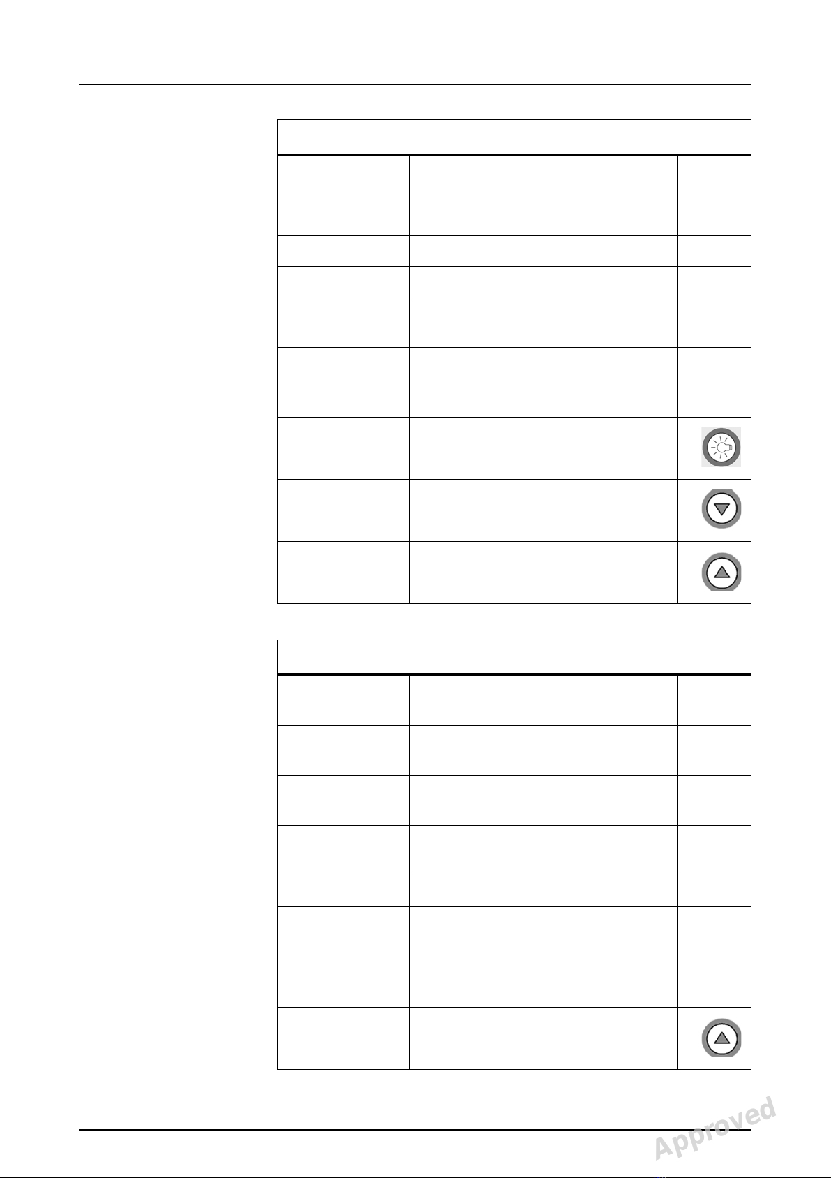
1.3 Service program quick reference..........................................................................2
1.4 How to use the service programs..........................................................................4
2 Service program features ...........................................................................................5
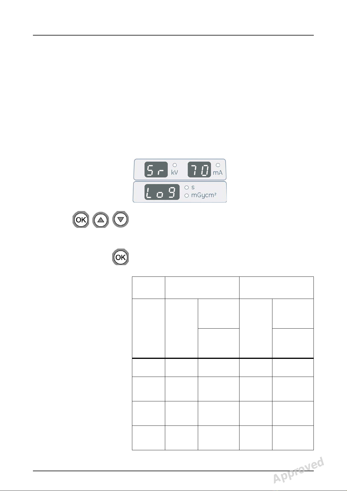
2.1 Sr 70 Log: Display error log ..................................................................................5
2.2 Sr 71 PAy: Set lease period..................................................................................7
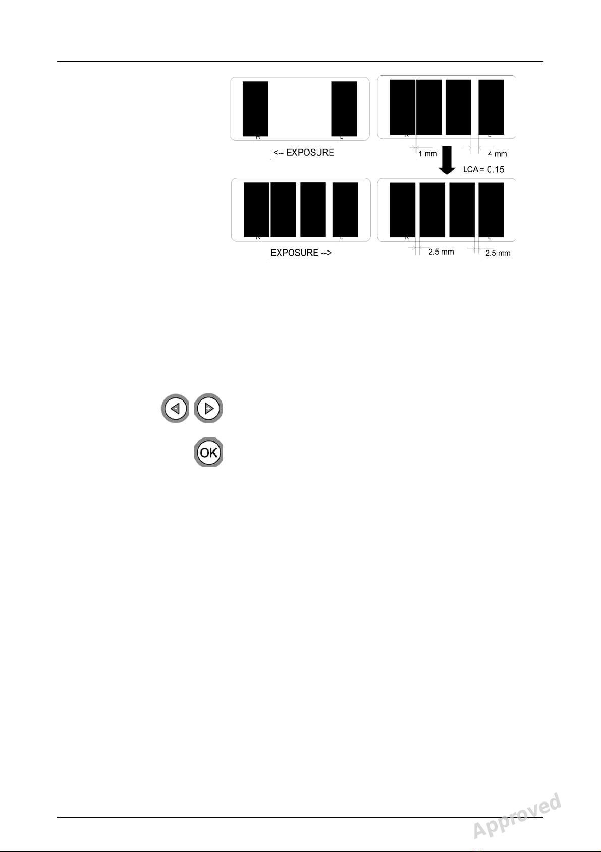
2.3 Sr 72 LCA: Adjust lateral TMJ image area
(film units only)......................................................................................................8
2.4 Sr 74 IOC: Display CPU input/output signal check.............................................10
2.5 Sr 76 PUP: X-ray tube warm-up..........................................................................16
2.6 Sr 77 Prh: Adjust the preheat setting..................................................................18
2.7 Sr 78 thA: Set Dose Calibration Constant (DCC)................................................19
2.8 Sr 79 SUP: Display line voltage..........................................................................20
2.9 Sr 80 CrL: Test motor movement........................................................................20
2.10 Sr 81 bPL: Display biteplate properties
(Volumetric Tomography option only).................................................................22
2.11 Sr 82 COL: Set/display collimator information ....................................................23
2.12 Sr 86 Sto: Store settings.....................................................................................25
2.13 Sr 87 LAL: Set linear adjustment value for VT....................................................25
2.14 Sr 88 CAL: Disable automatic cephalostat alignment correction
(digital units only)................................................................................................26
2.15 Sr 88 CAL: Set cephalostat alignment value (film units only) .............................27
2.16 Sr 89 COP: Set country options..........................................................................27
2.17 Sr 90 PIN: Panorama installation program..........................................................30
2.18 Sr 91 CIN: Cephalostat installation program (digital units only)..........................31
2.19 Sr 92 CHE: Set level of self-checks....................................................................32
2.20 Sr 93 BAL: Adjust beam alignment board sensitivity ..........................................33
Approved: Äärynen Teemu 2008-05-19 06:07
Reviewed: Rintamäki Markus 2008-05-16 15:20
Approved
See PDM system to determine the status of this document. Printed out: 2015-04-10 11:50:57
D500293, 3
Copyright © 2008 by PaloDEx Group Oy. All rights reserved.