Instrumentation and Engineering Services VFR 1 User manual

Instrumentation and
Engineering
Services, Inc.
VFR 1 Recorder
USER MANUAL
Tel. 850-244-2128 151 Mary Esther Blvd., Suite 311
Fax 850-244-7979 Mary Esther, FL 32569
Tel: 1-850-515-1244
Fax: 1-850-515-1245
IES, Inc.
7552 Navarre Parkway Suite 42
Navarre FL 32566

VFR 1............................................................................................................................... 1
Overview...................................................................................................................... 1
Specifications............................................................................................................... 1
Electrical .................................................................................................................. 1
Power ....................................................................................................................... 2
Physical.................................................................................................................... 2
Operational Theory ...................................................................................................... 2
Control Logic........................................................................................................... 2
Analog-to-Digital (A/D) Converter ......................................................................... 3
Memory.................................................................................................................... 3
Micro-controller....................................................................................................... 3
Oscillator Speed....................................................................................................... 4
Amplifier Gains ....................................................................................................... 4
Amplifier Bias.......................................................................................................... 4
Triggering Modes..................................................................................................... 4
Recorder Operational Modes ....................................................................................... 5
Sleeping.................................................................................................................... 5
Standby .................................................................................................................... 5
Recording................................................................................................................. 5
Awaiting T1 ............................................................................................................. 5
Data Downloading ................................................................................................... 5
Interface Signals Location and Description............................................................. 5
Operational Software ....................................................................................................... 9
VFR Software Program – Main Menu......................................................................... 9
Page 1 of the Main Menu......................................................................................... 9
Page 2 of the Main Menu....................................................................................... 20
Page 3 of the Main Menu....................................................................................... 31
VFR Software Program – Display Data..................................................................... 35
Encapsulation................................................................................................................. 47
Epoxy-Casting............................................................................................................ 47
Compound Formulation......................................................................................... 47
Mold Preparation ................................................................................................... 47
Container Preparation ............................................................................................ 47
Compound Preparation .......................................................................................... 48
Compound De-aeration.......................................................................................... 48
Compound Application.......................................................................................... 48
Compound Cure..................................................................................................... 48
Recorder Packaging ................................................................................................... 49
Epoxy Encapsulation ............................................................................................. 49
Glass Bead Encapsulation...................................................................................... 49
Paraffin Encapsulation........................................................................................... 49
Appendix A.................................................................................................................... 51
Example VFR Settings............................................................................................... 51
Appendix B .................................................................................................................... 56
VFR 1 Signal Locations............................................................................................. 56

VFR 1
Overview
The VFR1 is a reusable, compact, high shock, solid-state, recorder designed to acquire
data in hostile test environments. The epoxy-encapsulated unit was designed to fit inside
of a general-purpose bomb fuze booster cup. By installing the recorder in the place of the
fuze booster and lead, the user is able to record the impact acceleration event as well as
several analog and eight digital events.
The VFR1 can be programmed for various trigger modes, filter frequencies, sample rates,
amplifier gain, and amplifier bias. All of the programmable features are available to the
user through a menu-driven computer operating system (operating in a Windows
environment). On-line computer aided assistance is available to the user when setting-up
the amplifier gain and bias. The user has a visual display of the recorder range and zero
settings rather than relying on calculations.
Low power consumption allows the test instrumentation to be built weeks before the test
and extends the time for data retrieval. After a test, the recorder data is retrieved using a
personal computer and the same computer operating system that is used to program the
recorder.
Specifications
Electrical
Number of Programmable Analog Channels.......................................................................1
Number of Buffered Analog Channels ................................................................................2
Number of Digital Channels ................................................................................................8
Analog Channel Sample Rate (High Speed)...........................................................57.8 kHz
Analog Channel Sample Rate (Low Speed 0) ........................................................28.9 kHz
Analog Channel Sample Rate (Low Speed 1) ..........................................................7.2 kHz
Analog Channel Sample Rate (Low Speed 2) ..........................................................1.8 kHz
Analog Channel Sample Rate (Low Speed 3) ...........................................................451 Hz
Analog Channel Sample Rate (Low Speed 4) ...........................................................112 Hz
Analog Channel Sample Rate (Low Speed 5) .............................................................28 Hz
Analog Channel Sample Rate (Low Speed 6) ...............................................................7 Hz
Analog Channel Sample Rate (Low Speed 7) ............................................................1.8 Hz
Analog Channel Signal Bandwidth......................................... Selectable 2.3kHz or 9.3kHz
Analog Channel Amplitude Resolution ..................................................... 256 digital steps
Analog Channel (Programmable) .......................................... Filter8-pole elliptic low-pass
Total Storage Capacity.........................................................524,288 data words (512K x 8)
External Trigger 1 Signal.................................................................... 3.0 to 10.0-volt pulse
External Trigger 2 Signal...................................................................... 2.3 to 3.3-volt pulse
External Trigger 2 Input Impedance.................................................................10,000 ohms
Internal Trigger ...................................................................................Slope Programmable
Internal Trigger ................................................................................... Level Programmable
1

Power
Supply Voltage...................................................................................................6 to 15 volts
Standby Current ............................................................................ 450 micro amps (typical)
Operating Current ..............................................................................10 milliamps (typical)
Data Retention Current ................................................................. 450 micro amps (typical)
Sensor Reference Voltage........................................................................................3.3 volts
Sensor Supply Current (Per Channel)...........................................20 milliamps (maximum)
Physical
Shock Survivability................................................................................................100,000 g
Temperature Range.........................................................................................32oF to 160oF
Temperature Range (With Screening) .......................................................... -65oF to 160oF
Encapsulation.............................................................................................................. Epoxy
Size (VFR #1) ........................................................................................See Figure 1 Below
Figure 1. VFR 1 Size
Operational Theory
Figure 2 shows a simplified block diagram of the VFR1. The major components of the
recorder are the control logic, the memory, the analog-to-digital (A/D) converter, and the
micro-controller. Following is a description of each functional block.
Control Logic
The control logic provides the control logic that enables data collection when the recorder
is triggered, places the recorder in a data retention mode when the incoming data has
filled the memory, and enables an external computer to interrogate the memory to extract
the data. The control logic also provides correct timing for writing the data into memory
and sequentially addresses all available memory locations.
2

Figure 2. Block Diagram of VFR 1
Analog-to-Digital (A/D) Converter
The recorder utilizes a CMOS 8-bit A/D converter for digitizing data. The control logic
selects the sampling rate. The A/D contains a multiplexer that is controlled by the control
logic. The multiplexer sequentially switches the A/D input through all of the available
channels, samples the channel output, digitizes the sampled level, and then places the 8-
bit digital word on the data bus for transfer to memory.
Memory
The data storage device used is a CMOS low-power static, random access memory. The
recorder storage capacity is 524,288 data words (512K x 8 bits). Each sample digitized
by the A/D is an eight-bit word and is stored as a data word in the memory. The A/D
sequentially samples each analog channel, generating a data word for each and writing it
in memory. Once all of the analog channels have been sampled, an addition eight-bit
data word is written in memory. This data word contains the information from the eight
digital channels.
Micro-controller
The micro-controller is the brain that enables the recorder flexibility. The laboratory
computer communicates with the recorder through the micro-controller. The micro-
controller accepts recorder configuration data from the laboratory computer through an
RS-232 serial link. The configuration data contains instructions for oscillator speed,
amplifier gains, amplifier bias, and triggering modes.
3

Oscillator Speed
The oscillator speed controls the recorder sample rate. The VFR1 has one high speed and
eight low speed options for the oscillator. The low speed is programmable and can be
changed between tests. Table 3-1 lists all of the available sample rates, the sample
periods, and the recording time available at that rate.
Amplifier Gains
SAMPLE RATE SAMPLE PERIOD RECORDING TIME
57.8 kHz .017 mSeconds 2.268 Seconds
28.9 kHz .035 mSeconds 4.535 Seconds
7.2 kHz .138 mSeconds 18.141 Seconds
1.8 kHz .553 mSeconds 72.566 Seconds
450 Hz 2.215 mSeconds 4.838 Minutes
112 Hz 8.858 mSeconds 19.351 Minutes
28 Hz 35.433 mSeconds 77.404 Minutes
7 Hz 141.730 mSeconds 5.160 Hours
Table 1. Oscillator Sample Rates and Recording Times
The amplifier gain sets the full-scale level of the data window. It is similar to setting the
volts/division on a laboratory oscilloscope. The gain adjustment allows the user to
reconfigure the recorder for different test requirements and different sensors. Unlike
other commercially available recorders requiring gain calculations using complex
formulas followed by gain settings through the installation of a calculated resistor value,
the VFR1 is programmable using a laboratory computer.
Amplifier Bias
The amplifier bias adjustment is similar to adjusting the vertical position control of a
laboratory oscilloscope. The bias adjustment allows the user to select the zero location of
the data amplitude. The bias adjustment allows the user to reconfigure the recorder for
different test requirements and different sensors.
Triggering Modes
The user is able to program the recorder, for either the standard G-switch triggering
and/or an auto-triggering mode. In the auto-trigger mode, the micro controller monitors
the recorder channel zero output and generate a trigger 2 signal when the signal crosses a
bit threshold. The bit level selection for triggering the recorder when in the auto-trigger
mode is programmable by the user so the level can be changed between tests or it can be
disabled. The auto-trigger allows the recorder to be triggered in the same manner that a
laboratory oscilloscope is triggered. If a G-switch is attached to the normal trigger pads,
4

the recorder is triggered by the first signal generated, either the G-switch or the au
trigger. The G-switch ca
to-
nnot be disabled; it must be removed to prevent it from
gering the recorder.
ecorder Operational Modes
ta downloaded while the
rial link is connected, but the analog section remains off.
the
ctive, so signals can be connected to the recorder to test/calibrate the analog section.
d
not filled up), the “Stop” button
ust be pressed before the data can be downloaded.
rify
status indicates it is “Awaiting External T1”, the
rial connection can be removed.
rd
nd with a cross hair, obtain timing and amplitude information and print the display.
ll of the VFR1 signal locations. Following is a description of each
al.
trig
R
Sleeping
Sleeping indicates the recorder is in the low current mode. It draws 10-14 mA while the
serial link is connected. When the serial is disconnected, the recorder draws under 500
uA and is dormant. The recorder can be programmed, and da
se
Standby
Standby indicates the analog section of the recorder is powered, but data is not being
stored into memory. This mode is useful for measuring the data collection current of
recorder because the sensors are powered in this mode. Also, the analog outputs are
a
Recording
Recording data indicates the analog section is on and the recorder is actually storing data
into memory. When the memory is full, the recorder will automatically turn itself off and
go into the “Sleep” mode to conserve power. If the recorder is recovered after a test, an
it is still in the “Recording” data mode (memory was
m
Awaiting T1
Awaiting External T1 indicates the recorder is in the “Sleep” mode, waiting for the
correct external 3.3-volt pulse on the T1 pin of the recorder to wake it. The external pulse
is ignored when the serial link is on. When T1 occurs, the recorder will automatically go
into the “Recording” mode, sampling at the slow sampling rate. Note: If there is a sensor
error, the recorder will be shut down into the “Standby” mode. So it is recommended that
the recorder be put into the “Recording” data mode on the bench, before the test, to ve
proper operation. After the recorder
se
Data Downloading
Data transfer for the VFR recorder is accomplished using the same menu-driven
computer operating system that is used to program the recorder. The software is a user
friendly, menu driven program that allows the user to retrieve, display, and store data
records. In addition, the software enables the user to magnify portions of the data reco
a
Interface Signals Location and Description
Figure 3 illustrates a
input/output sign
5

DIG 0 to DIG 7
Digital channel inputs with CMOS inputs impedance. Do not apply a voltage greater
than Vcc or less than 0 volts to these inputs.
amplifier. Do not apply a voltage
reater than Vref or less than 0 volts to this input.
al amplifier. Do not apply a voltage greater than Vref
or less than 0 volts to this input.
CH 0 +
Non-inverting input to the channel 0 differential amplifier. This signal is connected
directly to the non-inverting input of an operational
g
CH 0 –
Inverting input to the channel 0 differential amplifier. This signal is connected directly to
the inverting input of an operation
Figure 3. VFR 1 Input / Output Signal Location
CH 1 IN
Non-inverting input to the channel 1 operational amplifier. This signal is connected
directly to the non-inverting input of an operational amplifier. Do not apply a voltage
greater than Vref or less than 0 volts to this input.
6

CH 2 IN
Non-inverting input to the channel 2 operational amplifier. This signal is connected
directly to the non-inverting input of an operational amplifier. Do not apply a voltage
greater than Vref or less than 0 volts to this input.
CH 0 OUT
CH O OUT is the recorder channel 0 amplifier output. This signal is also the input for
the analog multiplexer. Use only high impedance instruments to measure this signal.
OSC OUT
OSC OUT is the output signal of the internal recorder oscillator. The frequency of the
oscillator out signal is the sampling rate of each channel. This output is not active when
the recorder in a sleep mode.
Vcc
Vcc is the regulated power supply output. This output will source 10 milliamps for an
external load.
Vref
Vref is the regulated power supply for powering sensors. This power supply is only
active while the recorder is acquiring data. This output will source 30 milliamps.
GND
GND is the power and signal ground.
SW GND
This signal is a switched ground. When the recorder is collecting data, the SW GND is at
ground potential. When the recorder is in the sleep mode, the SW GND is at Vcc level.
This single can only source/sink 1 milliamp.
BATT
BATT is a connection for an external battery. This input is not diode-coupled to any of
the other battery connections and should not be used in conjunction with any other
battery. This connection is intended to power the recorder when only one battery is used.
Use of this connection for powering the recorder eliminates the diode voltage drop that
the other battery connections have.
BATT 1
BATT 1 is a connection for an external battery. This input is diode-coupled to Battery 2
and External Power Input.
BATT 2
BATT 2 is a connection for an external battery. This input is diode-coupled to Battery 1
and External Power Input.
7

EXTERNAL POWER INPUT
EXTERNAL POWER INPUT is a connection for an external battery. This input is
diode-coupled to Battery 1 and Battery 2 inputs. This input is used by the interface box
for application of external power during the recorder programming and data retrieval.
TRIG 1
TRIG 1 is a latched input signal that provides a method of initiating the recorder data
collection operation. This trigger signal is a positive pulse that can be between the
voltage range of 3.0 to 10-volts.
TRIG 2
TRIG 2 is a latched input signal that provides a method of initiating the recorder high-
speed data collection operation. This is a CMOS input with a 10K ohm pull-down
resistor. Do not apply input signals greater than 3.3-volts to this input.
RS232-TX
RS232-TX is an RS232 level signal used for communications between the recorder and
the laboratory computer.
8

Operational Software
The operational software was written as a menu-driven computer operating
system utilizing the LabView programming language. This chapter is intended as
a user manual for the operating system. A graphics approach has been taken to
describe the operating system. Below is a display of each of the screen menu
followed by a description of each item on that menu.
VFR Software Program – Main Menu
Page 1 of the Main Menu.
This is the opening menu of the VFR program. It shows the current status
of the recorder, allows the control of the recorder, and download and display of
the data.
9
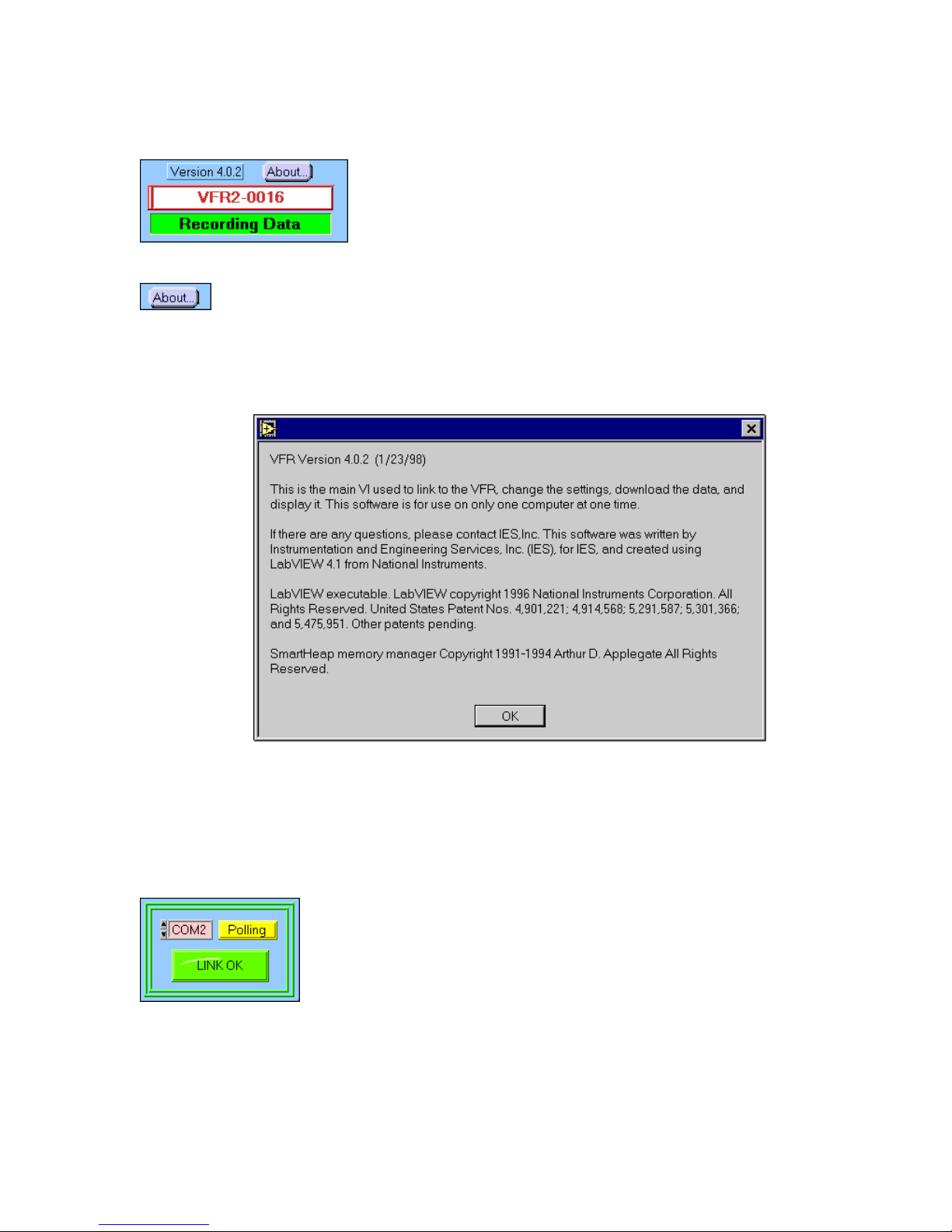
Displays the Serial Number and the current
operating status of the recorder.
Displays the program version and copyright
credits, shown below.
Allows the selection of the serial port for
communicating with the recorder. The choices
are COM1, COM2, COM3, and COM4. If the
proper port has been selected, and
communication has been established, the
“LINK OK” will turn on and the “Polling”
indicator will flash on and off.
10

The recorder cannot be found.
No serial link can be established. Possible
causes are no power to the recorder, a bad
cable connection, or the wrong serial com port
is selected.
Allows selection of different baud rates.
Note: This is the default value and should not
be changed.
Occasionally, when first connecting the
recorder to the serial port, a
“SERIAL ERROR” can occur. A beep will be
heard. This is OK, unless the recorder
continues to have error problems. It could
indicate more serious problems, such as loss
of serial link or a problem with the recorder.
Other errors can occur under “Error Status”. If
this occurs, there is a serious problem with the
recorder.
If a “Sensor Error” occurs, it means the
“Channel Auto Bias at Start” was enabled for
the channels displayed, and the recorder was
unable to set the Sensor bias when the
“START” button was pressed. The recorder will
not start recording data until the problem is
corrected. Possible solutions are disabling the
“Channel Auto Bias at Start” for that channel,
balancing the sensor, or reducing the gain for
that channel. This error could also indicate a
bad sensor or sensor wire.
11
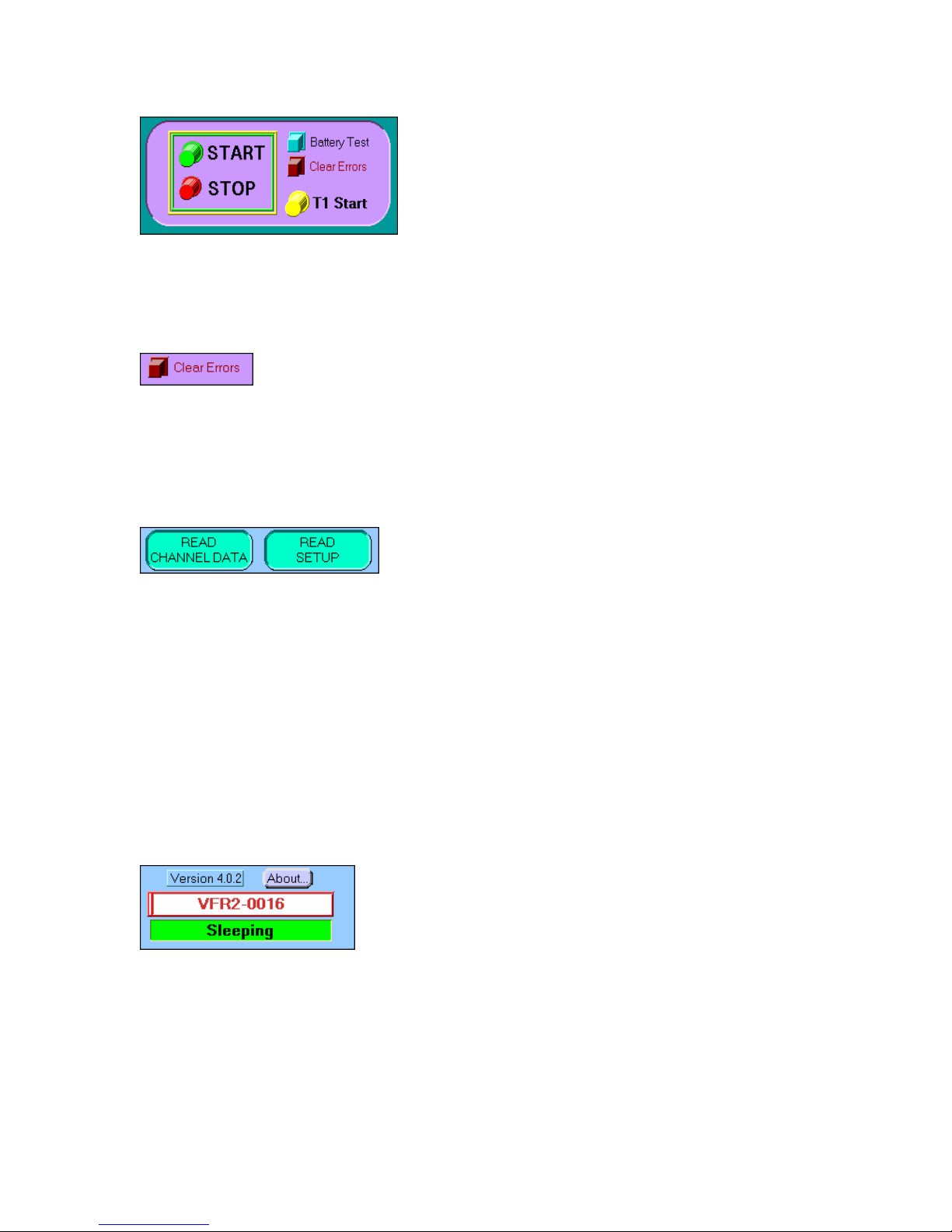
This is the main section for controlling the
recorder.
Clears any “Error Status” or “Sensor Error
Status” warnings and silences the beeping. If
the errors are not cleared with this button,
there is a more serious problem with the
recorder.
These indicators flash to remind the User to
“READ SETUP” on page 2 of the Main
program, and “READ CHANNEL DATA” on
page 3 of the Main program. This is VERY
important to do as soon as serial link has been
established with the recorder. This allows the
User to verify the current settings programmed
into the recorder’s EEPROM. These will
usually flash when the recorder is first
connected to the serial port.
Note: Data can still be downloaded even if the
“READ CHANNEL DATA” or “READ SETUP”
indicators are flashing.
“Sleeping” indicates the recorder in the low
current mode. It will draw 10-14 mA while the
serial link is connected. When the serial is
disconnected, the recorder will draw under 500
uA and will be dormant. The recorder can be
programmed, and data downloaded while the
serial link is connected, but the analog section
will remain off.
12
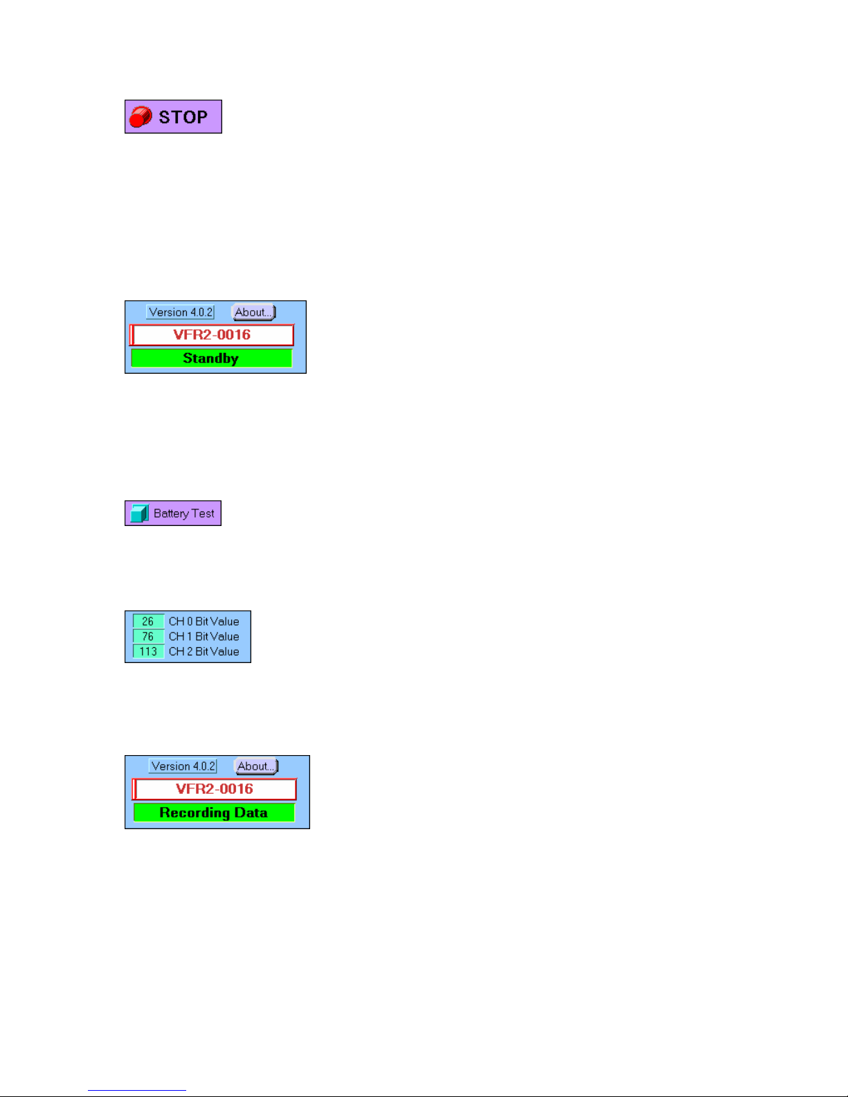
“STOP” will put the recorder into the “SLEEP”
mode if it is currently “RECORDING” data, in
“STANDBY”, or “AWAITING T1”. If the recorder
is already in the “SLEEP” mode, nothing will
happen. NOTE: If the recorder is currently
“RECORDING” data, the “STOP” button MUST
be pressed before any data can be
downloaded.
“Standby” indicates the analog section of the
recorder is powered, but data IS NOT being
stored into memory. This mode is useful for
measuring the data collection current of the
recorder, because the sensors are powered in
this mode. Also, the analog outputs are active,
so signals can be connected to the recorder to
test/calibrate the analog section.
Pressing this button will put the reocrder into
the “Standby” mode. If the recorder is in the
“Recording” data mode, this button is ignored.
When in the “Standby” or “Recording” modes,
these indicators display the analog outputs (0-
255 bits) of the amplified analog channels. In
the “Standby” mode, these values will float
towards zero.
“Recording” data indicates the analog section
is on and the recorder is actually storing data
into memory. When the memory is full, the
recorder will automatically turn itself off and go
into the “Sleep” mode to conserve power. If the
recorder is recovered after a test, and it is still
in the “Recording” data mode (memory was not
filled up), the “Stop” button must be pressed
before the data can be downloaded.
13

The “Start” button must be pressed to start
recording data. Data will start at the beginning
of the memory and sample at the “slow”
sampling rate and ALL previous data will be
erased. A message (shown below) will prompt
the User to be sure they are ready to start
recording data. Pressing “Stop” will turn off the
data recording. After the recorder is in the
“Recording Data” mode, the serial connection
can be removed.
Note: If there is a “Sensor Error”, the recorder
will put itself into the “Standby” mode, an error
will sound, and no data will be recorded. You
will need to correct the sensor problem before
recording data.
“Awaiting External T1” indicates the recorder is
in the “Sleep” mode, waiting for the correct
external 3.3-volt pulse on the T1 pin of the
recorder to wake it. The external pulse is
ignored when the serial link is on. When T1
occurs, the recorder will automatically go into
the “Recording” mode, sampling at the slow
sampling rate. Note: If there is a sensor error,
the recorder will be shut down into the
“Standby” mode. So it is recommended that the
recorder be put into the “Recording” data mode
on the bench, before the test, to verify proper
operation. After the recorder status indicates it
is “Awaiting External T1”, the serial connection
can be removed.
INFO: The recorder will start recording data
when the “START” button is pressed in the lab.
This will work in most test applications,
14

because the recorder is collecting data at a low
speed until an external T2 occurs, or the auto
trigger is activated. But certain tests require
low current and the recorder may remain
dormant for long periods of time, such as, a
sled track test. This requires the recorder to be
in the “SLEEP” mode until woken by an
external 3.3-volt signal, T1. The width of the T1
pulse required to wake the recorder can be
selected on Page 2.
The “T1 Start” button will put the recorder into
the “Awaiting External T1” mode. Pressing the
“Stop” button will turn this off and put the
recorder back into the “Sleep” mode.
Displays the current battery voltage. A good
way to determine the strength of the battery is
to apply a load to it. Pressing the “Battery Test”
button can do this. This turns on the analog
section the recorder and which loads down the
battery.
The “LOW BATT” indicator blinks when the
battery voltage is below 5.0 volts. It is highly
recommended that a new battery be used if
this occurs. The recorder monitors the battery
voltage during a test and if it falls below a safe
limit, the recorder is put into high speed and is
shut down to conserve battery voltage.
Note: If the battery voltage falls below ~5 volts
while the recorder is collecting data, the
recorder will automatically put itself into “High
Speed” until the memory is full, and shut itself
down to save battery energy and prevent data
loss.
The current recorder temperature is displayed
while the serial link is connected. Also, the
maximum temperature the recorder has seen
in its lifetime is displayed. The display can be
either in F or C.
15

After a test has been completed, the highest
and lowest temperature during that test is
displayed. These values are reset when the
“Start” button is pressed and the serial link is
disconnected.
After a test has been completed, the starting
and ending battery voltages are displayed. The
recorder starts monitoring the voltage only after
the serial link is disconnected. The voltage is
monitored about once a minute.
The current memory size. This can be selected
for 512K or 32K data points.
The memory size dedicated for each channel.
The value is determined by the mode (number
of analog channels activated) and the memory
size selected (32K or 512K data points).
The Channel mode is either “0” or “1” for the
VFR2 recorder. Mode 0 has 3 programmable
analog channels, only. Mode 1 has 3
programmable analog channels, and 4
buffered analog channels. The VFR2 recorder
has only Mode 0, which is 1 programmable
analog channel, and 2 buffered analog
channels.
Displays the current high speed and low speed
settings, which are programmed, into the
recorder.
16

Controls the downloading of the data after the
test. If the recorder is still in the “Recording
Data” mode, the “STOP” button must be
pressed first, to stop the data collection. This
will put the recorder into “High” speed until the
memory is full.
Note: The data will remain valid in memory
until either power is removed from the
recorder, or the “START” button is pressed.
Also, data can still be downloaded even if the
“READ CHANNEL DATA” or “READ SETUP”
indicators are flashing, and do not need to be
read before downloading the data.
Downloads ALL the data in the recorder. Either
32K or 512K data points, depending on how
the recorder was programmed. When
downloading, this operation can be canceled. If
there is a problem while downloading, such as,
a parity error, the User will be warned, and the
data can be downloaded again.
Sometimes when data from a test is written
into memory, not all the memory is used. In
that case, the recorder indicates the “Valid
Memory Size”. By pressing the “Quick
Download” button, only the memory, which was
used during the test, is downloaded. This
reduces the time required for downloading. If
there are any uncertainties, the User can
simply download ALL the data by pressing the
“Download ALL Data” button.
17
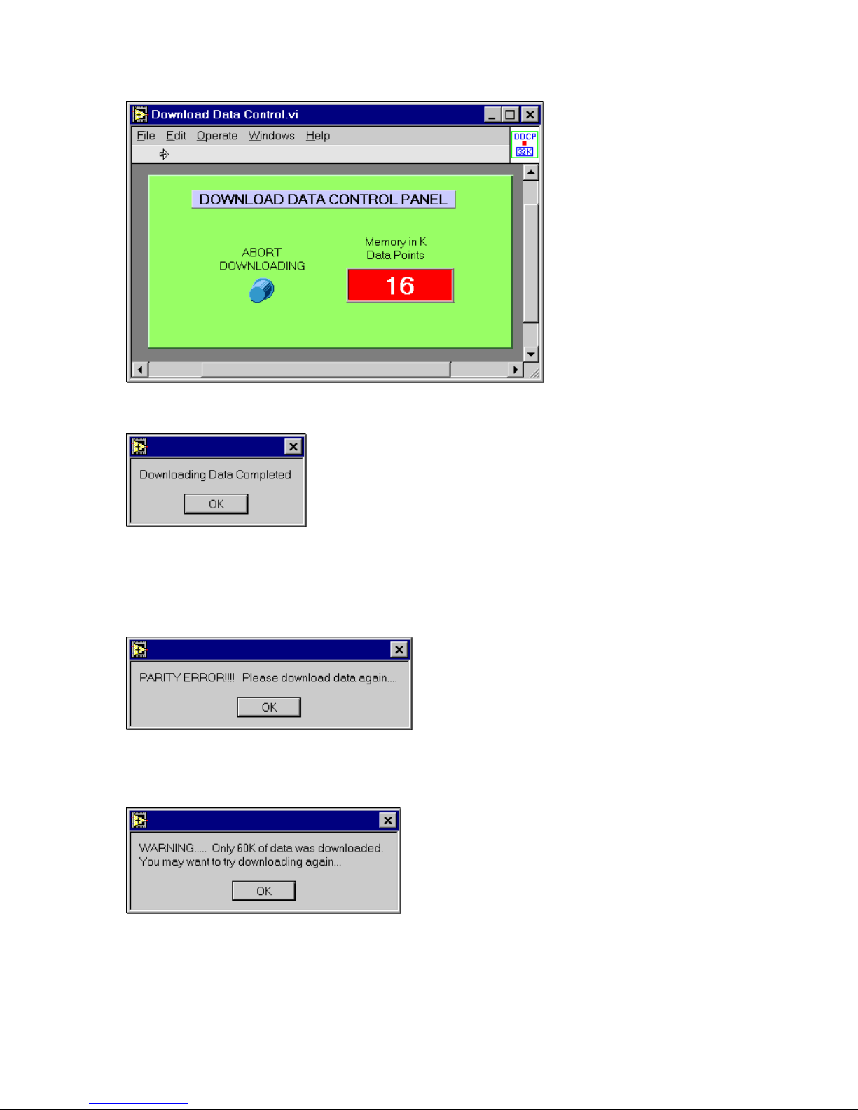
This screen pops
up when
downloading data.
The User can stop
the downloading
process by pressing
the “ABORT
DOWNLOADING”
button. It is Normal
for the memory
counter to go
slightly past the
memory size and
stop for a short
period of time.
This message is displayed when ALL the data
has been successfully downloaded from the
recorder’s memory. The data can be
downloaded as many times as the Users
wants, but it will be erased if power is removed
from the recorder, or the “START” button is
pressed.
If this message appears, there was
a problem downloading the data.
Either there was a bad connection,
or the User aborted the download
process. Simply try downloading
the data again.
This message appears if not all the
data was downloaded, indicating
how much was actually received.
18
Table of contents
Popular Recording Equipment manuals by other brands


Stereoping
Stereoping synth programmer Owner's handbook

National Instruments
National Instruments PC/104-GPIB Getting started

Mitsubishi Electric
Mitsubishi Electric DX-NT400E Operation manual

Vimar
Vimar By-alarm 01729 manual

Citronic
Citronic DSM2-6mkII manual

Siemens
Siemens XTRI-S installation instructions


