Instruments of Things SOMI-1 User manual

SOMI1 User Manual
Instruments of Things®, November 2022
Firmware Hub Version: v0.2 (CHANGELOG)
Firmware Sensor Version: v2.6 (CHANGELOG)
Editor Version: v0.1 (CHANGELOG)
1. Important Notes 3
Warning! 3
Do Not Open 3
Location 3
Water Warning 3
If you notice any abnormality 4
Intellectual Property Right 4
2. Getting Started 4
3. Overview 5
3.1 SOMI1 Hub 5
UI Elements 6
3.2 SOMI1 Motion Sensor 7
Activity parameter 8
Tilt Angle parameters 8
Acceleration parameters 9
Calibration 9
Battery 10
3.3 MIDI 10
USBMIDI 11
TRSMIDI 12
MIDI Learn 12
3.4 Technical Specification 13

4. SOMI1 Settings Editor 14
4.1 Standalone 14
4.2 SOMI1 Editor for Ableton Live Max for Live Device) 17
Setting up SOMI1 Editor for Live 17
Using SOMI1 Editor for Live 19
Using Live’s MIDI Learn Functionality 21
5. SOMI1 App 22
6. Firmware Upgrade 22
Prerequisites 22
SOMI1 Hub 22
SOMI1 Motion Sensor 23
7. Best Practices 24
8. Troubleshooting 25
9. FAQ 26
10. Declaration of Conformity 27

1. Important Notes
Please read carefully before processing
Warning!
Always follow the basic precautions listed below to avoid the possibility of serious injury
from electrical shock, short circuiting, damages, fire or other hazards. These
precautions include, but are not limited to, the following:
Do Not Open
This product contains no user-serviceable parts. Do not open the product or attempt to
disassemble or modify the internal components in any way. If it should appear to be
malfunctioning, discontinue use immediately and have it inspected by qualified
Instruments of Things service personnel.
Location
Radio waves may affect electro-medical devices.
- Do not use this product near medical devices or inside medical facilities
- Do not bring this product within 15 cm 6 in.) of anyone having a heart
pacemaker or defibrillator implant. Radio waves emanating from this product may
adversely affect a heart pacemaker implant or defibrillator implant.
Water Warning
Do not expose the SOMI1 Hub to rain, use it near water or in damp or wet conditions,
or place on it any containers (such as vases, bottles or glasses) containing liquids which
might spill into any openings. If any liquid such as water seeps into the SOMI1 Hub,
turn off the power of the hub immediately and unplug the USBC cables from power
supply. Then have the product inspected by qualified Instruments of Things service
personnel.
If you notice any abnormality
If any of the following problems occur, immediately disconnect the electric plug from
the outlet:

- It emits unusual smells or smoke.
Instruments of Things cannot be held responsible for damage caused by improper use
or modifications to the instrument, or data that is lost or destroyed.
Intellectual Property Right
The Bluetooth® word mark and logos are registered trademarks owned by Bluetooth
SIG, Inc. and any use of such marks by Instruments of Things® is under license.
Instruments of Things® is a registered trademark in Germany.
2. Getting Started
1. Wake up the SOMI1 motion sensors by touching the two metal pins on the
backside of the sensor. The LED will turn on for a short time indicating that the
sensors are ready to connect. If no connection is initiated within 10 minutes, the
sensors go back to sleep mode to prevent battery drain.
2. Lay down the sensors and make sure they are not moved due to automatic
calibration.
3. Connect the USBC device port of SOMI1 Hub USBC port in the middle) to
your end device via the included USBC cable. The hub will power on and the
LED will start pulsating blue indicating that the hub is searching for sensors.
4. Wait until the LEDs of the motion sensors start blinking, indicating an active
connection to the SOMI1 Hub. Wait about 5 seconds after the LEDs of the
sensors started blinking to let the sensors do an automatic calibration.
5. Put on the included wristbands and attach the sensors by pushing them onto the
mounting. Make sure the LED of the motion sensors are aligned to right,
otherwise some motion parameters are inverted.
6. SOMI1 is now ready to be used with any MIDI compatible software or hardware.
Check out the SOMI1 quick start guide to easily start with different setups:
https://instrumentsofthings.com/pages/somi-1

3. Overview
SOMI1 is available as a starter kit including the following components:
- 1x SOMI1 Hub
- 2x SOMI1 Motion Sensor
- 2x Wristbands
- 1x USBC to USBC Cable
- 1x SOMI1 Editor
- SOMI1 Sound app (approx. autumn 2022
If desired, more motion sensors can be added to the SOMI1 kit.
SOMI1 can be used with any MIDI capable software or hardware, as well as with the
SOMI1 smartphone app for iOS and Android, which will be available soon. Detailed data
processing parameters can be customized in real-time with the SOMI1 editor,
independently for each motion sensor and be saved directly on the SOMI1 Hub making
it suitable for DAWless setups, too.
Up to six motion sensors can be used simultaneously with a single SOMI1 Hub. The
included wristbands allow wearing the motion sensors on both the feet and wrists. The
motion sensors are waterproof and powered by CR2025 coin cells. If no connection is
active between the motion sensors and the SOMI1 Hub, the motion sensors
automatically go to sleep mode after 10 minutes. When active, the battery life lasts for
about 30 hours.
3.1 SOMI1 Hub
The SOMI1 Hub wirelessly receives the motion sensor data of the SOMI1 motion
sensors, converts them into MIDI data and outputs the MIDI data on its hardware ports.
The SOMI1 Hub offers USBMIDI (host and device) ports as well as a TRSMIDI port
making it compatible with modern and vintage electronic musical instruments
supporting MIDI. The different ports are described in more detail in the following list
(from left to right):
- USBMIDI host port (to connect SOMI1 directly to a standalone hardware
synthesizer offering an USBMIDI port)
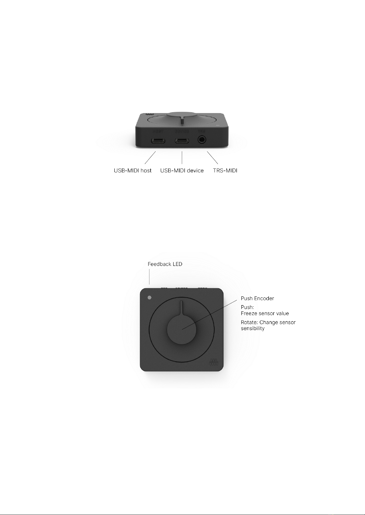
- USBMIDI device port and power supply (acts as a typical MIDI device)
- TRSMIDI port (to connect SOMI1 directly to a standalone hardware synthesizer
offering a DINMIDI port via a TRSMIDI Type-A adapter cable)
Note: No additional MIDI driver is required for common operating systems (class
compliant MIDI.
UI Elements
The LED of the SOMI1 Hub visualizes different states and interactions. For example,
while the SOMI1 Hub scans for nearby motion sensors, the LED is pulsating blue. A
description of each state represented by a specific color or animation can be found in
the following list:

LED States:
- Blue (pulsating): Scanning for nearby motion sensors to initiate a connection
- Blue (constant): Waits for Device Firmware Upgrade via Bluetooth
- White: Idle
- Red: Sensors are disabled
- Yellow: MIDI Control Change Controller is soloed
- Green: Applied currently shown settings
- Light Blue: Saved all settings to internal flash memory of SOMI1 Hub
The push encoder allows interacting directly with SOMI1. Turning the push encoder
360 degrees in clockwise direction doubles the sensitivity of acceleration X/Y/Z and
activity parameters for all motion sensors and is indicated by the LED color (fades from
blue, i.e. low sensitivity to red, i.e. high sensitivity). A short green LED color indicates
normal sensitivity or rather middle position of the push encoder. Pushing the encoder
shortly starts scanning for nearby bluetooth devices for a minute and enables / disables
processing of incoming sensor data (the current sensor value freezes). Disabling /
enabling the processing of sensor data is especially useful for live performances as you
may want to only change sound parameters during specific phases of the performance.
It’s very much the same behavior as for guitar effect pedals. A red LED indicates that
the sensors are disabled.
Furthermore the push encoder can be used to analyze the sensor data in real-time to
solo the Control Change Controller with the highest value changes. This is a very useful
feature when using MIDI Learn to map a specific movement parameter to a sound
effect. More information can be found in the MIDI Specification section.
3.2 SOMI1 Motion Sensor
Each SOMI1 sensor offers 7 different movement parameters to use 3 gyroscope
parameters (x, y, z), 3 acceleration parameters (x, y, z) and one activity parameter
(based on the velocity of the sensor, independently of a direction).
Activity parameter
Move the sensor in any direction. The parameter value depends on the velocity. To solo
the activity parameter by pushing the SOMI1 hub encoder button, make fast circular
movements.
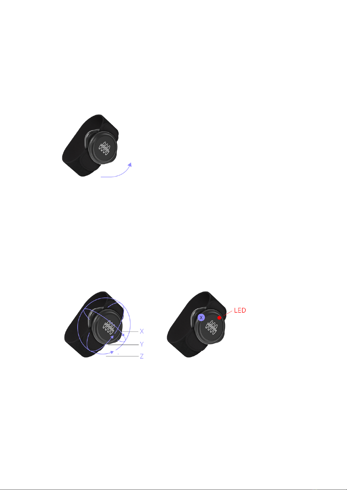
Tilt Angle parameters
Tilt the sensor around the X, Y or Z axis (left graphic). The parameter value depends on
the ankle (right graphic: X showing to the top=highest sensor value of XAxis, red
dot=LED on sensor as reference).
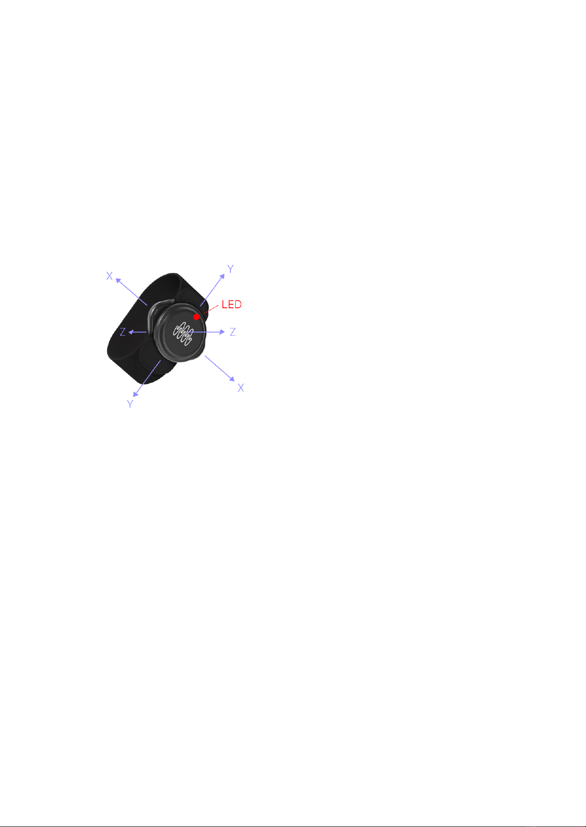
Acceleration parameters
Accelerate the sensor along the X, Y or Z axis in the positive direction. If the sensor is
not moved or moved in the negative direction of an axis (given the parameter is not
inverted), the parameter value remains at 0. With a scale factor of 1.0, the maximum
value corresponds to 4G 4x earth gravity). The earth gravity component of the
acceleration parameters is filtered out (linear acceleration) to prevent unwanted
behavior.
Calibration
To achieve highest possible precision, the motion sensors do an automatic calibration
after they have been woken up from sleep mode. The calibration takes about 3 seconds
and starts as soon as the sensor is connected to a SOMI1 Hub (i.e. LED of the motion
sensor starts blinking). During calibration, the sensors check if they are moved. If so,
the calibration won’t finish and the sensors wait until they are in a still position for
calibration. Thus, make sure to lay down the sensors after they have been woken up
and power on the SOMI1 Hub afterwards. Wait about 5 seconds after the LED has
started blinking to make sure the calibration has successfully finished.

Note: The middle position of the Tilt Z movement parameter depends on the direction
of the sensor and is set during automatic calibration. The LED of the motion sensor
corresponds to the middle position of Tilt Z.
Note: It’s recommended to always wear the motion sensors with the LED pointing to the
right direction. This makes sure that the movement parameters are not inverted and
always have the same behavior.
Battery
The motion sensors are powered by CR2025 coin cells lasting for about 30 hours. The
current battery levels can be shown in percent in the SOMI1 app and SOMI1 Editor for
Live.
To replace the battery do the following:
1. Open the battery cover using a coin as a tool.
2. Replace the battery by inserting the replacement battery first into the battery
cover, positive side up, and then pressing the sensor body on the battery cover.
Make sure that the O-ring is in correct position in the groove on the battery
cover before closing the battery cover. Please dispose of the old battery
according to the local rules and legislation, treating it as battery waste. Do not
throw it in the garbage.
3. Firmly close the battery cover. Make sure that the O-ring is not visible after
closing the battery cover.
To prevent battery drain, the motion sensors automatically go to sleep mode after 10
minutes if no connection to a SOMI1 hub is active. If a connection is active to a SOMI1
hub, the LED of the motion sensor is blinking.
3.3 MIDI
SOMI1 supports MIDI 1.0 with the following messages:
- Note On / Off
- Control Change (optional high resolution)
- Pitch Bend

The conversion of the movement data received by the sensors into MIDI data depends
on the current settings, which can be independently customized for each movement
parameter and MIDI message type. For example, one can select a desired movement
parameter, which should be used as input to control a specific Control Change
Controller. Between the conversion, one can scale the movement parameter increasing
sensitivity, changing the slew rate for rising and falling values separately, etc.
Note: High resolution 14 bit) Control Change messages are an optional feature
according to the MIDI 1.0 specification. Thus, make sure to check the MIDI specification
of the software or hardware you want to use with SOMI1 if it supports high resolution
CC.
Note: By default, each sensor uses a dedicated MIDI channel starting from channel 1
(e.g. sensor 1 uses MIDI channel 1, sensor 2 uses MIDI channel 2, and so forth).
The resulting MIDI data is output on all hardware ports of the SOMI1 Hub.
USBMIDI
The USBMIDI ports are class compliant. Thus, SOMI1 can be used in combination with
common operating systems offering a standard MIDI driver.
We have tested SOMI1 with the following operating systems:
- Mac OS
- Windows
- Linux
- iOS
- Android
If you want to use SOMI1 in combination with a host computer (e.g. laptop, mobile
device) make sure to always use the USBMIDI device port of the SOMI1 Hub (port in
the middle). This port is also used to power the SOMI1 Hub.
If you want to use SOMI1 with a MIDI hardware device offering a USBMIDI device port,
connect the USBMIDI host port of the SOMI1 Hub (port on the left) with a

corresponding USB cable to the USBMIDI device port of your hardware instrument
before powering on the SOMI1 Hub.
Afterwards use a USBC power adapter to power the SOMI1 Hub via its USBMIDI
device port.
Note: Many MIDI hardware devices offer both, a USBMIDI port and DINMIDI port. In
this case we recommend to use the USBMIDI port due to higher data transfer rate.
TRSMIDI
There are still many hardware MIDI instruments around offering a DINMIDI port only.
For this case the SOMI1 Hub offers a TRSMIDI port, which can be used with a
corresponding TRSMIDI to DINMIDI Type A adapter cable to connect SOMI1 directly
to the hardware MIDI instrument.
Note: There are two types of TRSMIDI Type A and Type B. SOMI1 uses Type A. Thus
make sure to buy the correct TRSMIDI adapter cable, for example by Make Noise.
A drawback of the classic DINMIDI port is the low baud rate 31250 baud/s) or rather
data transfer rate in comparison to USBMIDI. If SOMI1 is used with many motion
sensors simultaneously sending several MIDI messages at once, the maximum data
transfer rate may be exceeded leading to a packet loss. To address this issue, SOMI1
automatically decreases the data transfer rate for Control Change messages to save
bandwidth if a packet loss occurred. Note On / Off and Pitch Bend messages instead
are never modified to prevent unwanted behavior, for example if a Note Off message is
lost leading to a constantly pressed note.
MIDI Learn
Many hardware MIDI instruments and most MIDI compatible softwares offer MIDI Learn
functionality to easily map a specific Control Change Controller to a desired sound
parameter by selecting a sound parameter (e.g. filter cutoff) and changing the controller
value. However, SOMI1 continuously sends changes of several Control Change
Controllers simultaneously making it very hard to map the desired movement parameter
to a sound parameter.

To address this problem, SOMI1 allows soloing a specific Control Change Controller for
ease of mapping, which omits all MIDI messages except the soloed controller. A specific
controller can either be externally soloed via the SOMI1 Editor (explained in
SOMI1
Settings Editor
section) or directly via the push encoder on the SOMI1 Hub using
real-time analysis of sensor data.
Solo by using the SOMI1 editor Ableton Live users can also use the SOMI1 Max tool):
Choose your sensor in column one. Choose your desired movement parameter in
column two. Press "Solo: Active". Use the MIDI Learn function of the connected MIDI
software to map the currently soloed Control Change Controller to your desired sound
parameter. When finished creating a mapping via MIDI Learn, press "Solo: Inactive".
Solo by using real-time analysis via the push encoder of the SOMI1 hub:
To start data analysis, press the push encoder and keep it pressed constantly. The LED of
the SOMI1 Hub will start pulsating in random colors. Keep on pressing, take the motion
sensor you want to solo and move it constantly and fast along the desired movement
parameter (see section SOMI1 Motion Sensor for parameter details). Release the push
encoder while doing this movement. Now the corresponding Control Change Controller is
soloed, indicated by a yellow LED color. Use the MIDI Learn function of the connected MIDI
software or hardware to map the currently soloed Control Change Controller to your desired
sound parameter. When finished creating a mapping via MIDI Learn, press the push encoder
shortly to enable all configured MIDI messages again.
Note: A short press of the push encoder also starts scanning for nearby motion sensors
for a minute indicated by a blue pulsating LED on the SOMI1 Hub.
3.4 Technical Specification
In the following table you can find the technical specification of SOMI1.
Max. Sensors per Hub
6
Max. Distance
50 Meters1

Overall Latency
10 milliseconds2
Movement Parameter
3D Tilt X/Y/Z, 3D Acceleration X/Y/Z, Activity
Battery Lifetime
Min. 30 Hours when active3
Wireless Protocol
Custom Bluetooth® 5 based)
MIDI Version
1.0
Supported MIDI messages
Control Change 14 Bit), Note On / Off, Pitch Bend
MIDI Interface
USBC Device, USBC Host, TRS Type A
UI Elements
Push Encoder, RGB LED
1may vary depending on environment
2depends on selected audio buffer size of external software
3automatic sleep mode if no connection is active for 10 minutes
4. SOMI1 Settings Editor
SOMI1 comes with two separate editors allowing detailed customization: a standalone
editor and an editor specifically for Ableton Live Max for Live).
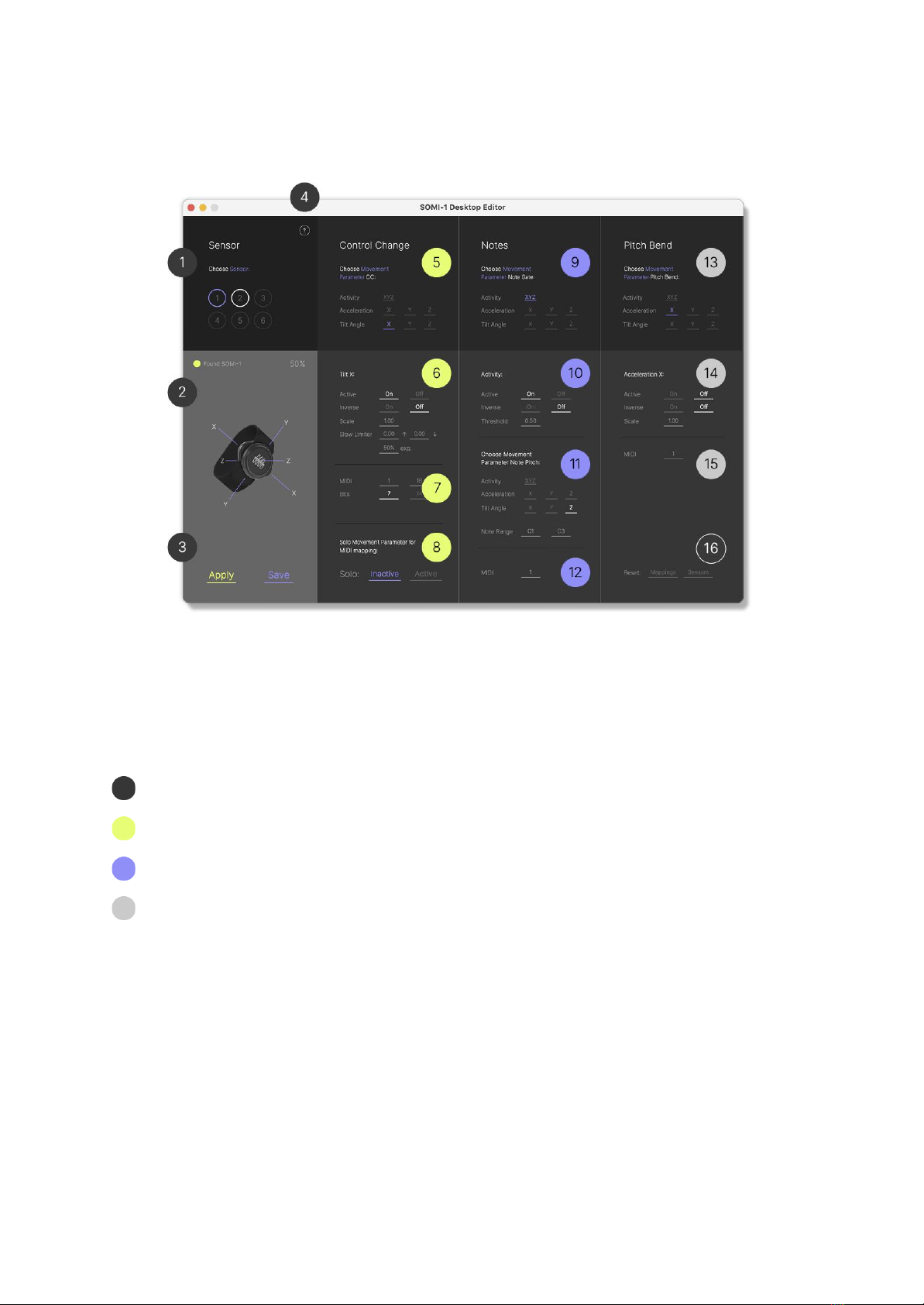
4.1 Standalone
The SOMI1 editor allows MIDI mapping MIDI learn) and customization of SOMI1
settings in real-time. The SOMI1 Editor is separated in three main sections (from left to
right):
Sensor selection and general settings 14 & 16
MIDI Control Change settings 58
MIDI Note settings 912
MIDI Pitch Bend settings 1315
1. Display of sensors 16. Choose the sensor you want to edit.
gray circle = sensor not connected
white circle = sensor connected
blue circle = sensor selected

2. Display of receiver status & display of battery status of selected sensor.
-
Found SOMI1 LED gray
SOMI1 is not connected
-
Found SOMI1 LED yellow
SOMI1 is connected
3. Apply button: Sends settings to SOMI1 always press apply after editing
parameters).
Save button: Saves settings on the SOMI1 hub (settings are saved after
unplugging the SOMI1 hub).
4. Links to updates, manual, quick start guide and support page.
5. MIDI Control Change section. Choose the movement parameter of your selected
sensor you want to edit (find movement parameters in manual section 3.2.
6. General
Control Change
settings of the selected movement parameter.
Active Turn parameter
on
or
off
Inverse Inverse the parameter value (e.g. value down, when arm raised)
Scale 010 Scale the parameter value (sensitivity of the movement)
Slew Limiter 01) Add a slew limiter to smooth the values
(↑ = raise time, ↓ = fall time, exp = linear to exponential in %
7. MIDI settings of selected movement parameter.
MIDI Left value MIDI channel, right value MIDI controller number
Bits Change MIDI resolution from 7 to 14 bits (
attention
: not every software
supports MIDI high resolution)
8. MIDI learn:
Solo
the selected movement parameter to map it to your desired
sound parameter.
Active Solo is active, the parameter can be mapped
Inactive Solo is inactive, the parameter can not be mapped

Note: Always click Inactive after you have finished your MIDI mappings.
9. MIDI Note section –
Note Trigger
parameter. Choose the movement parameter of
your selected sensor you want to use for triggering notes (find movement
parameters in manual section 3.2.
10. General
Note
settings of the selected movement parameter.
Active Turn parameter
on
or
off
Inverse Inverse the parameter value
Threshold 01 Change the sensitivity of the selected movement to trigger a
note.
11.
Note Pitch
parameter. Choose the movement parameter of your selected sensor
you want to use for changing the note’s pitch (find movement parameters in
manual section 3.2.
12. MIDI channel of the selected
MIDI Note
parameter.
13. MIDI Pitch Bend section Choose the movement parameter of your selected
sensor you want to use for pitch bend (find movement parameters in manual
section 3.2.
14. General
Pitch Bend
settings of the selected movement parameter.
Active Turn parameter
on
or
off
Inverse Inverse the parameter value
Scale 010 Scale the parameter value (sensitivity of the movement)
15. MIDI channel of the selected
Pitch Bend
parameter.
16. Reset the corresponding settings to factory defaults.
Note: Unfortunately Windows’ builtin MIDI driver does not allow using the same MIDI
device across multiple applications at the same time. A workaround can be found here.
4.2 SOMI1 Editor for Ableton Live Max for Live Device)
For native integration with Ableton Live, SOMI1 comes with a dedicated Max for Live
device allowing customization of SOMI1 settings in real-time. The different settings can
even be automated within Live’s arrangement to create different kinds of dynamic
presets in a project.
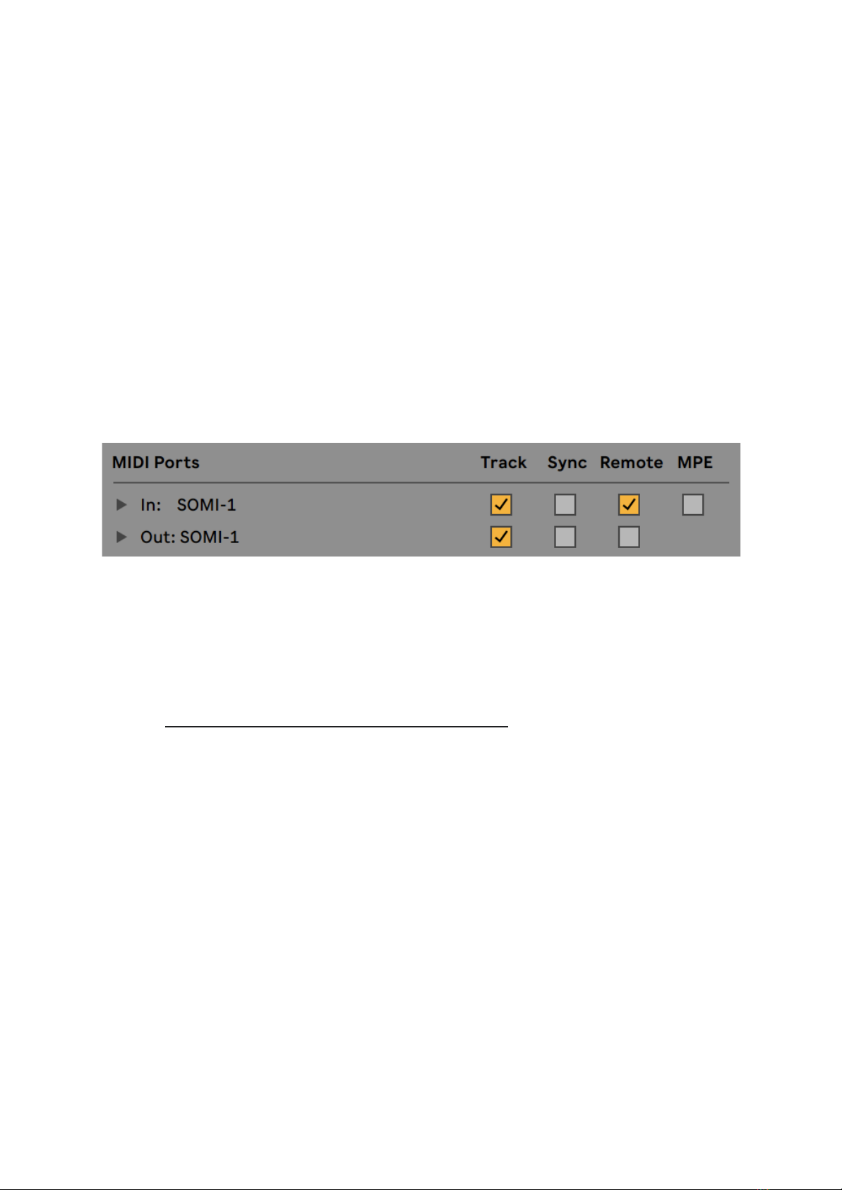
Setting up SOMI1 Editor for Live
To get started, connect the SOMI1 Hub to your computer and set up SOMI1 in Live’s
MIDI preferences. Enable Track and Remote for Input and Track only for Output as
shown in the following figure.
Note: We recommend changing the buffer size in Ableton Lives’ audio preferences to 64
128 samples to reduce latency (delay).
Download the Max for Live Device SOMI1 Editor for Live from the support page of our
website: https://instrumentsofthings.com/pages/support
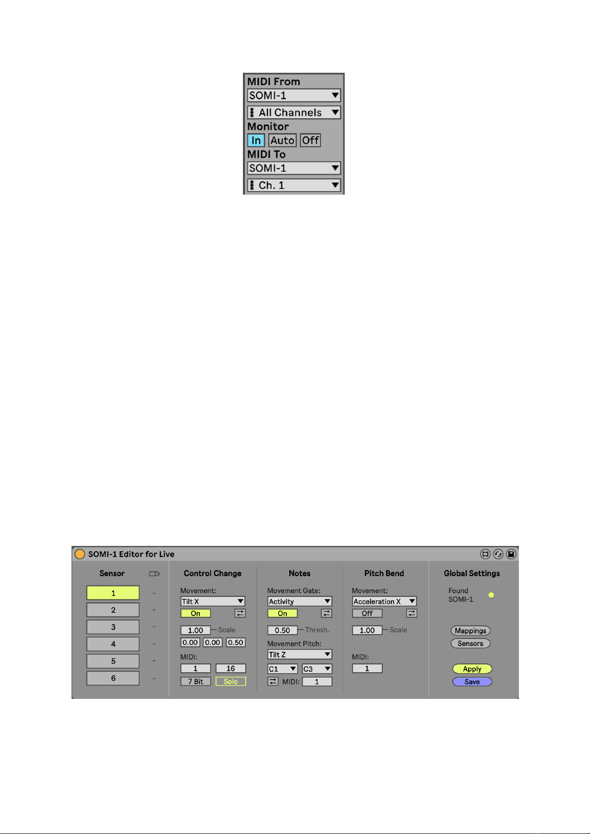
Create a new MIDI track in Live and add the SOMI1 Max for Live device to it. You will
notice the small circle next to Found SOMI1 on the right is gray, indicating that SOMI1
hasn’t been discovered by Live yet. The reason for this is that no MIDI data is sent and
received between Live and SOMI1 yet. To enable the MIDI connection select SOMI1 in
the MIDI From and MIDI To selection fields. Then select In for the Monitor of the track as
shown in the following figure.
The gray circle in the SOMI1 Max device will turn yellow indicating that a MIDI
connection between SOMI1 and Live has been established and SOMI1 can be now
configured via the Max device.
Note: You can also arm the MIDI track in Live to enable a connection between Live and
SOMI1. However, when adding new tracks in Live, arm is disabled in the SOMI1 MIDI
track. Thus, we recommend setting the Monitor to In instead.
Attention! If another track is soloed in Live, no MIDI data is transferred between
SOMI1 and Live! Thus always make sure that the MIDI track in Live containing the
SOMI1 Max device is soloed as well or disable solo for other tracks!
Using SOMI1 Editor for Live
After the SOMI1 Editor for Live has been set up as explained in the section before, it
should look as shown in the following figure.
The SOMI1 Editor for Live is separated in three main sections (from left to right):
- Sensor Select

- MIDI Settings
- Global Settings
Note: You can hover the mouse over the different UI elements of the SOMI1 Editor for
Live to get more detailed information.
Note: Currently shown settings are only updated on the SOMI1 Hub by clicking the
Apply button.
Note: The Save button persists all currently internal settings of the SOMI1 Hub to its
flash memory making them available after power off.
Note: Internal settings are not saved if Control Change Solo is active LED on hub is
yellow) or sensors are disabled LED on hub is red)!
Attention! Saving the current internal settings of the SOMI1 Hub will override all
previous settings!
Sensor Select Section
Selects the sensor, which should be configured and shows the battery levels of all
currently connected sensors. The currently shown settings in the MIDI section
correspond to the currently selected sensor.
MIDI Settings Section Control Change, Notes, Pitch Bend)
Allows customization of the supported MIDI messages of the currently selected sensor.
Control Change:
Each movement parameter corresponding to a Control Change Controller can be
configured independently. Thus the currently shown settings depend on the selected
movement parameter. Each movement parameter can be disabled, inverted, scaled,
smoothed, etc. Furthermore, SOMI1 supports high resolution 14 bit) Control Change
messages, which are suitable for high precision requirements such as pitch modulation.
The Solo / Unsolo toggle button is explained in the section Using Live’s MIDI Learn
Functionality.
Table of contents


