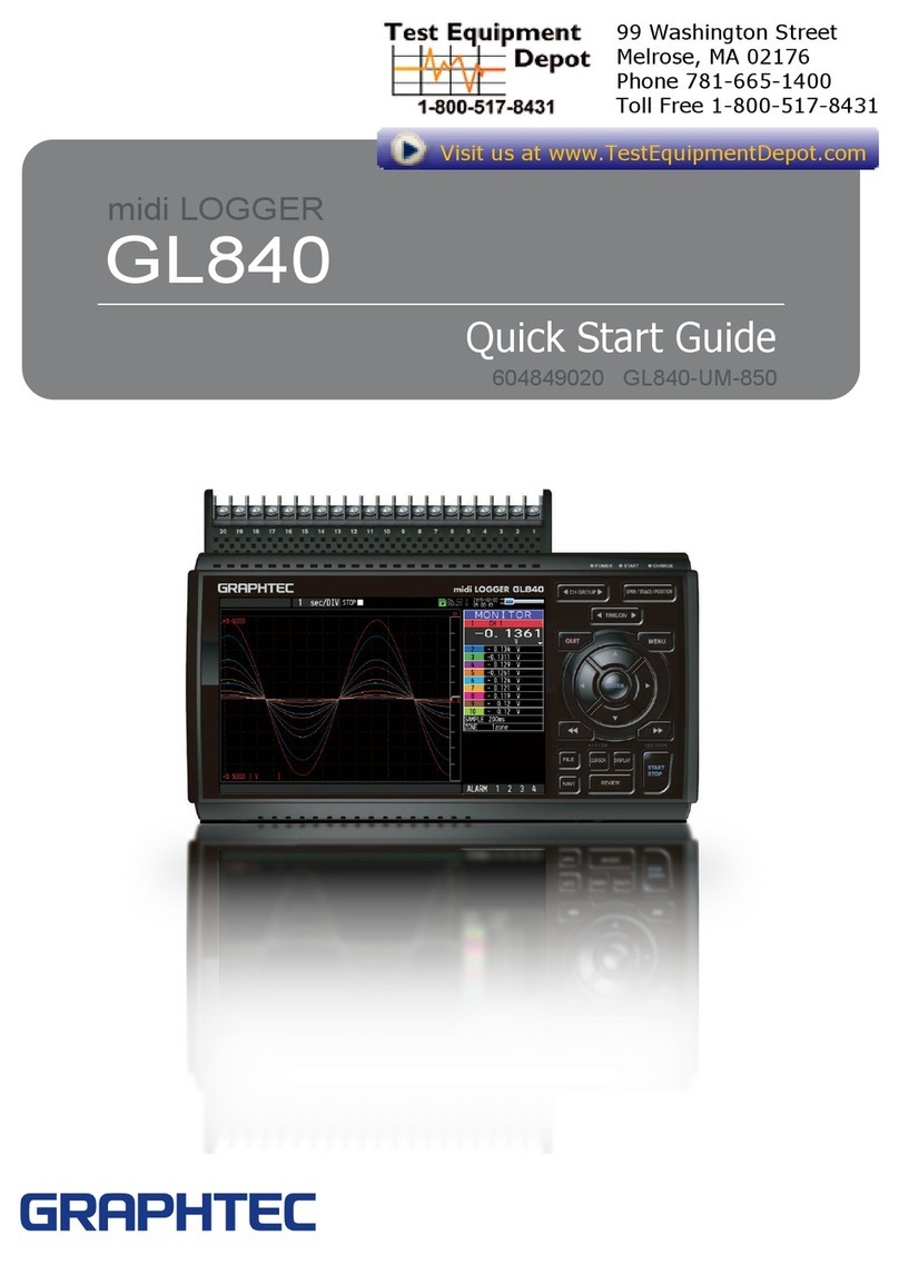
GRAPHTEC GL840 User manual

USER’S MANUAL
MANUAL NO.GL840-UM-154
GL840


i
To Ensure Safe and Correct Use
To Ensure Safe and Correct Use
•To ensure safe and correct use of the GL840, read this manual thoroughly before use.
•After having read this manual, keep it in a handy location for quick reference as needed.
•Do not permit small children to touch the GL840.
•The following describes important points for safe operation. Please be sure to observe them strictly.
Conventions Used in This Manual
To promote safe and accurate use of the GL840 as well as to prevent human injury and property damage,
safety precautions provided in this manual are ranked into the ve categories described below. Be sure you
understand the difference between each of the categories.
DANGER This category provides information that, if ignored, is
highly likely to cause fatal or serious injury to the operator.
WARNING This category provides information that, if ignored, is
likely to cause fatal or serious injury to the operator.
CAUTION This category provides information that, if ignored, could
cause physical damage to the GL840.
HIGH
TEMPERATURE
This category provides information that, if ignored, is
likely to cause burns or other injury to the operator due to
contact with high temperature.
ELECTRICAL
SHOCK
This category provides information that, if ignored, is
likely to expose the operator to electrical shock.
Description of Safety Symbols
The symbol indicates information that requires careful
attention (including warnings). The specic point requiring
attention is described by an illustration or text within or next to
the symbol.
The symbol indicates an action that is prohibited. Such
prohibited action is described by an illustration or text within or
next to the symbol.
The symbol indicates an action that must be performed.
Such imperative action is described by an illustration or text
within or next to the symbol.

ii
Safety Precautions
Safety Precautions
WARNING
Before turning on the GL840, ensure that the electric
socket’s supply voltage conforms to the GL840’s
power rating.
•Use of a different supply voltage may cause damage to the
GL840 or a fire hazard due to electrical
shock or current leakage.
If the GL840 generates smoke, is too hot, emits a
strange odor, or otherwise functions abnormally,
turn off its power and unplug its power cord from the
electrical socket.
•Use of the GL840 in such status may result in a fire hazard
or electrical shock.
•After checking that smoke is no longer being generated,
contact your sales representative or nearest Graphtec
vendor to request repair.
•Never try to perform repair yourself.
Repair work by inexperienced
personnel is extremely dangerous.
Never disassemble or remodel the GL840.
•Such action may cause a fire hazard due to electric shock
or current leakage.
•Contact with a high-voltage component inside the GL840
may cause electric shock.
•If repair is required, contact your
sales representative or nearest
Graphtec vendor.
Be sure to securely connect the GL840's GND
terminal.
•After checking that the power switch is turned off, connect
the power cord’s female plug to the GL840 and then
connect its male plug into the electrical socket.
•For grounding, use a ground wire with a diameter of at least
0.75 mm2. When using the GL840 in an environment where
grounding is not
possible, ensure measured is no greater than 50 V (DC or
rms).
Avoid using the GL840 in extremely dusty or humid
places.
•Such use may cause a fire hazard due to electrical shock or
current leakage.
Avoid using the GL840 in places where it may be
exposed to water such as bathrooms, locations
exposed to wind and rain, and so on.
•An electrical shock or fire may be caused due to current
leakage.
Prevent dust or metallic matter from adhering to the
power supply connector.
•Adhesion of foreign matter may cause a fire hazard due to
electrical shock or current leakage.
Never use a damaged power cord.
•Use of a damaged cord may result in a fire hazard due to
electrical shock.
•If the cord becomes damaged, order a new one to replace
it.
Use prohibited
Use prohibited
Use prohibited No disassembly
Watch out for
electrical shock
Use prohibited Watch out for
electrical shock
Watch out for
electrical shock
Avoid water
Unplug the power
cord from the socket

iii
Safety Precautions
Safety Precautions
CAUTION
If uid or foreign matters enters inside the GL840,
turn off the power switch and disconnect the power
cord from the electrical socket.
•Use in such status may cause a fire hazard due to electrical
shock or current leakage.
•Contact your sales representative or
nearest Graphtec vendor to request
repair.
To insert or disconnect the power cord or a signal
input cable, grasp the power cord’s plug or the signal
input cable’s connector.
•Pulling the cord/cable itself damages the cord/cable,
resulting in a fire hazard or electrical shock.
Do not use the GL840 in a location subject to
excessive mechanical vibration or electrical noise.
•Such location may impair the GL840’s performance.
Do not place the receptacles containing uid onto this
device or close to this device.
•Fluid spilling inside the GL840 may cause a fire hazard due
to electrical shock or current leakage.
Do not use the AC power supply and the DC power
supply other than the specied supply voltage for this
device.
•Such action may cause a fire hazard due to electric shock
or current leakage.
Do not use or store the GL840 in a location exposed to
direct sunlight or the direct draft of an air conditioner
or heater.
•Such location may impair the
GL840’s performance.
Do not attempt to lubricate the GL840’s mechanisms.
•Such action may cause the GL840 to break down.
Never clean the GL840 using a volatile solvent (such
as thinner or benzine).
•Such action may impair the GL840’s performance.
•Clean off any soiled areas using a soft dry cloth.
Use prohibited
Use prohibited Use prohibited
Use prohibited
Use prohibited
Use prohibited
Watch out for
electrical shock
Avoid water
Unplug the power
cord from the socket
Be sure to use the Graphtec-supplied AC adapter.
•It will damage this device.
Use prohibited

iv
Safety Precautions
Safety Precautions
CAUTION
Do not touch the device with wet hands.
•This can cause an electrical shock or malfunction.
Conrm the power of supplier of signal is turned
off before connecting the input cables to the input
terminal of this device to prevent the electric shock.
•It will cause the electric shock.
Be careful of static electricity.
•Static electricity may damage the device. To prevent this
from happening, touch a different metal object to discharge
any built-up static electricity before touching the GL840.
Do not touch the input terminals after the signal
cable is connected to the measuring objects that are
containing the voltage.
•It will cause the electric shock.
•Ensure that the GL840’s power source is positioned so that
it can easily be disconnected.
Do not input the voltage that is exceeding the
specication of this device.
•If a voltage exceeding the specified value is input, the
semiconductor relay in the input section will be damaged.
Never input a voltage exceeding the specified value even
for a moment.
•Have an enough margin from the specification of
withstanding voltage when using this device, it have to
consider a noise and change of the measurement voltage.
•It will cause the fire or the electric shock when the voltage is
input to the defective device.
Do not block the air vent on the GL840.
•This device will get damage when there is abnormal heat in
this device.
Conrm this device is not broken before the input
cable is connected to the input terminal.
•It will cause the fire or the electric shock when the voltage is
input to the defective device.
Strict observance
Strict observance
Strict observance
Use prohibited
Don't touch
with wet hands CAUTION
CAUTION
Use prohibited
HIGH
TEMPERATURE
Watch out for
electrical shock
Strict observance
Watch out for
electrical shock

v
Safety Precautions
Safety Precautions
CAUTION
When using the wireless unit (when option is
installed), please note the following:
•Turn off the device in places where wireless radio signal
use is restricted, such as on aircrafts and in hospitals. The
device can have an effect on electronic devices, medical
devices, etc., and may cause malfunctions.
When using the wireless unit (when option is
installed) in a medical establishment, please note the
following rules:
•Please turn off the power of this product in hospital wards.
•Each medical institution has its own usage prohibitions in
various areas. Be sure to follow these.
When using the wireless unit (when option is
installed), please note the following:
•In the event that the device has an effect on automatic
electronic devices such as cars or elevators, immediately
turn off the GL840.
When using the wireless unit (when option is
installed), please note the following:
•
If you have an implantable pacemaker or implantable
defibrillator installed, radio signals from the device may have
an effect on the operation of your implantable pacemaker or
implantable defibrillator.
This GL840 is not meant for use with lifesaving devices or devices with mission-critical high reliability or
high safety requirements (medical devices, aerospace devices, shipping devices, nuclear power devices,
etc.). In the event that this GL840 causes injury or property damage when used under these circumstances,
the maker assumes absolutely no responsibility and is not liable.
Do not use the device in any way not specied in this
manual. There is a danger that protective provisions
will have not been put in place.
The module connection terminal is for use only with
separately sold sensors and modules. Do not connect
any other devices. Doing so may damage the GL840.
Strict observance
Strict observance
Use prohibited
Use prohibited
Use prohibited
Use prohibited


I
Introduction
Introduction
Thank you for purchasing the GL840 midi LOGGER.
Please read this manual thoroughly before attempting to use your new product to ensure that you use it correctly
and to its full potential.
Notes on Use
Be sure to read all of the following notes before attempting to use the GL840 midi LOGGER.
1. Note on the CE Marking
The GL840 midi LOGGER complies with the following standards.
• EN 61326-1 : 2013 standard based on the EMC directive (2014/30/EU)
• EN 61010-1:2010 3rd standard based on the LVD directive (2014/35/ EU)
• EN 301 489-1/-17, EN 300 328 standards based on the RED directive (2014/53/EU)
Although the GL840 complies with the above-mentioned standards, be sure to use it correctly in accordance
with the instructions and notes provided in this manual.
Moreover, use of the GL840 by incorrect procedures may result in damage to the GL840 or may invalidate its
safeguards. Please conrm all of its notes regarding use and other related information to ensure correct use.
2. Warning
This is a Class A product according to the EMC directive. In a domestic environment, this product may cause
radio interference or may be affected by radio interference to the extent that proper measurement cannot be
performed.
3. Notes on Radio Law
When installing the wireless unit (option) on the GL840, please note the following:
Do not remove the technical standards compliance label. Do not use the device if it does not have a label
on it.
This GL840 uses the 2.4GHz frequency band.
The following devices and transmitters use the same frequencies and should not be used near this GL840:
• Microwave ovens
• Pacemakers and other industrial, science, and medical devices
• Radio transmitters used in mobile body identication devices on factory production lines, etc. (transmitters
requiring licensing)
• Specied low-power radio transmitters (transmitters not requiring licensing)
Communications may become slower or impossible due to radio interference.
The communications may become slower or impossible depending on the circumstances this GL840 is
used in. Take particular note of steel-reinforced, metal, concrete, and other structural materials that can
inhibit radio waves.

II
Introduction
This GL840 is meant for use in Japan, the US, Europe,Taiwan,China and Korea. It has not been certied
for use under any other country’s radio laws.
The following are each region’s certication marks.
Contains NCC ID:
CCAB15LP4220T2
CMIIT ID: 2015DJ5376
MSIP-CRI-KTM-B-568
Japan
US
Europe
R 003WWA100913
Taiwan
China
Korea
Contains FCC ID: ANSBP3591
CE Mark
This device complies with part 15 of the FCC Rules. Operation is subject to the following two conditions:
(1)This device may not cause harmful interference, and (2)this device must accept any interference received,
including interference that may cause undesired operation.
FCC CAUTION
Change or modications not expressly approved by the party responsible for compliance could void the user’s
authority to operate the equipment.
This transmitter must not be co-located or operated in conjunction with any other antenna or transmitter.
4. Notes for Safe Operation
(1) Be sure to use the Graphtec-supplied AC adapter. In environments where there is a lot of noise or where
the power supply is unstable, we recommend that you ground the GL840.
(2) When a high-voltage signal cable has been connected to the main unit’s analog signal input terminal,
avoid touching the leads of the input terminal’s signal cable to prevent electrical shock due to high voltage.
(3) Ensure that the GL840’s power source is positioned so that it can easily be disconnected.
(4) When connecting the high voltage signal line to the analog signal input terminal using the 4ch voltage/
temperature terminal on the separately sold module (GS-4VT), avoid touching the leads of the input
terminal’s signal line to prevent electrical shock due to high voltage.
(5) Do not input the voltage that is exceeding the specication of this device.
• If a voltage exceeding the specied value is input, the semiconductor relay in the input section will be
damaged. Never input a voltage exceeding the specied value even for a moment. It will cause the re.
• Have an enough margin from the specication of withstanding voltage when using this device, it have to
consider a noise and change of the measurement voltage.
• Conrm this device is not broken before the input cable is connected to the input terminal.
• Please take care of the static electricity when the connecting the input cables or the thermocouples.

III
Introduction
• Do not touch the tip of thermocouples with bare hand after the thermocouples are connected to the
terminal of this device when the tip of thermocouples is not insulated.
The static electricity of a human body will cause damage to this device.
• Do not put the tip of thermocouples to the object which is containing the static electricity when the tip of
thermocouples is not insulated. The static electricity of object will cause damage to this device.
• Do not put the tip of thermocouples to the object which is containing the leaked high voltage of chassis or
metal etc. when the tip of thermocouples is not insulated.
The leaked high voltage of object will cause damage to this device.
• We recommend that the insulation tape puts on the tip of thermocouples before connecting the
thermocouples to the input terminals.
This will protect this device from the static electricity and the leaked high voltage.
* This applies to all the channels even if channel extension is used.
* When B-564 (B-564SL) and B-565 are mixed, the specications of B-564 (B-564SL) is applied to all
channels.
5. Notes on Functions and Performance
(1) Be sure to connect the main unit to an AC or DC power supply that conforms to the rated range.
Connection to a non-rated power supply may cause the main unit to overheat and break down.
(2) Do not block the vent on the main unit.
Continued operation with the vent blocked may cause the main unit to overheat and break down.
(3) To avoid malfunctions and other damage, avoid using the GL840 in the following locations.
• Places exposed to high temperature and/or high humidity, such as in direct sunlight or near
heatingequipment.
(Allowable temperature range: 0 to 45°C (0 to 40°C when a battery pack is mounted, 15 to 35°C when
battery is being charged), Allowable humidity range: 5 to 85%R.H., non-condensing)
• Locations subject to excessive salt spray or heavy fumes from corrosive gas or solvents.
• Excessively dusty locations.
• Locations subject to strong vibrations or shock.
• Locations subject to surge voltages and/or electromagnetic interference.
(4) If the main unit becomes soiled, wipe it off using a soft, dry cloth. Use of organic solvents (such as thinner
or benzene) causes deterioration and discoloration of the outer casing.
(5) Do not use the GL840 in the vicinity of other devices which are susceptible to electromagnetic
interference.
(6) Measured results may not conform to the stated specications if the GL840 is used in an environment
which is subject to strong electromagnetic interference.
(7) Insofar as possible, position the GL840 input signal cables away from any other cables which are likely to
be affected by electromagnetic interference.
(8) For stabilized measurement, allow the GL840 to warm up for at least 30 minutes after turning it on.

IV
Introduction
(9) When you want to use in combination of the Petit LOGGER GL100-WL (separately sold) and various
modules (such as GS sensor and terminal / adapter), please refer to the GL100 User’s Manual.
• When using in combination described above, please be careful to the operating environment because
the environmental conditions of the GL840 midi LOGGER are applied.
It may cause abnormal operation or damage.
• Allowable temperature range: 0 to 45°C, Allowable humidity range: 5 to 85%R.H, non-condensing.
(0 to 40°C when battery-powered / 15 to 35°C when charging)
When using temperature and humidity sensor (GS-TH) and the GL840 at the same time, the
operating environment of GL840 is applied.
• Temperature and Humidity Sensor (GS-TH):
• Humidity sensors measure the change in dielectric capacity of water adsorption. As a result, humidity
from organic materials such as ne particles or exhaust gas may have an effect on the sensor. Use
in environments with large quantities of these organic materials may lead to signicant measurement
inaccuracies.
• CO2 Sensor (GS-CO2 ):
• Because exhaled CO2 may have an effect on the sensor readings, do not use the sensor to take
measurements near the face.Additionally, should air ow to the sensor be blocked, it will result in
inaccurate readings, so be sure to keep vent holes open.
• Illumination / Ultraviolet Sensor (GS-LXUV):
• When measuring illumination or ultraviolet light that can have harmful effects on the eyes or skin, be
sure to use protective eyewear, shielding, etc.
• If the sensor becomes dirty, it may affect measurements, so wipe it with a soft cloth when it becomes
dirty.
• Take care to avoid cracking the sensor when handling it. If the sensor is damaged or cracked it may
affect measurements, so replace the sensor.
•Others
• Depending on the usage and operating environment of Temperature and Humidity Sensor (GS-
TH), CO2 Sensor (GS-CO2), and Illumination / Ultraviolet sensor (GS-LXUV), it is recommended to
replace periodically the sensor with new one because the sensor performance may be deteriorated.
• The 3-axis Acceleration/Temperature Sensor (GS-3AT) conforms to the IP54 standards, but the
GL840 does not conform to the IP54 standards. When connecting the GS-3AT to the GL840, it cannot
be used as a product that conforms to the IP54 standards.

V
Introduction
Notes on the Use of This Manual
(1) All rights reserved. No part of this publication may be reproduced, stored in a retrieval system, or transmitted, in
any form or by any means, without the prior written permission of Graphtec Corporation.
(2) The specications and other information in this manual are subject to change without notice.
(3) While every effort has been made to supply complete and accurate information about this product, please
address any inquiries about unclear information, possible errors, or other comments to your sales representative
or nearest Graphtec vendor.
(4) Notwithstanding the preceding paragraph, Graphtec Corporation assumes no liability for damages resulting
from the use of the information contained herein or of the product.
About Registered Trademarks
Microsoft and Windows are registered trademarks or trademarks of Microsoft Corporation in the U.S. and
elsewhere.
Other company names and product names included in this manual are registered trademarks or trademarks of
their respective companies.
Copyright
All copyrights regarding this manual belong to Graphtec Corporation.


C-1
CONTENTS
CONTENTS
To Ensure Safe and Correct Use ................................................i
Safety Precautions...........................................................ii
Introduction .................................................................I
Notes on Use .................................................................I
Notes on the Use of This Manual ................................................V
About Registered Trademarks ...................................................V
Copyright ...................................................................V
CHAPTER 1 General Description
1.1 Overview.............................................................1-2
1.2 Features .............................................................1-2
1.3 Operating Environment.................................................1-3
Ambient Operating Conditions................................................. 1-3
Warming-up Before Use ..................................................... 1-4
Conguration When in Use ................................................... 1-4
1.4 Notes on Temperature Measurement .....................................1-5
1.5 Notes on Using the Monitor .............................................1-5
1.6 Changing the Display Language .........................................1-5
CHAPTER 2 Checks and Preparation
2.1 Checking the Outer Casing..............................................2-2
2.2 Checking the Accessories ..............................................2-2
2.3 Nomenclature and Functions ............................................2-3
2.4 Connecting the Power Cable and Turning on the Power ..................... 2-4
2.5 Connecting the Signal Input Cables ..................................... 2-6
2.6 Logic Alarm Cable Connection and Functions..............................2-9
2.7 Mounting the SD CARD ................................................2-12
2.8 Installing the Cover (B-578: Option) .....................................2-14
2.9 Installing the Wireless Unit (B-568: Option) ...............................2-16
2.10 Connecting to a PC ...................................................2-18
2.11 Using the Battery Pack (B-569: Option) ..................................2-21
2.12 Connecting the Humidity Sensor (Optional)...............................2-23
2.13 Removing and mounting each terminal. . . . . . . . . . . . . . . . . . . . . . . . . . . . . . . . . . .2-24
2.14 Mounting the Extension Terminal Base (Optional) and
Extension Terminal Cable (Optional) .....................................2-26
2.14.1 Mounting the extension terminal base...................................... 2-26
2.14.2 Mounting multiple extension terminals ..................................... 2-28
2.15 Precautions to Observe When Performing Measurement....................2-32
2.16 Noise Countermeasures ...............................................2-35
2.17 Connecting the Temperature and Humidity Sensor (GS-TH) (Optional) ........2-36

C-2
CONTENTS
2.18 Connecting the 3-axis Acceleration / Temperature Sensor (GS-3AT) (Optional) .2-37
2.19 Connecting the 4ch Voltage / Temperature Terminal (GS-4VT) (Optional) ..... 2-38
2.20 Connecting the 4ch Thermistor Terminal (GS-4TSR) (Optional)...............2-41
2.21 Connecting the Illumination / Ultraviolet Sensor (GS-LXUV) (Optional) ....... 2-44
2.22 Connecting the CO2 Sensor (GS-CO2) (Optional) ......................... 2-45
2.23 Connecting the Adapter for AC Current Sensor (GS-DPA-AC) (Optional) ...... 2-46
2.24 Connecting the Branch Adapter for GS (GS-DPA) (Optional) ................ 2-48
2.25 When Fixing the GL840 Body ...........................................2-51
2.26 Setting the Date and Time. . . . . . . . . . . . . . . . . . . . . . . . . . . . . . . . . . . . . . . . . . . . . .2-52
CHAPTER 3 Settings and Measurement
3.1 Window names and functions ...........................................3-2
3.2 Key Operation ....................................................... 3-8
3.3 Operation Modes .....................................................3-17
3.4 Setting Menus .......................................................3-21
(1) AMP settings............................................................ 3-21
(2) DATA settings ...........................................................3-47
(3) TRIG settings ...........................................................3-55
(4) Interface settings ........................................................3-61
(5) OTHER settings.........................................................3-80
(6) FILE menu .............................................................3-84
(7) File box ................................................................3-89
(8) Character string input ..................................................... 3-91
(9) Data replay menu ........................................................3-92
(10) Integrated bar graph display ...............................................3-96
(11) NAVI menu ........................................................... 3-100
(12) Quick settings ......................................................... 3-102
(13) To cancel key lock by password ........................................... 3-103
3.5 WEB Server Function ................................................3-104
3.6 List of Error Codes ..................................................3-109
CHAPTER 4 Specication
4.1 Standard Specications ................................................4-2
Standard Specications...................................................... 4-2
Memory devices............................................................ 4-3
PC I/F.................................................................... 4-3
Monitor................................................................... 4-3
GL840-M: B-564 / B-564SL................................................... 4-4
GL840-WV: B-565 .......................................................... 4-6
4.2 Function Specications ............................................... 4-8
Function Specications ...................................................... 4-8
Trigger/Alarm Functions...................................................... 4-8
External Input/Output Functions ............................................... 4-9

C-3
CONTENTS
4.3 Accessories/Optional Accessories . . . . . . . . . . . . . . . . . . . . . . . . . . . . . . . . . . . . . .4-10
Control Software .......................................................... 4-10
Accessories .............................................................. 4-10
Wireless LAN Unit B-568 (Option)............................................. 4-10
Battery Pack B-569 (Option) ..................................................4 -11
Humidity Sensor B-530 (Option) ...............................................4 -11
List of Options ............................................................ 4-12
4.4 External Dimensions ..................................................4-13
INDEX ..............................................I-1


1-2
CHAPTER 1 General Description
1.1 Overview
The GL840 is a compact, lightweight, multi-CH, and multi-purpose data logger with a 7-inch color display.
There are three types of terminal units with 20 channels. By using the expansion terminal base, it is possible
to measure up to 200 channels. In addition, when connecting various modules, the voltage, temperature and
humidity as well as the acceleration, AC current, CO2, and illuminance / ultraviolet etc. can be measured.
The GL840 can save the high-capacity measurement data directly in the internal memory or SD CARD.
For the PC interface, as USB and Ethernet is included as standard, system conguration according to use
is possible. As the Ethernet function is equipped with both WEB server and FTP server functions, remote
supervision and data transfer are also possible. Multipurpose remote measurement can also be performed
by installing an optional wireless unit and using it in combination with a wireless LAN.
1.2 Features
Input
• Adoption of a pluggable M3 screw type or screwless type input terminal facilitates wiring.
• Up to 200 channels can be connected using the expansion terminal base and the terminal unit with 20
channels.
• When using the Graphtec’s GS series and terminal / adapter, the acceleration, AC current, CO2, and
illuminance / ultraviolet measurements are also possible.
• Because that the terminals of all terminal units have a whole CH isolated, the different standard signals
can be measured at the same time.
In addition, when using the withstand high-voltage high-precision terminal, you can measure in the
environmental conditions of high withstand voltage.
Display & Operation
• With the GL840’s high-resolution 7-inch TFT color liquid crystal display, you can conrm the waveforms of
measured data and each channel’s settings at a glance.
•Easy operation is achieved through a straightforward menu structure and key allocation which resembles
mobile phones.
Data Capture
• The high-capacity measurement data can be saved directly in the internal memory or SD CARD.
• Because the SD CARD is used as an external memory, you can measure a long period of time with peace
of mind while data backup.
* When the optional wireless unit is installed, the SD CARD cannot be inserted into the SD CARD2 slot.
• Because disk image can be used for the internal memory, multiple data can be saved.
•The new ring memory capture function maintains latest data even after capturing for a long term. (You
need to set how long you want to keep data.)
• For voltage, temperature and humidity measurements, data can be captured at sampling rates of up to
10 msec per channel by using fewer measuring channels. (Temperature measurement can be done at
sampling rates of 100 msec and higher.)
• The GL840 is equipped with the relay recording function, and 2GByte or more data can be saved by
switching the to the other le without data missing. (When the capacity of one le reaches 2000MB, the
le is switched.)
Other manuals for GL840
5
Table of contents
Other GRAPHTEC Recording Equipment manuals

