manuals.online logo
Brands
  1. Home
  2. •
  3. Brands
  4. •
  5. Harman
  6. •
  7. Recording Equipment
  8. •
  9. Harman AMX AXB-DMX512 User manual

Harman AMX AXB-DMX512 User manual

QUICK START GUIDE
AXB-DMX512 DMX512 Interface
Overview
The AXB-DMX512 creates a bi-directional DMX512-to-AxLink connection, transmitting
and receiving up to 512 DMX channels. On-board processing and memory create as
many as 96 channel groups, eight faders, and 72 presets (284 by adding extended
memory), as well as soft-patch channels. A DMX lighting board can operate in tandem
with the AXB-DMX512, generate levels for storing presets, or bypass the AXB-DMX512
for direct control of channels.
Specifications
Setting the Device DIP Switch
The 8-position DEVICE DIP switch on the front panel (FIG. 1) sets the AxLink
identification number for the AXB-DMX512. Make sure the device number matches the
number assigned in the Axcess software program.
The following table describes the values on the DEVICE DIP switch.
Terminating the Device
When using the DMX input and if this device is the last device in a chain of DMX512
devices, you must terminate the line. To terminate the device, position jumpers on
jumper pin trios JP4 and JP5 (FIG. 2):
1. Remove the jumper that is on pins 1 and 2 of jumper trios JP4 and JP5. (Pins 1
and 2 are marked HIZ - see FIG. 3).
2. Place the jumper on pins 2 and 3 of jumper trios JP4 and JP5. (Pins 2 and 3 are
marked TERM -see FIG. 3). This terminates the incoming DMX input with a 120
ohm resistor.
Wiring Devices to the AXB-DMX512
The AXB-DMX512 has three captive-wire connectors on the rear panel (FIG. 4) for
DMX512 transmit and receive, and AxLink.
Preparing/Connecting Captive Wires
1. Strip 0.25 inch of wire insulation off all wires.
2. Insert each wire into the appropriate opening on the connector according to the
wiring diagrams and connector types described in this section. Do not tighten the
screws excessively; doing so may strip the threads and damage the connector.
Wiring Guidelines
The interface requires a 12 VDC power to operate properly. The Central Controller
supplies power via the AxLink cable or external 12 VDC power supply. The maximum
wiring distance between the Central Controller and interface is determined by power
consumption, supplied voltage, and the wire gauge used for the cable.
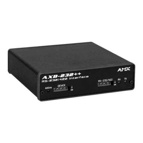
FIG. 1 AXB-DMX512 (FRONT VIEW)
AXB-DMX512 SPECIF ICATIONS
Power consumption 160 mA @ 12 VDC
Power supply 12 VDC
Front panel components:
LED Indicators • AXlink LED (green and blinks to indicate AXlink communication
activity and power:
Full-Off indicates no power is being received or the controller is
not functioning properly.
One blink per second indicates power is active and AXlink
communication is functioning.
Full-On indicates there is no AXlink control or activity, but power is
On.
• RX LED (red) indicates the AXB-DMX512 is receiving DMX512 data.
Corresponds to the IN and OUT ports on the rear panel.
• TX LED (red) indicates the AXB-DMX512 is transmitting DMX512
data. Corresponds to the IN and OUT ports on the rear panel.
DIP switch • 8-position DEVICE DIP switch sets the AxLink address (Device ID)
for the AXB-DMX512.
• The DIP Switch to the right of the DEVICE DIP is reserved - no
settings are required.
Rear panel components:
DMXIN port 5-wire, captive-wire connector for receiving data.
DMXOUT port 5-wire, captive-wire connector for transmitting data.
AXlink 4-wire, captive-wire connector for data and power.
Dimensions (HWD) 1.5" x 5.5" x 5.5" (38 mm x 140 mm x 140 mm)
Enclosure Metal with black matte finish
Mounting Rack mounting with the optional AC-RK Accessory Rack Kit
Weight 1.1 lb (0.5 kg)
DEVICE DIP SWITCH SETTINGS
Position 123 4 5 6 7 8
Value 1 2 4 8 16 32 64 128
AXlink DEVICE
ON
RXTX
Device ID DIP Switch
AxLink activity LED DMX512 (Transmit) LED
DMX512 (Receive) LED
FIG. 2 LOCATION OF TERMINATION JUMPERS (JP4-JP5)
FIG. 3 TERMINATION JUMPER PIN SETTINGS FOR JP4 AND JP5
FIG. 4 AXB-DMX512 (REAR VIEW)
COR
JP5
JP4
front
Termination Jumpers
(JP4 / JP5)
DEVICE DIP Switch
The DIP Switch located to the
right of the DEVICE DIP switch
is not used - no settings are
required, and any setting
will work.
TERM
HIZ
IN OUT AXlink
DATA
GND
GND
DATA
DATA
DATA
NC
DATA
DATA
DATA
DATA
NC
GND
AXP
AXM
PWR
1
2
1
2
1
1
2
2
© 2015 Harman. All rights reserved. Axcess, AMX, AV FOR AN IT WORLD, HARMAN, and their respective logos are registered trademarks of
HARMAN. Oracle, Java and any other company or brand name referenced may be trademarks/registered trademarks of their respective companies.
AMX does not assume responsibility for errors or omissions. AMX also reserves the right to alter specifications without prior notice at any time.
The AMX Warranty and Return Policy and related documents can be viewed/downloaded at www.amx.com.
3000 RESEARCH DRIVE, RICHARDSON, TX 75082 AMX.com | 800.222.0193 | 469.624.8000 | +1.469.624.7400 | fax 469.624.7153
AMX (UK) LTD, AMX by HARMAN - Unit C, Auster Road, Clifton Moor, York, YO30 4GD United Kingdom • +44 1904-343-100 • www.amx.com/eu/
93-5927-01 REV: B
Last Revised: 11/03/2015
The table below lists wire sizes and maximum lengths allowable between the AXB-
DMX512 and Central Controller. The maximum wiring lengths for using AxLink power
a re b a s ed o n a m i n im u m o f 1 3. 5 vo l ts av a ila b le a t th e Ce n t ra l Co n t ro l le r ’ s p o w e r s u p p l y.
Using AxLink communication
Connect the AxLink wiring to the connector on the AXB-DMX512, as shown in FIG. 5.
DMX512 data communication
Note: Some DMX devices only use DATA+ and DATA-. Connect these to DATA1+ and
DATA1-, leaving DATA2+ and DATA- unconnected. The DATA2 In and Out ports are not
currently supported.
Tra ns mit Wirin g
For transmit wiring, connect the DMX512 wiring to the OUT connector, as shown in
FIG. 6.
Receive Wiring
For receive wiring, connect the DMX512 wiring to the IN connector, as shown in FIG. 7.
Mounting the AXB-DMX512 in a Rack
To mount the AXB-DMX512 in an equipment rack, you will need an AC-RK rack
mounting kit.
1. Remove the two screws on the front panel of the AXB-DMX512.
2. Remove the front panel and the space bracket behind the panel.
3. Remove the rubber feet on the bottom of the unit, if necessary. Insert a scissors
blade or other sharp object into the side of one of the rubber feet and pull it off.
Do the same to remove the other three rubber feet.
4. Place the unit in the appropriate opening in the AC-RK.
5. Place the front panel of the AXB-DMX512 on the front of the rack over the unit
and secure the screws.
Replacing the Lithium Battery
A lithium battery (FIG. 8) with a life of approximately 5 years, protects stored presets if a
power loss occurs. The battery is not used when DC power is supplied to the AXB-
DMX512. Write down the replacement date on a sticker or label by adding 5 years to the
date of installation, and then attach it to the bottom of the AXB-DMX512.
Note: All control commands in AXB-DMX512 memory are lost when the lithium battery is
replaced
Contact your AMX dealer before you replace the lithium battery and verify that they
have a current copy of the Axcess program for your AXB-DMX512. This will avoid any
inadvertent loss of data or a service outage.
You will need a flat-blade tool (non-conducting) that can be slipped under the lithium
battery to pry it up and out of the socket.
Note: Static electricity can damage electronic circuitry. Before removing the lithium
battery from the enclosure, discharge any accumulated static electricity from your body
by touching a grounded metal object.
1. Discharge the static electricity from your body.
2. Unplug all cables from the AXB-DMX512.
3. Remove the AC-RK and AXB-DMX512 from the mounting rack. Otherwise, go to
step 4.
4. Remove the five pan-head screws on the top of the AXB-DMX512 enclosure.
5. Pull the two enclosure halves apart and set the bottom portion of the enclosure
on a flat surface.
6. Locate the battery on the circuit card.
7. Carefully pry the battery out of its socket and insert the new battery. Write down
the next replacement date on a sticker or label by adding 5 years to the
replacement date, and then attach it to the bottom of the AXB-DMX512.
8. Plug all cables back into the AXB-DMX512.
9. Place the top portion of the enclosure back onto the bottom portion. Then,
refasten the f ive pan-head screws.
10. Reconnect the cables removed for battery replacement.
Note: There is a danger of explosion if you replace the battery incorrectly. Replace the
battery with the same or equivalent type recommended by the manufacturer. Dispose of
used battery according to the manufacturer's instructions. Never recharge, disassemble,
or heat the battery above 212 °F (100 °C). Never solder directly to the battery or expose
the contents of the battery to water.
WIRING GUIDELINES AT 160 MA
Wire Size Maximum Wiring Length
18 AWG 733.57 feet (223.59 m)
20 AWG 464.11 feet (141.46 m)
22 AWG 289.35 feet (88.19 m)
24 AWG 182.39 feet (55.59 m)
FIG. 5 AXLINK WIRING
FIG. 6 DMX512 TRANSMIT WIRING
FIG. 7 DMX512 RECEIVE WIRING
PWR
AXP
AXM
GND
PWR
AXP
AXM
GND
Device
AxLink connector
on AXB-DMX512
DMX 512 OUT
connector on AXB-DMX512
GND
DATA1-
DATA1+
DATA2-
DATA2+
NC
GND
DATA1-
DATA1+
DATA2-
DATA2+
Device
DMX 512 IN
connector on AXB-DMX512
GND
DATA1-
DATA1+
DATA2-
DATA2+
NC
GND
DATA1-
DATA1+
DATA2-
DATA2+
Device
FIG. 8 LITHIUM BATTERY AND SOCKET
Battery (CR2032 type - 20mm coin cell)
socket
Other Harman Recording Equipment manuals

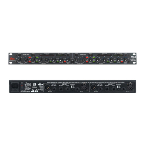
Harman DBX 1066 User manual

Harman

Harman DBX 1066 User manual

Harman DriveRack VENU360 User manual

Harman

Harman DriveRack VENU360 User manual

Harman BSS Audio Soundweb London LU-800 User manual

Harman

Harman BSS Audio Soundweb London LU-800 User manual

Harman Lexicon MC-10 Quick start guide

Harman

Harman Lexicon MC-10 Quick start guide

Harman dbx go Rack User manual

Harman

Harman dbx go Rack User manual

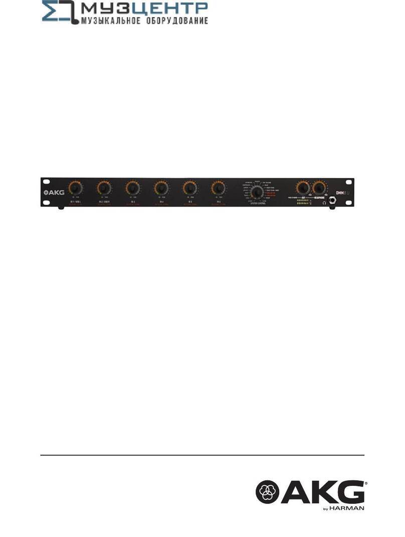
Harman AKG DMM8 U User manual

Harman

Harman AKG DMM8 U User manual

Harman BSS Soundweb London BLU-USB User manual

Harman

Harman BSS Soundweb London BLU-USB User manual

Harman JBL VTX Series User manual

Harman

Harman JBL VTX Series User manual

Harman BLU-Si Service manual

Harman

Harman BLU-Si Service manual

Harman Crown DSi 8Mn User manual

Harman

Harman Crown DSi 8Mn User manual

Harman Lexicon MX400 User manual

Harman

Harman Lexicon MX400 User manual

Harman AMX TPI-PRO-DVI Series User manual

Harman

Harman AMX TPI-PRO-DVI Series User manual

Harman Soundweb London BSS BLU-800 User manual

Harman

Harman Soundweb London BSS BLU-800 User manual

Harman Soundcraft Compact Stagebox Troubleshooting guide

Harman

Harman Soundcraft Compact Stagebox Troubleshooting guide

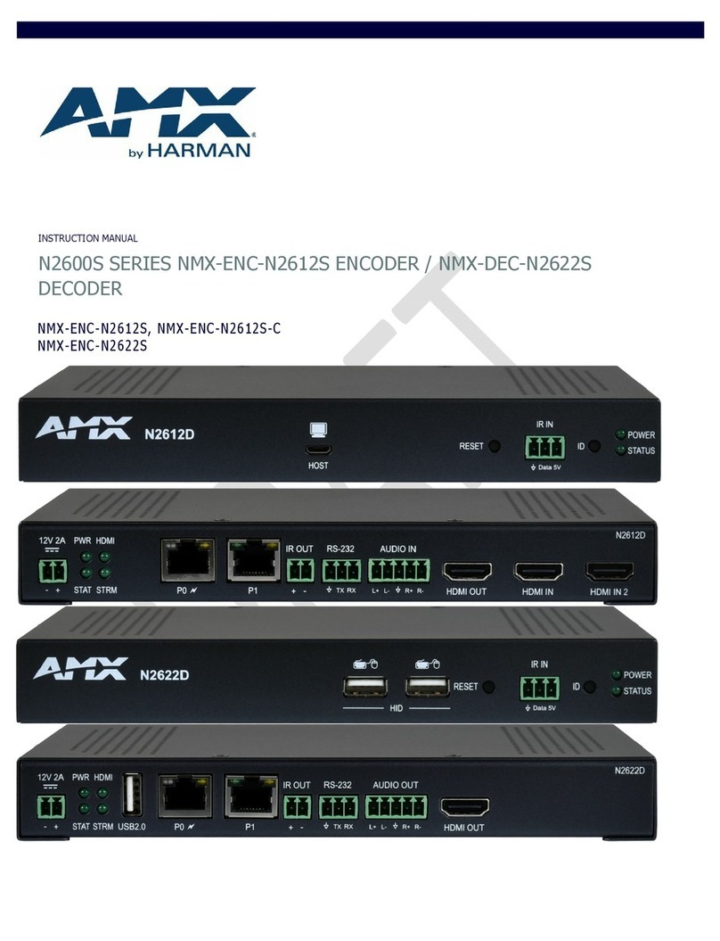
Harman AMX N2600S Series User manual

Harman

Harman AMX N2600S Series User manual

Harman AKG C411 Series User manual

Harman

Harman AKG C411 Series User manual

Harman Lexicon PCM96 Surround User manual

Harman

Harman Lexicon PCM96 Surround User manual

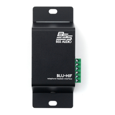
Harman BSS Soundweb London BLU-HIF User manual

Harman

Harman BSS Soundweb London BLU-HIF User manual

Harman Lexicon MC-10 How to use

Harman

Harman Lexicon MC-10 How to use

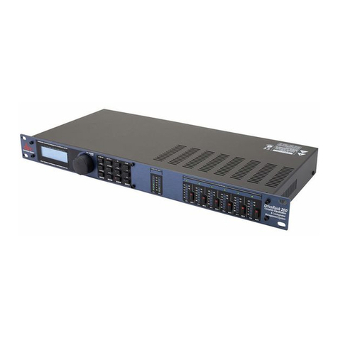
Harman dbx DriveRack 260 User manual

Harman

Harman dbx DriveRack 260 User manual

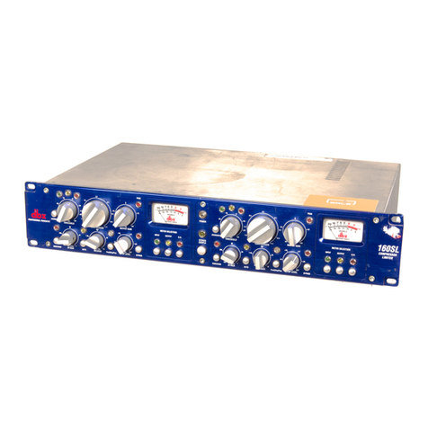
Harman dbx 160SL User manual

Harman

Harman dbx 160SL User manual

Harman Lexicon QLI-32 User manual

Harman

Harman Lexicon QLI-32 User manual

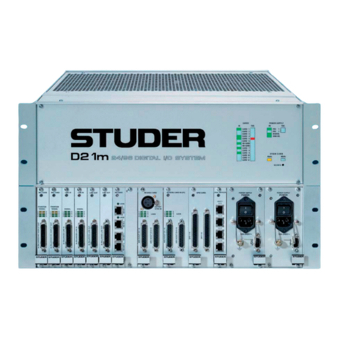
Harman Studer D21m User manual

Harman

Harman Studer D21m User manual

Harman C411 L User manual

Harman

Harman C411 L User manual

Popular Recording Equipment manuals by other brands

Better Music Builder DX-5000 G2 owner's manual

Better Music Builder

Better Music Builder DX-5000 G2 owner's manual

Network Electronics Flashlink DLY-AES user manual

Network Electronics

Network Electronics Flashlink DLY-AES user manual

Danfoss EKC 366 user guide

Danfoss

Danfoss EKC 366 user guide

Keysight 82357B user guide

Keysight

Keysight 82357B user guide

Waves Roland XI-WSG user guide

Waves

Waves Roland XI-WSG user guide

Yamaha TG100 Reference manual

Yamaha

Yamaha TG100 Reference manual

evertz 7740DLY-HD Series manual

evertz

evertz 7740DLY-HD Series manual

FONESTAR M-203 instruction manual

FONESTAR

FONESTAR M-203 instruction manual

Shure PSM1000 Guía del usuario

Shure

Shure PSM1000 Guía del usuario

Studio Technologies 5204 user guide

Studio Technologies

Studio Technologies 5204 user guide

QRS PNO3WB instructions

QRS

QRS PNO3WB instructions

Boston Acoustics SP4 Specifications

Boston Acoustics

Boston Acoustics SP4 Specifications

Connects2 Vision CAM-LR6-AD quick start guide

Connects2

Connects2 Vision CAM-LR6-AD quick start guide

Yamaha DEQ5E Operation manual

Yamaha

Yamaha DEQ5E Operation manual

Elster PFA technical information

Elster

Elster PFA technical information

Helmer i.C3 user guide

Helmer

Helmer i.C3 user guide

BOSSCO Gigcaster 8 Reference manual

BOSSCO

BOSSCO Gigcaster 8 Reference manual

Lexicon OMEGA - ANNEXE 723 owner's manual

Lexicon

Lexicon OMEGA - ANNEXE 723 owner's manual

manuals.online logo
manuals.online logoBrands
  • About & Mission
  • Contact us
  • Privacy Policy
  • Terms and Conditions

Copyright 2025 Manuals.Online. All Rights Reserved.