manuals.online logo
Brands
  1. Home
  2. •
  3. Brands
  4. •
  5. Harman
  6. •
  7. Recording Equipment
  8. •
  9. Harman AMX TPI-PRO-DVI Series User manual

Harman AMX TPI-PRO-DVI Series User manual

QUICK START GUIDE
TPI-PRO-DVI-2/4 Total Presentation Interface with DVI
Overview
The TPI-PRO-DVI Presentation Interface with DVI displays up to 4 fully-scalable video
windows, each supporting Composite, S-Video, Component, VGA and DVI signals on third
party touch monitors (FIG. 1).
There are two versions of the TPI-PRO-DVI available:
•TheTPI-PRO-DVI-2 (FG2275-112) supports up to two DVI inputs.
•TheTPI-PRO-DVI-4 (FG2275-114) supports up to four DVI inputs.
Product Specif ications
The following table lists the specifications for the TPI-PRO-DVI-2 and TPI-PRO-DVI-4. Note
that the primary difference between the TPI-PRO-DVI-2 and TPI-PRO-DVI-4 is in the number of
inputs. In terms of functionality and specifications, they are otherwise identical. The
specifications listed below apply to both versions, unless specifically noted.
Before You Start
The TPI-PRO-DVI has been factory setup with specific touch panel pages. The first splash
screen that appears indicates the TPI is receiving power, loading firmware, and preparing to
display the default touch panel page.
When the panel is ready, the AMX Splash Screen is replaced by the initial Panel Setup page.
• Verify you are using the latest NetLinx Master firmware.
• Verify you are using the latest TPI-PRO-DVI firmware.
• Verify you are using the latest versions of NetLinx Studio and TPDesign4.
FIG. 1 TPI-PRO-2/4-DVI (TPI-PRO-4-DVI SHOWN)
TPI-PRO-DVI SPECIF ICATIONS
•Power
Requirements:
• Constant current draw: 2.6 A @ 12 VDC
• The PSN6.5 Power Supply (FG423-41 - not included) is recommended, to
accommodate all possible configurations and respective power draws.
• Memory: • 256 MB SDRAM
• 256 MB disk memory
• Supported Video
Resolutions:
Input DVI Video:
• up to 1920 x 1200
• single-link DVI only
Input Component Video:
• NTSC 480i, 480p
• PAL 576i, 576p
• 720p, 1080i, 1080p
Input Composite Video and S-Video:
•NTSCM/J
• NTSC 4.43
•PALB/D/I/G/H
•PAL60
• PAL M / N / Nc
•SECAMB/D/G/K/L
• Supported Audio
Sample Rates:
48000Hz, 44100Hz, 32000Hz, 24000Hz, 22050Hz, 16000Hz, 12000Hz,
11025Hz, and 8000Hz.
Front Panel Components
•Power
switch/LED:
Toggles the unit off and on.
• Light Off: Power to the unit is either not plugged in, below approximately
10VDC, above approximately 19VDC, or cross-wired.
• Constant Green: Power to the unit is within nominal voltage limits (between
10VDC and 19VDC, approximately), the unit is on, and all internal power
supplies are operating normally.
• Constant Yellow: Power to the unit is within nominal voltage limits (between
10VDC and 19VDC, approximately) and the unit has been turned off by
pressing the power switch for more than two seconds.
• Flashing Yellow: Power to the unit is within nominal voltage limits (between
10VDC and 19VDC, approximately), but one or more of the internal power
supplies are not operating correctly. The unit needs to be serviced. Contact
AMX Technical Support for further instructions.
•USBType-A
Host ports:
2 USB Type A ports for connecting up to one annotation touch monitor and
up to one keyboard/mouse.
Note: Do not use a USB hub to connect multiple USB devices to the PI.
• Serial port: DB9 connector (male) connects to a DB9 serial port on a PC.
• Status LED: • Constant ON: No communication with the NetLinx Master
• Blinking: In communication with the NetLinx Master
• Input LEDs: Yellow LEDs indicate a valid input signal on each source input
(1-4 on the TPI-PRO-DVI-4, 1-2 on the TPI-PRO-DVI-2).
• Buttons: Four white buttons provide access to the following configuration options:
• RESOLUTION: Opens a screen used to select the TPI-PRO-DVI output video
signal resolution, ranging from 640 x 480@60Hz to 1920 x 1200@60Hz.
Note: This output resolution setting must not be greater than the resolution on
the connected panel.
• TOUCH: Opens the Panel Information page, where you can select from a
series of serial touch panel drivers, and select the driver that corresponds
to the serial touch panel connected to the TPI-PRO-DVI (via the TOUCH
INPUT connector).
• CALIBRATE: Opens the Calibration page, displaying a series of crosshairs.
These crosshairs are used to calibrate the touch device being used.
• SETUP: Opens the TPI-PRO-DVI firmware setup menu.
Power switch/LED
Status LED
2 USB (Type-A)
Input 1-4 LEDs
Serial (Configuration) port
Input ports
Button - RESOLUTION
Button - TOUCH
Button - CALIBRATE
Button - SETUP
RS-232 Touch Input port
Audio (Stereo) Output
Ethernet (RJ-45) port
Power Connector
VIDEO/VGA/DVI Input 4
VIDEO/VGA/DVI Input 3
VIDEO/VGA/DVI Input 2
VIDEO/VGA/DVI Input 1
DVI Output 2
DVI Output 1
USB (Type-B) Sourc
Keyboard/Mouse
Ports 1-4
USB (Type-A) Inputs
TPI-PRO-DVI SPECIF ICATIONS (CONT.)
Rear Panel Components
• DVI-I Inputs: DVI-I input connectors, one per input source (1-4 on the TPI-PRO-DVI-4,
1-2 on the TPI-PRO-DVI-2). Each input connector supports DVI, VGA
graphics, S-video, composite, and component video.
• DVI-I Outputs: 2 DVI-I (VESA/EIA compatible) output connectors. Both outputs support DVI-
D and analog VGA (RGBHV) outputs.
• Maximum output resolution = 1920 x 1200@60 Hz
• Default output resolution = 1280 x 1024@60 Hz
Note: Refer to the TPI-PRO-DVI Instruction Manual for a listing of Supported
Pixel Display and Refresh Rates.
These connectors display video feeds, G4 graphics and external windowed
video/graphics inputs.
The DVI-I Outputs can be connected to either:
• The touch-panel control display
• The public-view non-touch monitor
Note: The TPI-PRO-DVI does not provide Component (YPbPr) or Interlaced
outputs.
• Source TOUCH,
KEYBOARD/
MOUSE
USB ports:
2 or 4 USB Type-B device ports, one per source computer—for source USB
Touch Monitor, mouse/keyboard control (1-4 on the TPI-PRO-DVI-4, 1-2 on
the TPI-PRO-DVI-2).
Note: Do not use a USB hub to connect multiple USB devices to the TPI.
•HostUSBTouch
Monitor
KEYBOARD/
MOUSE
USB ports:
2 USB Type-A ports that can be used for a keyboard, mouse, external storage
unit, or USB-capable touch panel interface.
Note: Do not use a USB hub to connect multiple USB devices to the TPI.
• ETHERNET
10/100 port:
RJ-45 port provides 10/100 Mbps communication with the NetLinx Master
(via ICSP protocol over Ethernet).
• The Ethernet port automatically negotiates the connection speed (10 Mbps
or 100 Mbps), and whether to use half duplex or full duplex mode.
• This communication is reflected via the front ICSP LED.
•TOUCHINPUT
port:
RS-232 (DB9) 9-pin serial port provides connectivity to a pointer device (i.e.
touch screen) that requires a serial connection.
• AUDIO OUT
connector:
3.5mm mini-jack provides stereo output - for use with line-level (0.707 VRMS)
non-amplified stereo output only.
•Power
connector:
2-pin 3.5 mm mini-Phoenix connector.
• Serial Touch
Drivers:
Go to http://www.amx.com//assets/manuals/TPI-
PRO.Supported.Touch.Monitors.zip to download the most recent List of Touch
Monitors and USB Touch Drivers Tested with the TPI-PRO-DVI (including the
most current listing of tested serial touch panel drivers).
Note: The listing of compatible touch monitors is subject to change due to
undocumented changes that 3rd-party touch monitor manufacturers make to
their products over time. Compatibility at a past date does not guarantee
compatibility in the future, and should be verified before deployment.
• USB Drivers: USB Touch drivers are automatically loaded when the USB Touch Monitor is
detected.
•Button
Assignments:
Button assignments can be modified in TPD4 (not on the TPI-PRO-DVIs.)
• Button channel range: 1 - 4000 button push & feedback (per address port)
• Button variable text range: 1 - 4000 (per address port)
• Button states range: 1 - 256 (General Button; 1 = Off State, 2 = On State)
• Level range: 1 - 600 (Default level value 0-255, can be set up to 1-65535)
• Address port range: 1 - 100
• Communication/
Programming:
Master communication and programming is available via an Ethernet
connection. There are several methods of TPI-PRO-DVI communication and
programming available, including DHCP, Static IP, URL, Listen, Auto, NPD
(UPD) and URL (UPD). Refer to the TPI-PRO-DVI Instruction Manual for details.
• Enclosure: Metal with black matte finish
•Operating/
Storage
Environment:
• Operating Temperature: 0° C (32° F) to 40° C (104° F)
• Operating Humidity: 5% to 85% RH Non-Condensing
• Storage Temperature: -10° C (14° F) to 70° C (158° F)
• Storage Humidity: 0% to 85% RH Non-Condensing
• Dimensions
(HWD):
• 1.72" x 17.00" x 10.54"
(4.37 cm x 43.18 cm x 26.77 cm)
• Weight: 8.25 lbs (3.74 kg)
•Certifications: •RoHS
• FCC (Class B)
•CE
• IEC/EN60950
•Included
Accessories:
• 2-pin PWR connector (41-5025)
• Assembly Kit - Four screws and washers (KA0001)
• Rack Ear brackets (60-0900-03)
•OtherAMX
Equipment:
• PSN6.5: Power Supply with 3.5 mm mini-Phoenix connector (FG423-41)
• CC-DVI-5BNCM: DVI-to-5 BNC Male Adapter Cable (FG10-2170-08)
• CC-DVI-RCA3M: DVI-to-3 RCA Male Adapter Cable (FG10-2170-09)
• CC-DVI-SVID: DVI-to-S-Video Adapter Cable (FG10-2170-10)
• CC-DVIM-VGAF: DVI-to-VGA Adapter Cable (FG10-2170-13)
© 2015 Harman. All rights reserved. Netlinx, AMX, AV FOR AN IT WORLD, and HARMAN, and their respective logos are registered trademarks of
HARMAN. Oracle, Java and any other company or brand name referenced may be trademarks/registered trademarks of their respective companies.
AMX does not assume responsibility for errors or omissions. AMX also reserves the right to alter specifications without prior notice at any time.
The AMX Warranty and Return Policy and related documents can be viewed/downloaded at www.amx.com.
3000 RESEARCH DRIVE, RICHARDSON, TX 75082 AMX.com | 800.222.0193 | 469.624.8000 | +1.469.624.7400 | fax 469.624.7153
AMX (UK) LTD, AMX by HARMAN - Unit C, Auster Road, Clifton Moor, York, YO30 4GD United Kingdom • +44 1904-343-100 • www.amx.com/eu/
93-2275-12 REV: H
Last Revised: 10/05/2015
Installation/Safety Instructions
• Connect the unit only to a properly-rated supply circuit.
• DO NOT stand other units directly on top of the TPI-PRO-DVI when it is rack mounted, as
this will place excessive strain on the mounting brackets.
• ALWAYS ensure that the rack enclosure is adequately ventilated.
- Adequate ventilation is critical for proper operation of the TPI-PRO-DVI.
- The TPI-PRO-DVI uses the bottom cover as a heat sink. In most installations it will be necessary
to have some amount of airflow across the bottom cover.
- It is good practice to leave 1 RU of empty space above and below the unit.
- Placing the unit low in the rack, using vented spacer panels and keeping other heat-generating
equipment away from the unit can also be beneficial.
- Depending on the rack enclosure and the surrounding air temperature, it may also be necessary
to incorporate rack fans to increase air flow across the bottom of the unit.
The TPI-PRO-DVI occupies one rack unit in a standard 19" equipment rack. The included
mounting brackets can be rotated 90° in any direction to accommodate several different
mounting options, including tabletop, under/over the table, and vertical wall mounting.
Connections Overview
FIG. 2 illustrates how all of the basic connections on the TPI-PRO-DVI are used in a basic
installation:
Cable Details and Pinouts
Refer to the TPI-PRO-DVI Instruction Manual.
Startup Routine and Initial Panel Response
• Discharge any acquired static electricity by touching a grounded metal object.
• Verify the rear connections are secure and active.
1. Connect the 12VDC Power Supply to the PWR connector on the rear panel. The TPI will
power ON and initialize the startup routine when the power supply is connected.
Note: Once power is applied, use the Power button to toggle the unit off and on.
2. After the startup routine, the connected touch monitor displays one of two possible
screens:
• If the TPI’s output resolution matches that of the touch monitor, continue by setting the
touch drivers associated with the touch monitor.
Note: Refer to the Available Pixel Display and Refresh Rates section in the TPI-PRO-DVI
Instruction Manual for a comprehensive list of Touch Monitors that have been tested with
the TPI-PRO-DVI.
• If the TPI’s output resolution does not match the resolution of the connected touch
monitor, you must set the output resolution of the TPI to match the touch monitor.
Note: An "OUT OF RANGE" message is often generated by the touch monitor. Some monitors will
not display a message, but will appear blank instead.
Setting the Output Resolution
The TPI’s output resolution must match the output pixel resolution and refresh rate set on the
connected touch monitor.
• The default output resolution is 1280 x 1024 @ 60Hz.
• The maximum output resolution is 1920 x 1200 @ 60 Hz.
Note: The TPI-PRO-DVI does not provide Component (YPbPr) or Interlaced outputs.
•UsetheRESOLUTION pushbutton to alter the outgoing resolution to match the output
pixel resolution and refresh rate set on the connected touch monitor.
1. Press the RESOLUTION pushbutton to open the Resolution Setup page.
2. Press RESOLUTION again to cycle through the available output resolution settings.
• Every consecutive button push cycles the output resolution to the next highest setting.
• Double-push the RESOLUTION button to return to the previous setting.
• For a listing of available pixel display and refresh rates, refer to the TPI-PRO-DVI
Instruction Manual.
3. The message "Please wait, loading new resolution..." indicates that the new resolution
setting is being saved. Do not remove power while the new settings are being saved.
4. Once your resolution is selected, you can use the outer screen area lines on the
Resolution Setup page to adjust your monitor’s visible screen area.
• This could involve using the monitor’s video control to stretch and move the incoming
video so that the borders follow the edges of the screen without disappearing.
• There are normally 60 seconds before the resolution times-out, but you can press the
front panel RESOLUTION button again to return to the previous resolution pattern and
continue setting up the monitor.
5. Press and hold the RESOLUTION button to save the resolution setting and exit the
Resolution Setup page.
Note: When the new output resolution is applied, there may be some shifting of the default Main
page, as it was developed for 1280 x 1024.
Setting the Touch Drivers (Serial Touch Monitors Only)
After matching the resolution between the TPI and panel/monitor, the next step is to select the
necessary touch drivers from the driver set provided by the TPI.
• This step only applies to serial touch monitors, as USB monitors are automatically
detected.
• The touch drivers are set when you connect the TPI to a touch monitor.
• The default Touch Input Driver is EloTouch©.
• If you are using a non touch-enabled monitor, select NullTouch.
1. Press the TOUCH pushbutton on the front panel to open the Panel Information page.
2. Press the front panel TOUCH button to cycle through the list of available Touch Input
Drivers.
Note: Go to http://www.amx.com//assets/manuals/TPI-PRO.Supported.Touch.Monitors.zip to
download the most recent List of Touch Monitors and USB Touch Drivers Tested with the
TPI-PRO-DVI (including the most current listing of tested serial touch panel drivers).
Note: The listing of compatible touch monitors is subject to change due to undocumented changes that
3rd-party touch monitor manufacturers make to their products over time. Compatibility at a past date
does not guarantee compatibility in the future, and should be verif ied before deployment.
Verify that the selected Touch Input Driver matches the connected touch monitor.
Calibrating the TPI-PRO-DVI
If the wrong touch driver is selected prior to the calibration process, press any of the front-
panel pushbuttons to exit the calibration process and re-select another touch driver. If you are
using a non touch-enabled monitor, do not press the calibrate button. Refer to the TPI-PRO-DVI
Instruction Manual for screen adjustment procedures.
Calibrating the TPI-PRO-DVI Using a USB Input
1. Connect a USB cable from a touch panel to one of the Type-A USB ports on the front or
back of the TPI.
2. Press the POWER button on the front panel to reboot the TPI and allow the unit to detect
the new hardware.
3. Press the CALIBRATE button on the front panel to open the Calibration page.
4. Press the crosshairs to set the calibration points on the LCD.
5. After the "Calibration Successful." message appears, press anywhere to return to the
Setup page. If the calibration fails, attempt to calibrate again. If unsuccessful, call AMX
Tech Support.
Note: It is recommended that you calibrate the TPI before its initial use, after completing a
firmware download, and after switching Touch Input Drivers (and touch devices.)
6. Press the Protected Setup button (located on the lower-left of the panel page) to open
the Protected Setup page.
7. Enter 1988 in the Password field and press Done when finished.
8. Press the on-screen Reboot button to cycle power to the TPI and incorporate the new
settings. The touch monitor will go blank for a few seconds during the reboot process.
Calibrating the TPI-PRO-DVI Using a Serial Touch Panel
1. Connect a DB9 cable from a touch panel to the DB-9 touch input connector on the back
of the TPI.
2. Press the POWER button on the front panel to reboot the TPI and allow the unit to detect
the new hardware.
3. Press the CALIBRATE button on the front panel. This process opens a calibration page
that uses a series of crosshair coordinate intersections to calibrate the touch panel
(using the newly selected touch driver).
Note: If the wrong touch driver is selected prior to the calibration process, press any front-panel
button to exit the calibration process and re-select another touch driver.
4. Press the crosshairs (on the Calibration page) to set the calibration points on the LCD.
5. After the "Calibration Successful." message appears, press anywhere to return to the
Setup page. If the calibration fails, return to the Protected Setup page and select
another touch input driver.
6. Press the Protected Setup button (located on the lower-left of the panel page) to open
the Protected Setup page.
7. Enter 1988 into the Keypad’s password field and press Done when finished.
8. Press the on-screen Reboot button to cycle power to the TPI and incorporate the new
settings. The touch monitor goes blank for a few seconds during the reboot process. You
can also use a mouse to press the on-screen Reboot button.
9. Upon start-up, press anywhere on the screen to return to the Protected Setup page and
begin defining the communication properties (refer to the TPI-PRO-DVI Instruction
Manual for information).
Additional Documentation
For detailed cabling, installation, configuration, programming, and operating instructions,
refer to the TPI-PRO-DVI Instruction Manual available on-line at www.amx.com.
FIG. 2 TPI-PRO-DVI - BASIC WIRING CONNECTIONS
USB Device Port 4 - to PC #4 (provides pass-through control of PC #4)
USB Device Port 3 - to PC #3 (provides pass-through control of PC #3)
USB Device Port 2 - to PC #2 (provides pass-through control of PC #2)
USB Device Port 1 - to PC #1 (provides pass-through control of PC #1)
USB Touch Input connectors (2)
connect to up to two USB (Type A) touch devices (i.e. Mouse/Keyboard/Touch Screen)
Note: 2 additional USB Touch Input connectors are provided on the front panel, for ease-of-access.
Each of the USB Device ports (1-4) connect to the PC that is providing
video to INPUTs 1-4, in a direct 1-to-1 correlation:
USB Device Port #1 connects to the PC that is providing video to INPUT 1,
USB Device Port #2 connects to the PC that is providing video to INPUT 2, etc.
These Device Ports provide USB Mouse/Keyboard/Touch Screen pass-through
control of the PCs displaying on INPUTS 1-4.
INPUT 4 - Video input from PC #4
INPUT 3 - Video input from PC #3
INPUT 2 - Video input from PC #2
INPUT 1 - Video input from PC #1
TOUCH INPUT DB-9 connector
allows you to connect one Serial-controlled touch device (i.e. RS232 Touch Screen)
OUTPUT 2 - video output to display device #2
OUTPUT 1 - video output to display device #1
Only one touch monitor at a time can be connected.
This manual suits for next models

2

Other Harman Recording Equipment manuals

Harman Lexicon MX400 User manual

Harman

Harman Lexicon MX400 User manual

Harman Lexicon MC-10 How to use

Harman

Harman Lexicon MC-10 How to use

Harman DBX 162SL User manual

Harman

Harman DBX 162SL User manual

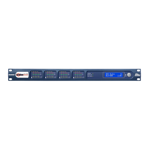
Harman Soundweb London BSS BLU-800 User manual

Harman

Harman Soundweb London BSS BLU-800 User manual

Harman BLU-Si Service manual

Harman

Harman BLU-Si Service manual

Harman AMX N2600S Series User manual

Harman

Harman AMX N2600S Series User manual

Harman AMX AXB-DMX512 User manual

Harman

Harman AMX AXB-DMX512 User manual

Harman AMX AXB-232++ User manual

Harman

Harman AMX AXB-232++ User manual

Harman JBL VTX Series User manual

Harman

Harman JBL VTX Series User manual

Harman Lexicon PCM96 Surround User manual

Harman

Harman Lexicon PCM96 Surround User manual

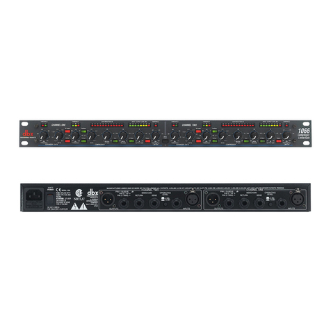
Harman DBX 1066 User manual

Harman

Harman DBX 1066 User manual

Harman BSS Audio Soundweb London LU-800 User manual

Harman

Harman BSS Audio Soundweb London LU-800 User manual

Harman BSS Soundweb London BLU-USB User manual

Harman

Harman BSS Soundweb London BLU-USB User manual

Harman Crown DSi 8Mn User manual

Harman

Harman Crown DSi 8Mn User manual

Harman C411 L User manual

Harman

Harman C411 L User manual

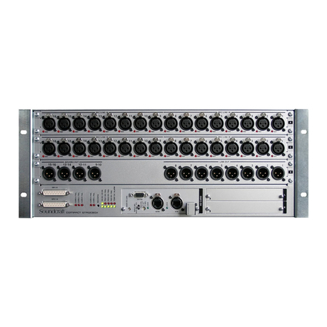
Harman Soundcraft Compact Stagebox Troubleshooting guide

Harman

Harman Soundcraft Compact Stagebox Troubleshooting guide

Harman dbx go Rack User manual

Harman

Harman dbx go Rack User manual

Harman Lexicon MC-10 Quick start guide

Harman

Harman Lexicon MC-10 Quick start guide

Harman AKG DMM8 U User manual

Harman

Harman AKG DMM8 U User manual

Harman dbx DJdi User manual

Harman

Harman dbx DJdi User manual

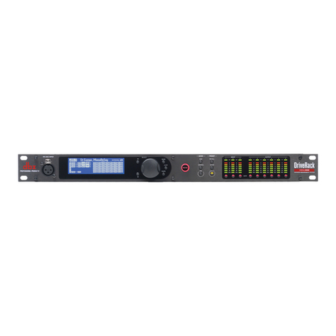
Harman DriveRack VENU360 User manual

Harman

Harman DriveRack VENU360 User manual

Harman AKG C411 Series User manual

Harman

Harman AKG C411 Series User manual

Harman dbx 160SL User manual

Harman

Harman dbx 160SL User manual

Harman BSS Soundweb London BLU-HIF User manual

Harman

Harman BSS Soundweb London BLU-HIF User manual

Popular Recording Equipment manuals by other brands

Thonk Eurorack instructions

Thonk

Thonk Eurorack instructions

Toa SS-9001 Specifications

Toa

Toa SS-9001 Specifications

Woodhead SST-DN3-104-1 Hardware reference guide

Woodhead

Woodhead SST-DN3-104-1 Hardware reference guide

Akai MPC Reference manual

Akai

Akai MPC Reference manual

Siemens SINAMICS S120 Installation and start-up manual

Siemens

Siemens SINAMICS S120 Installation and start-up manual

Fostex 4050 owner's manual

Fostex

Fostex 4050 owner's manual

ifak system H@rt BluePack user manual

ifak system

ifak system H@rt BluePack user manual

Solinst AquaVent SDI-12 user guide

Solinst

Solinst AquaVent SDI-12 user guide

Cochlear Nucleus 7 Guide

Cochlear

Cochlear Nucleus 7 Guide

Bticino SCART Nstructions for use

Bticino

Bticino SCART Nstructions for use

dbx 231s Brochure & specs

dbx

dbx 231s Brochure & specs

Miditech Pianobox USB owner's manual

Miditech

Miditech Pianobox USB owner's manual

M-Audio 24Bit/96kHz Recording System Delta 66 Bedienungsanleitung

M-Audio

M-Audio 24Bit/96kHz Recording System Delta 66 Bedienungsanleitung

Velleman K8045 manual

Velleman

Velleman K8045 manual

Panasonic AYNE2000 - NONLINEAR AV WORKSTA installation manual

Panasonic

Panasonic AYNE2000 - NONLINEAR AV WORKSTA installation manual

AUDIO IMPERIA FVDE user manual

AUDIO IMPERIA

AUDIO IMPERIA FVDE user manual

Zoom PFX-9003 Operation manual

Zoom

Zoom PFX-9003 Operation manual

A&D HP-05 instruction manual

A&D

A&D HP-05 instruction manual

manuals.online logo
manuals.online logoBrands
  • About & Mission
  • Contact us
  • Privacy Policy
  • Terms and Conditions

Copyright 2025 Manuals.Online. All Rights Reserved.