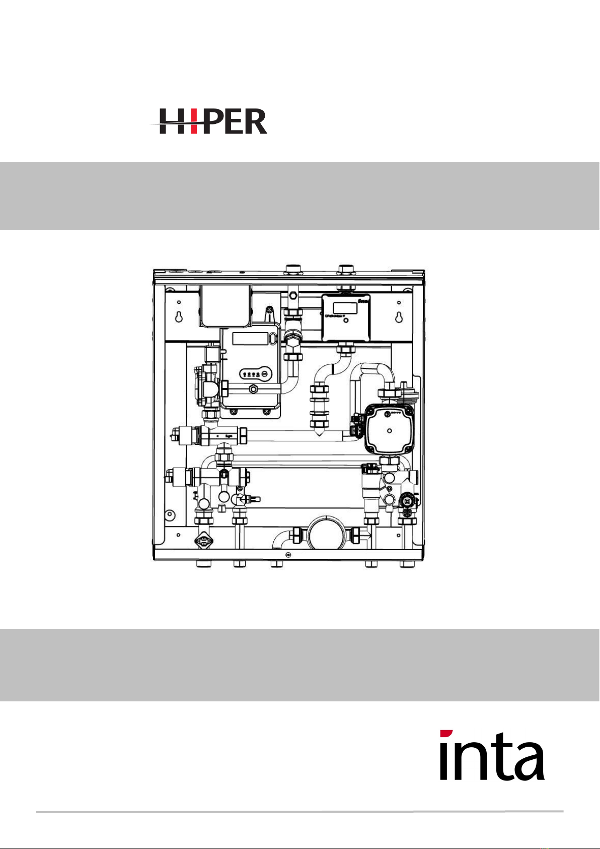
Inta HIPER-V3 DIRECT User manual
In this document Inta have endeavoured to make all the informaon
and procedures accurate. Inta cannot accept responsibility should it
be found that in any respect the informaon is inaccurate or
incomplete as a result of future developments.
05/20 E&OE
Installaon Instrucons
V3 Single Plate Heat Interface Units
Instantaneous hot water and direct Heang .
-V3 DIRECT

These instrucons describe the installaon, assembly, operaon, maintenance and fault nding of the Hiper Heat
Interface Unit (HIU). For operaon of the enre plant, the technical documentaon of all the components used
such as, boiler, tank, pumps, pipework and valves must be complied with. Inta does not accept any responsibility
for the design and performance of the heat network or components outside of the HIU.
Installaon should only be carried out by a qualied and competent plumbing installer and a qualied and
competent electrical installer in accordance with the current Building, Water and Electrical Regulaons, Legislaon
and Standards. Do not start installaon unl you have thoroughly read and understood these Assembly and Oper-
ang Instrucons and have complied with all safety provisions.
Symbols used in this manual :
DANGER – immediate risk of physical injury or even death.
DANGER – immediate risk of serious damage.
IMPORTANT – informaon crical to the installaon or installer.
IMPORTANT – informaon crical to the user.
NOTE – useful informaon regarding the operaon or installaon of the HIU.
SECTION 1 - Important informaon and introducon
Heat Interface Units (HIU) deliver heat generated from a centralised heang plant to mulple homes,
apartments or ats. The Inta Hiper V3 HIU interfaces the heat network and dwellings systems
through a plate heat exchanger to provide hot water (DHWS) and with room heang (HTG) in a DIRECT
connecon to the heat network.
HIUs do not generate their own heat so to deliver DHW and CH most suitable for the requirement of the
home or apartment it is the responsibility of the installer and or system designer that the heat network
delivers heat at
sucient ow rate and temperature to do so.
05/20 E&OE
Installaon and Operang Instrucons SECTIONS
Page 2
1. Important Informaon and Introducon
2. Descripon
3. Dimensions
4. Technical Data
5. Installaon
6. Operaon of Unit
7. Commissioning
8. Fault Finding
9. Servicing
10. Warranty
-V3 DIRECT

Hot Water Priority
Preheat Funcon to keep hot water heat exchanger warm
Heang ramp up within 3 minutes
Unit shutdown if heang temperature goes to 50-55°C on Underoor Model
Pump an-lock feature – runs pump 5 secs every 24 hours
An Calcicaon pump run on aer hot water provision
Features
• Cools the plate aer hot water producon for prolonged life for the plate heat exchanger.
• Addional shunt pump inside the staon, so pump power from the plant room can be signicantly reduced as
the plant room pump will not have to deal with the pressure losses within the ats
• Heang ow temperature can be controlled from 30°C to 80°C.
• Direct supply for Under Floor Heang OPTION UFH protecon with a safety switch.
• Plus an addional UFH protecon with a safety switch.
• Safety during a power cut. Inlet valve is fail safe, and will not allow overheang of the DHW plate or to any
UFH low temperature circuits when the electronic control is not funconing.
• Mixing valve basically controls ow temperature of water to the heang or hot water.
• Pump bypass that works automacally if the unit is in heang mode and all circuits are closed. Water ow
passes through the bypass around the heat exchanger protecng the pump.
• Electronic Controller, with manual temperature adjustment.
• Shut o valve for either UFH high temperature protecon, or Pre-Payment shut down when out of credit.
No addional shut down valve required.
Model - HIUV3-40 DIRECT type HIU with Priority Hot Water
(Oponal Model - HIUV3-40 DIRECT type HIU with Priority Hot Water for UFH)
Accessories and Opons;
• with Cold Water Supply connecon
• With ed Heat Meter
• With cold water meter (only for sub-metering, not billing)
• Isolaon Ball Valve Kit HIAC03BVPACK
• First Fix JIG
Secon 2 - Descripon
Page 3
05/20 E&OE
-V3 DIRECT

Secon 3 - Dimensions
05/20 E&OE
Page 4
10mm 10mm
300mm
300mm
clearances
300mm
-V3 DIRECT

Secon 4 - Technical Data
Page 5
05/20 E&OE
HIUV3-40 Data
Maximum operang pressure bar 10
Maximum Hot Water Flow Rate l/min 14 to 18
Maximum District Flow Rate l/min 18
Maximum Pressure dierenal bar 3
Weight (empty/ installed) kg 21
Available Sengs
Temperature of Heang – Low Mode ºC 30 – 45
Temperature of Heang – High Mode °C 30 – 80
Temperature of Hot Water ºC 40 – 60
Hot Water Performance 40 Plate
10°C to 50°C at 14 l/m Kw
Primary Flow 0.266 ltrs /sec
50kW
Max DHWS Flow Ltrs/min 18
Min DHWS Pressure bar 1.5
Max Hot water temperature 10 bar
Heang Performance
At 18l/m and ΔT of 15°C kW 15
‘District’ Heat Provision
Maximum Inlet Temperature ºC 85
Minimum required ‘District ‘ow
rate @ 80°C to provide Hot Water
10 to 50°C at max ow rate l/min
9.36
Minimum required ‘District’ ow
rate @ 70°C to provide Hot Water
10 to 50°C at max ow rate l/min
11.98
Maximum Pressure 10 bar
Electrical Data
Electrical Supply 230V AC 50Hz 1Ph
Power consumpon full load was 105
Connecon Data
‘District’ Inlet and Outlet 3/4” Male BSP
Heang System Inlet and Outlet 3/4" Male BSP
Cold Water Inlet / Hot Water Outlet 1/2" Male BSP
-V3 DIRECT

Page 6
Secon 5 - Installaon
05/20 E&OE
Note – when working with the unit, supply services when connected could reach 85°C, and once elec-
trically connected the staon has 230V present within.
5.1 Locaon
The unit is designed for wall mounng. The unit can be mounted using either a wall bracket or spacer
hanging bracket [see Fig 5]. The spacer hanging bracket provides space to run pipes behind the unit if
required.
MOUNTING BRACKET
SPACER HANGING BRACKET
5.2 Pipework Connecons
The ‘district’ and apartment pipework should be connected to the appropriate points labelled on the drawing in
Secon 3 Dimensions. It is advisable to provide means of isolaon and disconnecon [via unions] on all
connecons to the unit to facilitate replacement of the unit if this is ever required. Inta only recommend using
Inta dedicated connecons kits as tabled below. You need to ensure that the systems you are connecng to, are
clean or have been ushed out appropriately.
ACCESSORIES for HIUV3-40 SINGLE PLATE HIU range
60mm Stand-off Brackets ALV3ACBKT60
PACK OF 4 SECONDARY BALL VALVES PACK, WRAS APPROVED HIAC03BVPACK
HIUV3 qty 1/2" MF Ballvalve Pack ALV3BV
-V3 DIRECT

Page 7
05/20 E&OE
Secon 5 - Installaon
5.2 Pipework Connecons
District’ Inlet and Outlet – 3/4" Male BSP
These are situated at the top of the staon, with inlet on the le [Connecon 1 – Secon 3 and outlet on the right
[Connecon 2 – Figure 6]. When connecng the district supply to and from the unit, ensure to provide automac
air vent at upper most point of pipework.
Heang Inlet and Outlet – 3/4" Male BSP
These are situated at the boom of the staon with the heang ow on the far le [Connecon 3 - Secon 3] and
heang return on the far right [Connecon 7 – Secon 3]. Connect these to your heang distribuon system.
Cold Water Inlet/Outlet and Hot Water Outlet – 1/2" Male BSP
These are situated at the boom of the staon with the cold water inlet the middle of the ½” connecons
[Connecon 5 – Secon 3]. There is a cold water outlet if staon is provided with cold water meter to the le of
the heang return [Connecon 6 - Secon 3]. The hot water outlet is to the right of the heang ow [Connecon 4
- Secon 3. Connect your mains cold water to the cold water inlet and outlet if being used in accordance with local
by-laws, and connect your hot water distribuon pipe to the hot water outlet on the staon.
5.3 Electrical connecons
All wiring to the unit must be in accordance with the IEE
regulaons, and any local regulaons which apply.
Note: If in any doubt a qualied electrician should be consulted.
The unit is supplied with a 2m 3-core ying lead for connecon to
mains supply. Mains connecon must be done through a fused
isolator rated at 3 Amps and posioned locally to the unit.
Also provided is a 2m 2-core ying lead for connecon to a room
thermostat.
No Descripon Individual Wiring Connector
28 Remote Controller/
Temperature Sensor
2 Black n/a
30 DHW Temperature Sensor 2 White Black Connector
31 DHW Flow Sensor Red, White and Blue White Connector
32 Mixing Valve Stepper Motor Blue, Black, Brown and Green White Connector
33 Mains Cable Blue, Brown and Green/
Yellow
n/a
34 Earth Cable Green/Yellow Uninsulated Crimp
Ring
35 Pump N/a Black Connector
36 Diverter Valve Stepper Motor Blue, Black, Brown and Green Blue Connector
37 CH Temperature Sensor 2 Red Black Connector
38 Solenoid Valve 2 White 2 Terminal Crimps
39 CH Safety Thermostat 2 Black 2 Terminal Crimps
-V3 DIRECT
Operaon of the unit
05/20 E&OE
Page 8
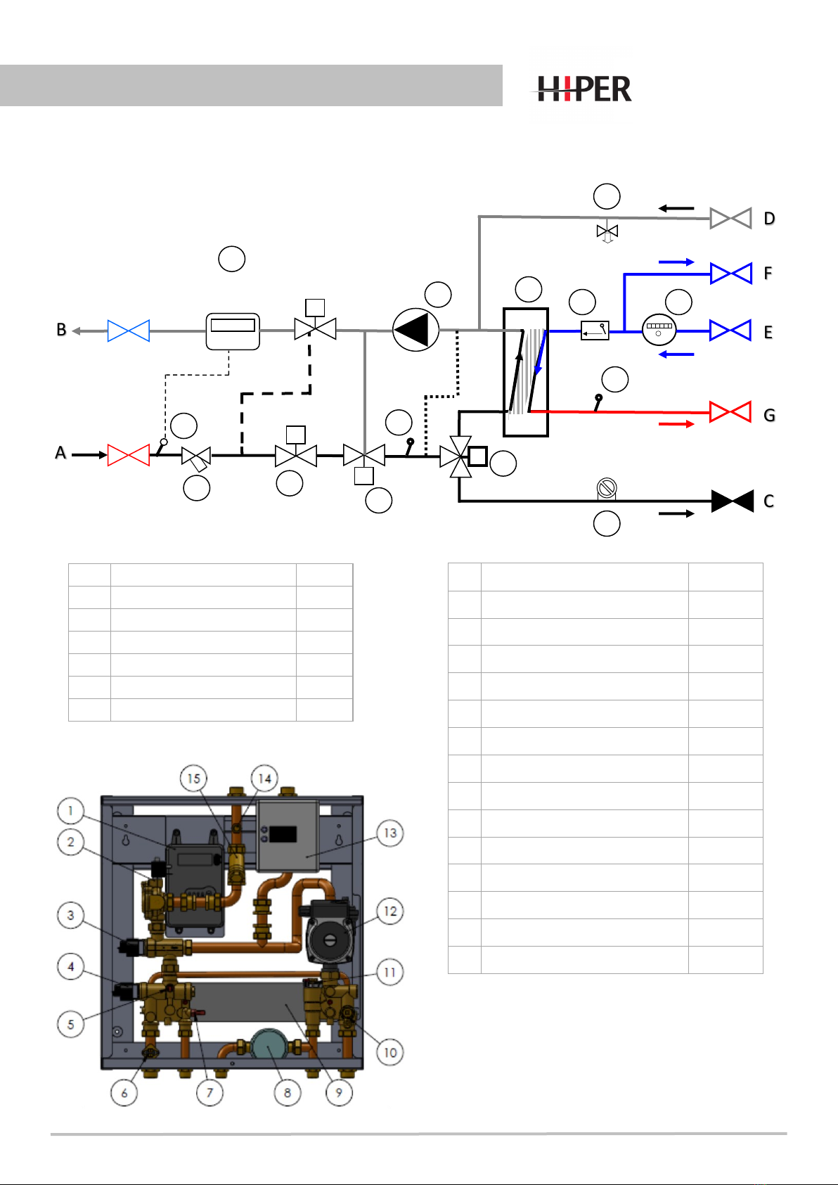
6.0 Schemac and main components
DH
Primary Flow
DH
Primary Return
Mixing Valve
F
A
E
D
C
B
G
2
5
6
3
4
8
10
7
11
15
14
13
12
DPCV
(oponal extra)
Heat Meter
(oponal extra) 9
APrimary FLOW connecon 3/4” M
BPrimary RETURN connecon 3/4” M
CCentral Heang FLOW 3/4” M
DCentral Heang RETURN 3/4” M
ECOLD water IN supply connecon 1/2” M
FCOLD water OUT supply OPTION 1/2” M
GHOT Water OUT (DHWS) 1/2”M
1Electronic Controller TH860001
2Solenoid Zone Valve TH920003
3Mixing Valve Stepper Motor TH960001
4Diverter Valve Stepper Motor TH960001
5CH Temperature Sensor TH980001
6CH Safety Cut Out Klixon EL800026
7DHW Temperature Sensor TH980001
8Water Meter TBA*
9Heat Exchanger 40 Plate HE884098
10 Drain Valve PF920007
11 DHW Flow Switch TH860003
12 Pump Erp compliant TH900003
13 Heat Meter Calculator TBA*
14 Heat Meter Temp. Sensor TBA*
15 Strainer PF941020
-V3 DIRECT
Secon 6 - Operaon of the unit
Page 9
05/20 E&OE
6.1 Unit Operaon
Whenever power is applied to the staon, the stepper motors are reset to ensure they are in their correct posion,
so you are likely to hear a clicking noise from the motors. This is normal. Once the motors are in their correct posi-
on the unit is ready for its operaon.
6.2 Heang
When there is a heang requirement, as programmed in your controller or room thermostat, the staon will go into
heang mode. The diverter valve will switch to heang port, the solenoid valve will open, the pump will come on,
and the mixing valve will start to operate and will gradually ramp up the temperature of the heang water to the
set temperature over a period of up to 3 minutes. The unit will connue to provide heang [at set temperature or
‘district’ inlet temperature whichever is the lower], unl desired room temperature has been achieved or unit
switches into hot water mode, where the solenoid valve will close, and the pump will stop. The unit will restart its
heang cycle every me it switches in to heang mode.
The staon will come set as requested if requested at point of order.
Underoor heang mode, which comes with a cut out Klixon that will stop the heang from working if the
heang ow temperature reaches between 50°C and 55°C. If this occurs, then the heang will have to be
reset on the electronic box before heang mode will operate again [see secon 8.0 – Figure 7].
Radiator heang mode.
6.3 Hot Water
Hot Water has priority [unless remote programmer has been programmed otherwise] and when the hot water ow
detector senses a ow of greater than 2.5l/m then the unit switches into hot water mode. The diverter valve will
switch to hot water port, the solenoid valve will open, the pump will come on, and the mixing valve will start to op-
erate, controlling the ‘district’ temperature to the heat exchanger to keep hot water temperature at set tempera-
ture as long as there is sucient temperature in the district ow.
When the ow rate goes below 2l/m then the unit will switch out of hot water mode. The solenoid valve will close
but the pump will connue for 5 seconds to cool down the heat exchanger to reduce lime scaling.
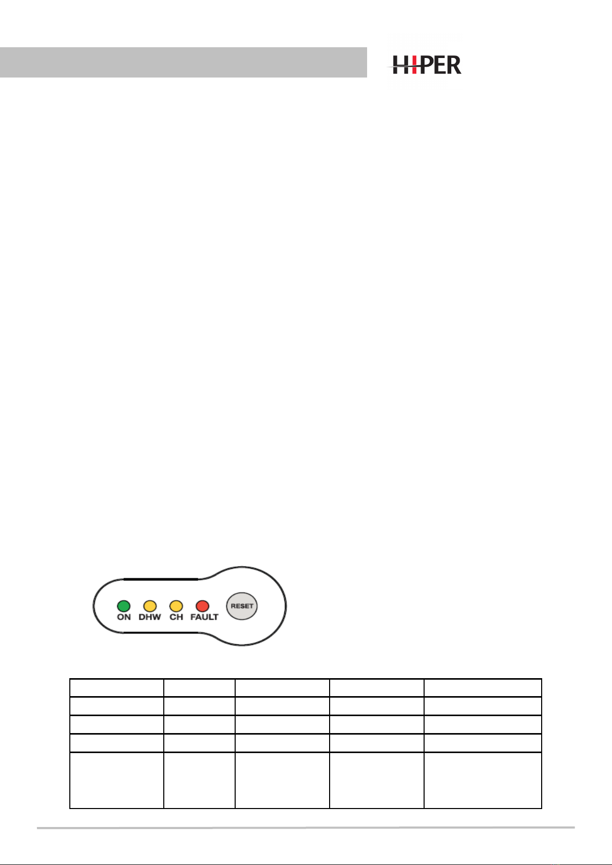
COLOUR LIGHT OFF LIGHT ON LIGHT FLASHING
ON Green Power O Power On N / A
DHW Yellow No DHW Demand In DHW Mode Preheat Running
CH Yellow No CH Demand In CH Mode N / A
FAULT Red No Fault Low Temperature
lockout – re-
quires
reset
Sensor faults – self
restoring when fault
reced
6.4 Controller LED display
-V3 DIRECT

05/20 E&OE
Secon 7 - Commissioning
No.HIU Commissioning Checklist Comment and conrm checked Date
1Record installaon date, product code,
serial number and room number
Installaon Date:
Installer:
Product Code:
Serial No.:
Room No.:
2Verify and record primary: ow,
temperature and pressure.
Flow:
Temperature ⁰C:
Pressure (dynamic) Bar:
3Verify and record if the room
thermostat is voltage free
If the room thermostat is not voltage
free do not turn on power to the HIU
and abort commissioning!
4Verify and record if the primary side
strainer inside the HIU is clean.
5Verify and record in-coming water
main pressure and ow rate is within
the parameters of the HIU specicaon
6Verify and record that any valves in the
Central heang circuit are in the
correct posion. These should be as
the installaon schemac in the M&E
design
7Verify and record that all valves from
the Cold water mains supply to the HIU
are in the correct posion
8Verify and record if present, any
manual bypass valve or pipe is CLOSED
or removed and ushing ports sealed.
9Verify and record if all pipes have
insulaon and if the insulaon is
according to the requirement of
current building regulaons
10 Verify and record if all pipes directly
connected to the HIU are secured and
fastened with adequate pipe clips.
-V3 DIRECT

05/20 E&OE
No.HIU Commissioning Checklist Comment and conrm checked Date
11 Verify and record the Power supply
available.
Check for Earth connuity.
12 Verify and record if the casing is secure
and if all electrical connecons are safe
and conform to current wiring
Regulaons.
13 Switch ON power supply to the unit
and record if any error codes
Address error codes accordingly and
record acons
14 Ensure the room thermostat seng is
above ambient temperature. Verify
and record the HIU has entered
heang mode.
Return room thermostat back to
original temperature
15 For Underoor Heang installaons
verify and record the central heang
ow temperatures to the pipes into
the oor circuits are as specied by the
system designer. Adjust accordingly if
required and verify and record
Return room thermostat back to
original temperature
16 Open a hot water outlet in the
property, verify and record the
temperature of the hot water from the
outlet
17 Validate and register online warranty
Commissioning Company Name
……………………………………………………………………...
Commissioning Engineer Name
………………………………………………………………………….
Date
Date
Secon 7 - Commissioning -V3 DIRECT

Secon 8 - Fault nding
Page 12
05/20 E&OE
FAULT FINDING
If there are no error messages or fault lights, then rstly switch o power to the unit, wait for 10 seconds and then
re-start the unit as this will re-set the stepper motors.
If the unit sll does not operate, then the next step is to check all wiring is correctly connected to the right
component, especially if connectors have been taken o at any stage. Refer to Appendix 2 for wiring explanaon.
Fault Possible Causes Acon
‘District’ water not
entering the unit.
Blocked strainer
Solenoid valve not
operang correctly.
Unscrew the strainer cap bolt and take the strainer out, ensur-
ing you have isolated unit and waited for water to cool down.
Clean or replace accordingly.
Ensure there is posive pressure between inlet and outlet of
valve. Check that 24V is being supplied to the DC coil.
If above does not resolve issue, replace solenoid coil.
No Hot Water or
Heang
Electronics in Fault Mode
Solenoid valve not
operang
Control Valve not
operang or Diverter
Valve no operang
Pump not operang
Hot Water Flow sensor
not working
Safety klixon switch
tripped [if ed]
‘District’ water tempera-
ture too low
Low pressure, re-ll and it will re-set
See above
Check that 24v is being supplied to either or both DC Coils. If
both OK, then replace the faulty stepper motor
Check that impeller has not seized.
Check you have 240 volts going to pump.
If above does not resolve issue, replace pump
Flow rate is below 2.6l/m
If light on with no ow replace the sensor electronic.
If light doesn’t come on with a ow rate of more than 2.5l/m
replace sensor electronic
Review why klixon has tripped out and re-set electronics
If above does not resolve issue, replace klaxon.
Check ‘District’ supply condions
Low Hot Water
ow rate
Heat Exchanger blocked
Blocked cold water
strainer
Flush Heat Exchanger or replace
Take out ow sensor cartridge and check and clean strainer
-V3 DIRECT

Secon 9 - Servicing
Page 13
9.0 SERVICING SCHEDULE
Note – when working with the unit, supply services when connected could reach 85°C, and
once electrically connected the unit has 230V present within.
It is recommended that the unit is serviced once every 12 months to maintain its eciency
and longevity.
9.1 Servicing the Strainer (Part 15 – Figure 9)
Isolate the unit from district supply. Open the screw cap from the strainer and take
the lter cartridge out. Depending on the condion either clean it or replace it and
put the screw cap back on again. Note the district water in the strainer could be
85°C.
-V3 DIRECT

Page 12
Secon 10 - Warranty
05/20 E&OE
Extended Product Warranty
Intatec Limited (company number 04359938) (we, us, our) oers any business customer which
has purchased directly from us (Buyer/you) any of those products which are part of our Hiper
HIU range of products described in paragraph 2 of Secon A of this extended warranty docu-
ment (Hiper HIU), the benet of an extended warranty in respect of manufacturing defects,
subject to the following condions and exclusions.
Secon A: Our Warranty
1. Intatec warrants to the Buyer that the Hiper HIU shall be free from manufacturing defects
under normal and proper use (Warranty) for a period of 3 years following the Warranty
Commencement Date (as dened in paragraph 5 of this Secon A) (Warranty Period).
2. The Warranty only applies to the following products which are part of our Hiper HIU range:
- Twin Plate HIU;
- Single Plate HIU;
- Cooling Interface Unit;
- HIU with HW Cylinder arrangement but not including the cylinder.
3. Subject always to the warranty exclusions set out in Secon B of this extended warranty
document, during the Warranty Period we will repair or replace at our discreon, the Hiper HIU
or any defecve part thereof, which is proven to be a component failure caused by
manufacturing defects.
4. The Hiper HIU must be correctly installed and commissioned by a competent and qualied
installer and in accordance with the installaon manual to which this extended warranty
document is enclosed (which includes the requirement for you to issue to us (or procure the
issue of), those commissioning documents requested by us from me to me such as the
‘Benchmark’ commissioning checklist), otherwise the Warranty may not apply. Proof of installa-
on and commissioning in accordance with this paragraph 4 may be required to validate the
Warranty.
5. The Warranty must be registered by you (or on your behalf) via the internet at hps://
www.intatec.co.uk/register_hiu_product or by post to Intatec Limited, Aireld Industrial Estate,
Hixon ST18 0PF, no later than 30 days following the Hiper HIU being installed at the relevant
property, with the date of installaon being the ‘Warranty Commencement Date’ for the
purposes of the Warranty. In the event that you fail to register the Warranty in accordance with
this paragraph 5, then the Warranty Commencement Date shall be deemed to be the date that
we dispatch the Hiper HIU to you.
6. The Warranty only relates to the Hiper HIU and integrated controls and does not extend to
any connected system or accessories including without limitaon any external pumps, external
wiring, lters and valves.
7. The Warranty only extends to the Buyer and the Buyer shall not assign or transfer its rights or
obligaons under the Warranty without our prior wrien consent. However, nothing in this
paragraph shall prevent the Buyer’s customers and/or the end-users of the Hiper HIU from
contacng us in accordance with paragraph 1 of Secon C.
8. The Warranty is not insurance backed.
Secon B: Warranty Exclusions and Our Liability
1. The Warranty shall not apply and we shall not be liable where:
a) any alteraons or adjustments have been made to the Hiper HIU (including without limitaon
alteraons or amendments to its design and/or construcon);
b) further use is made of the Hiper HIU aer we have been noed of an alleged defect:
c) repairs have been aempted by anyone other than us or our authorised representaves; the
Hiper HIU has been moved from its original place of installaon;
d) defects are caused by:
i. wilful damage, neglect, negligence or abnormal storage or working condions;
ii. accidental or malicious damage (e.g. vandalism) or events outside of our control (e.g. re, ood
or explosion);
iii. the or aempted the;
iv. fair wear and tear;
v. a failure to adhere to installaon, usage, maintenance and/or servicing instrucons provided
(orally or in wring) by us from me to me, including, without limitaon, the installaon
manual issued to you and available via our website at www.intatec.co.uk;
vi. incorrect or improper installaon, ng or use of the Hiper HIU (including without limitaon
where damage is caused to the controller of the Hiper HIU by connecng voltage to
connecons that are in the installaon manual advised as being “Volt Free”);
vii. use of non-genuine spare parts (which have not been approved by us in advance in wring) in
the installaon, maintenance, service or repair of the Hiper HIU;
viii. any problems or defects caused by the supply of services (such as electricity, gas or water) to
the property where the Hiper HIU is installed;
ix. any fault or failure in the systems to which the Hiper HIU is connected (e.g. pumps and boilers);
x. any damage caused by the condion of water which supplies the systems (including without
limitaon hard water scale deposits or sludge resulng from corrosion).
2. The Warranty only applies to any Hiper HIU bought in and installed and used in the United
Kingdom and Republic of Ireland.
3. Except as provided in this extended warranty document and our Standard Terms and
Condions of Sale (which can be found online at www.intatec.co.uk), which form the basis of
the contract between you and us, we shall have no liability to you in respect of any defect in the
Hiper HIU supplied.
4. The terms implied by secons 13 to 15 of the Sale of Goods Act 1979 are, to the fullest extent
permied by law, hereby excluded.
5. We shall in no circumstances be liable to you in contract, tort (including negligence), breach
of statutory duty, or otherwise for any of the following losses arising under or in connecon
with the Warranty:
a) any indirect, consequenal or special losses;
b) any loss of prot (whether direct, indirect or consequenal); and
c) any loss of sales or business (whether direct, indirect or consequenal).
6. Nothing in the Warranty excludes or limits any liability which cannot legally be limited
including liability for death or personal injury caused by negligence or fraud or fraudulent
misrepresentaon.
7. The Warranty shall apply to any repaired or replaced Hiper HIU supplied to you by us. For the
avoidance of doubt, any repair or replacement carried out under the terms of the Warranty
does not extend the Warranty beyond the Warranty Period.
Secon C: How to Claim
1. In the unlikely event that you encounter a problem with the Hiper HIU, you or your customer
and/or end-user should contact us promptly in wring (whether by post or email) or by
telephone, using the contact details set out below in this Secon and in any event within 10
days of the defect becoming evident. Any claim made under the terms of the Warranty must be
made within the Warranty Period.
2. Once you or your customer and/or end-user have contacted us in accordance with paragraph
1 above to report a problem, we will contact you or your customer or end-user (as the case may
be) by telephone in the rst instance so that we can ask a series of inial quesons to get a
beer understanding of the nature of the problem and provide some inial guidance. If we are
unable to resolve the problem by telephone remotely, we will arrange, at a mutually agreed
me, for an engineer to visit the site where the Hiper HIU is installed to examine the Hiper HIU.
3. Please note, health and safety is of paramount importance to us and if our engineers cannot
gain safe access to the Hiper HIU or our engineer cannot gain access to the property where the
Hiper HIU is located, then an aborve charge equal to our ‘inial call out charge’ (as referred to
in paragraph 5 of this Secon C) shall apply and shall be payable by you on demand.
4. Aer examinaon by our engineer, we will arrange to repair or replace any part(s) of the
Hiper HIU, which are in our opinion a component failure caused by manufacturing defects, free
of charge.
Important note: We will require you to provide details of the serial number of the Hiper HIU in
order for us to be able to consider any claim, so please have such details readily available
upon request.
Our contact details:
Email: [email protected]
Telephone: 01889 272180
By Post:
F.A.O Technical Department
Aireld Industrial Estate
Hixon
Staord
Staordshire
ST18 0PF
5. If, aer examinaon by us, we are of the opinion that the defect(s) is/are not covered by the
terms of the Warranty, addional call out charges (including without limitaon an inial call out
charge) shall apply. Details of such charges (and our payment terms) are displayed on our
website at www.intatec.co.uk.
Secon D: General
1. In the event that we receive any personal informaon from you, we will only use such per-
sonal informaon to administer the Warranty. We may share such personal informaon with
our engineers in order to conduct any repairs or replacements covered by the Warranty.
We will process such personal informaon in accordance with our privacy policy (a copy of
which is available on request or can otherwise be found at hps://www.intatec.co.uk/
privacy_policy).
2. This extended warranty document does not give rise to any rights under the Contracts
(Rights of Third Pares) Act 1999 to enforce any term of the Warranty.
3. If the terms and condions set out in this extended warranty document have not been
complied with in full, then we reserve the right to declare the Warranty as null and void.
4. Any words following the terms including, include, in parcular, for example or any similar
expression shall be construed as illustrave and shall not limit the sense of the words,
descripon, denion, phrase or term preceding those terms.
5. If any exclusion or limitaon expressly set out in this extended warranty document is or
becomes invalid, illegal or unenforceable, it shall be deemed deleted, but that shall not aect
the validity and enforceability of the rest of this extended warranty document.
6. The terms of this extended warranty document are subject to the law of England and Wales
and the courts of England and Wales shall have exclusive jurisdicon to sele any dispute or
claim arising out of or in connecon with this extended warranty document.
-V3 DIRECT

05/20 E&OE
-V3 DIRECT
Table of contents


