Force Dimension omega Series User manual

USER MANUAL
omega.x haptic device
version 1.7
06.2013
Force Dimension
Route de Saint-Cergue 295
CH – 1260 Nyon
Switzerland
www.forcedimension.com

2

3
summary
The purpose of this document is
>to describe the setup of the omega.x haptic device
>to describe the installation of the drivers and haptic software SDK
>to describe the operation of the omega.x haptic device
glossary
FD-SDK refers to the Software Development Kit (SDK) for all Force Dimension products.
omega.x refers to the base haptic device shared by the omega.3, omega.6 and omega.7
haptic devices. Unless specified, all instructions in this manual apply to all three
device types.

4

5
table of contents
1.device description 7
2.important safety instructions 8
3.setting up the omega.x 9
3.1unpacking the device 9
3.2installing the power supply 10
4.configuring the omega.x under Windows 11
4.1installing the software 11
4.2installation description 11
4.3installing the drivers 11
5.configuring the omega.x under Linux 12
5.1installing the software 12
5.2installation description 12
5.3installing the drivers 12
6.configuring the omega.x under Mac OS X 13
6.1installing the software 13
6.2installation description 13
6.3installing the drivers 13
7.using the omega.x 14
7.1device geometry 14
7.2operating the omega.x 16
7.3running the HapticDesk program 19
7.4running the demonstrations programs 20
8.technical information 23

6

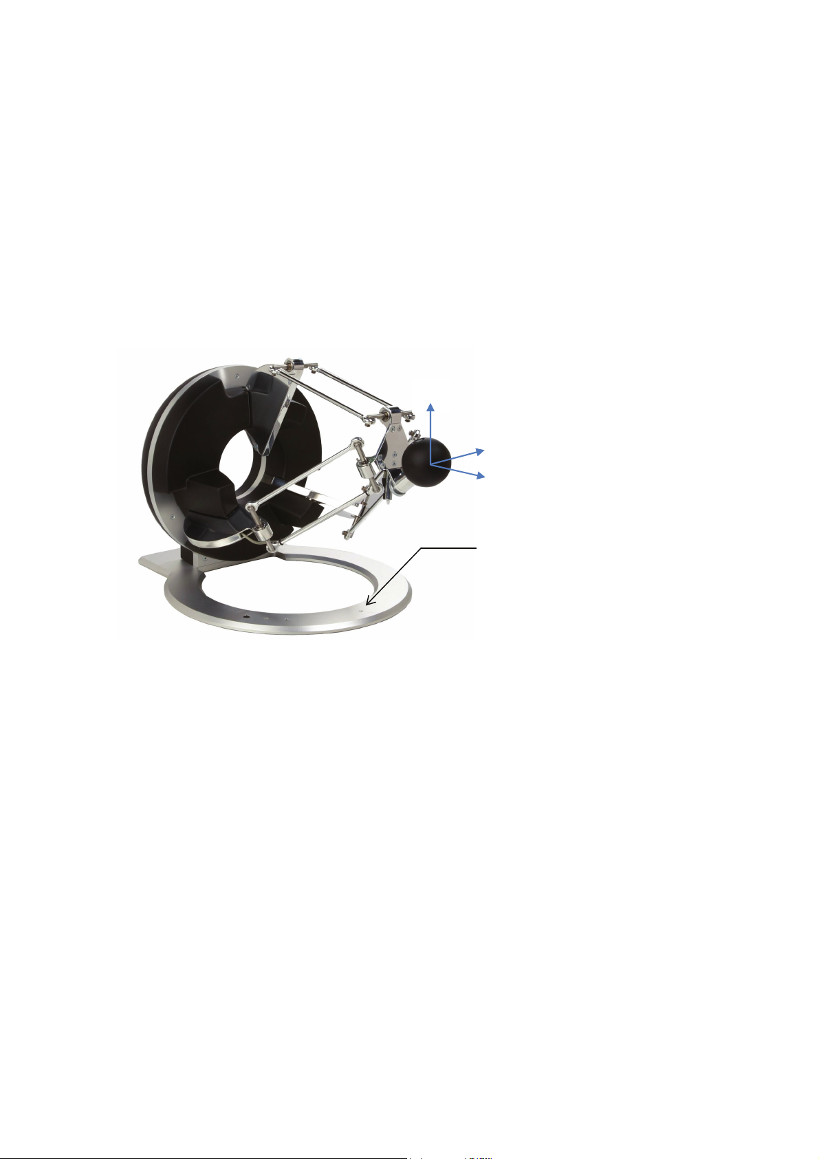
1. device description
10
2
3
2
4
7
146
11
1
12
1
13
589
1. base plate 8. status LED
2. control unit 9. force LED
3. arms 10. programmable button
4. end-effector 11. power switch
5. force button 12. power connector
6. calibration pole 13. USB connector
7. calibration pit 14. tightening knob
7

2. important safety instructions
IMPORTANT
WHEN USING THIS UNIT, BASIC SAFETY PRECAUTIONS
SHOULD ALWAYS BE FOLLOWED TO REDUCE THE RISK
OF FIRE, ELECTRICAL SHOCK, OR PERSONAL INJURY.
1. read and understand all instructions
2. follow all warnings and instructions marked on this unit
3. do not use or place this system near water
4. place the unit securely on a stable surface
5. make sure that the workspace of the omega.x is free of objects
6. do not overload wall outlets and extension cords
this can result in a risk of fire or electrical shock
7. switch off the omega.x when it is not in use
8. to reduce the risk of electrical shock, do not disassemble the omega.x
8

3. setting up the omega.x
IMPORTANT
PLEASE KEEP THE ORIGINAL PACKAGING
ONLY USE THE ORIGINAL PACKAGING FOR STORING OR SHIPPING
3.1 unpacking the device
Before unpacking the device, remove the device stabilizer and the accessories box from within
the box. Carefully remove the device and the end-effector stabilizer from the box, then remove
the end-effector stabilizer.
figure 1 – omega.x shipping box and accessories box
The accessories box contains the power and data cables, as well as the driver and SDK installa-
tion media.
end
-
effector stab
i
lizer
device stabilizer
9


4. configuring the omega.x under Windows
4.1 installing the software
n
s
The installation USB drive must be installed onto your system before connecting the omega.x to
the system. To do this, perform the following steps.
1. plug the Force Dimension USB drive into your system
2. open the \Windows subfolder on the USB drive
3. run setup.exe icon to launch the installation program
4. follow the instructions given by the installation program
4.2 installation descriptio
The installation program creates the following subfolders in :
C:\Program Files\Force Dimension\sdk-<version>
\bin subfolder
This directory contains the demonstration executables and the DLL files required to run the
omega.x software. The required DLL files are also copied to the Windows system folder during
the installation.
\drivers subfolder
This directory contains the USB and PCI drivers required to operate your device.
\examples subfolder
This directory contains the demonstration programs. Example applications described in section
7.4 and come with their full source code.
\doc subfolder
All documentation files and notices are located in that directory.
\manuals subfolder
All hardware user manuals are located in that directory.
\lib,\include subfolders
These directories contain the files required to compile you application with the Force Dimension
SDK. Please refer to the on-line programming manual for more information.
4.3 installing the driver
USB drivers
The omega.x requires the Force Dimension USB driver. These drivers are installed automatically
and no additional step is required.
11

5. configuring the omega.x under Linux
5.1 installing the software
n
s
The Force Dimension development folder must be installed onto your system before the omega.x
can be used. To do this, perform the following steps:
1. plug the Force Dimension USB drive into your system
2. decompress the sdk-<version>.tar.gz file from the drive \Linux subfolder to the de-
sired location (typically your home folder) by running the following command within the tar-
get folder:
tar –zxvf sdk-<version>.tar.gz
3. this will create a sdk-<version> development folder in the target location
5.2 installation descriptio
The development folder contains the following directories:
\bin subfolder
This directory contains the demonstration executables and the binary files required to run the
omega.x software.
\examples subfolder
This directory contains the demonstration programs. Example applications described in section
7.4 and come with their full source code.
\doc subfolder
All documentation files and notices are located in this subfolder.
\manuals subfolder
All hardware user manuals are located in that directory.
\lib,\include subfolders
These directories contain the files required to compile you application with the Force Dimension
SDK. Please refer to the on-line programming manual for more information.
5.3 installing the driver
The Linux version of the Force Dimension SDK requires the development packages for the li-
busb-1.0 and freeglut to be installed on your Linux distribution.
12

6. configuring the omega.x under Mac OS X
6.1 installing the software
n
s
The Force Dimension development folder must be installed onto your system before the omega.x
can be used. To do this, perform the following steps:
1. plug the Force Dimension USB drive into your system
2. open the sdk-<version>.dmg file from the drive \Mac OS subfolder and extract the sdk-
<version> folder to the desired location (typically your home folder)
3. this will create a sdk-<version> development folder in the target location
6.2 installation descriptio
The development folder contains the following directories:
\bin subfolder
This directory contains the demonstration executables and the binary files required to run the
omega.x software.
\examples subfolder
This directory contains the demonstration programs. Example applications described in section
7.4 and come with their full source code.
\doc subfolder
All documentation files and notices are located in this subfolder.
\manuals subfolder
All hardware user manuals are located in that directory.
\lib,\include subfolders
These directories contain the files required to compile you application with the Force Dimension
SDK. Please refer to the on-line programming manual for more information.
6.3 installing the driver
The Apple version of the Force Dimension SDK uses Apple’s native USB drivers, which are in-
cluded in Mac OS X 10.4 and higher. No further installation is required.
13
7. using the omega.x
7.1 device geometry
omega.x translation axis
The position of the end-effector can be read from the controller. The system converts the en-
coder values into (X, Y, Z) coordinate, expressed in IUS (metric) unit. Figure 2 shows the coordi-
nate system. The actual origin of the coordinates system (0,0,0) is located on a virtual point at
the center of the workspace. The calibration pit places the device at the (0.019, 0.0, - 0.074) lo-
cation.
Y
X
Z
calibration coordinates
(0.019, 0.000, - 0.074)
figure 2 – coordinate system
14

omega.6 and omega.7 extensions (optional)
The omega.6 and omega.7 provide a rotational structure. Rotation information can be retrieved
as a reference frame expressed by a 3x3 rotation matrix:
figure 3 – reference frame of the omega.6 and omega.7:
z
x
y
z
y
x
15

7.2 operating the omega.x
status indicators
The status LED displays the status of the system.
>LED OFF the system is off
>LED ON the system is ready
>LED BLINKING (fast) the system requires calibration
>LED BLINKING (slow) the omega.6 extension requires calibration
While the status LED is ON, it is possible to read the position of the end-effector, but no forces
can be applied. Forces must be enabled by pressing the force button. When the forces are en-
abled, the force LED is turned ON. Forces can be disabled by pressing the force button again.
features
calibration –calibration is necessary to obtain accurate, reproducible localization of the end-
effector within the workspace of the device. The omega.x is designed in such a way that there
can be no drift of the calibration over time, so the procedure only needs to be performed once
when the device is powered on.
The calibration procedure consists in placing the calibration pole in the dedicated calibration
pit. The device detects when the calibration position is reached and the status LED stops blink-
ing. Figure 4 illustrates the calibration procedure. After the initial calibration described above,
the LED will stop blinking (omega.3).
figure 4 – calibration procedure
On the omega.6 and omega.7 (optional), the LED will blink at a slower frequency, indicating that
the rotational structure is usable but not fully calibrated. To fully calibrate the omega.6 and
omega.7 extensions, each of the three rotation axis and the grasping axis of the omega.7 must
be moved by hand to their respective end-stops once. When the device has reached all end
stops, the LED stops blinking and the device is fully calibrated.
16

gravity compensation – to prevent user fatigue and to increase accuracy during manipulation,
the omega.x features gravity compensation. When gravity compensation is enabled, the weights
of the arms and of the end-effector are taken into account and a vertical force is dynamically ap-
plied to the end-effector on top of the user command. Please note that gravity compensation is
computed on the host computer, and therefore it only gets updated whenever a force command
is sent to the device by the application. Gravity compensation is enabled by default and can be
disabled via the Force Dimension SDK.
forces - by default, when an application opens a connection to the device, the forces are dis-
abled. Forces can be enabled or disabled at any time by pressing the force button.
brakes – the device feature electromagnetic brakes that can be enabled via software. The brakes
are on by default when the forces are disabled, and can be enabled automatically by the control
unit in some cases. When the brakes are on, a viscous force is created that prevents rapid
movement of the end-effector. Also, enabling the brakes via the Force Dimension SDK simulta-
neously disables the forces.
end-effector tightening knob (omega.3) – the orientation of the end-effector can be adjusted by
means of the tightening knob.
17

safety features
The omega.x features several safety features designed to prevent uncontrolled application of
forces and possible damage to the device. These safety features can be adjusted or disabled via
a protected command in the Force Dimension SDK.
IMPORTANT
PLEASE NOTE THAT THE WARRANTY MAY NOT APPLY
IF THE SAFETY FEATURES HAVE BEEN OVERRIDEN.
When a connection to the device is made from the computer, the forces are automatically dis-
abled to avoid unexpected behaviors. The user must press the force button to enable the forces.
This feature cannot be disabled.
If the control unit detects that the velocity of the end-effector is higher than the programmed
security limit, the forces are automatically disabled and the device brakes are engaged to pre-
vent a possibly dangerous acceleration from the device. This velocity threshold can be adjusted
or removed via the Force Dimension SDK. Please refer to the on-line programming manual for
more information.
18

7.3 running the HapticDesk program
Under Windows, the HapticDesk is available as a test and diagnostic program.
HapticDesk allows the programmer to:
>list all Force Dimension haptic devices connected to the system
>test each device position reading
>test each device force/torque capability
>test each device auto-calibration procedure
>read each device status
>read any device encoder individually
figure 5 – HapticDesk test and diagnostic program
19

7.4 running the demonstrations programs
Two demonstration programs can also be used to diagnose the device. The source code and an
executable file for each of the demonstration programs are provided in two separate directories
named \gravity and \torus.
Once the system is setup, we suggest running gravity to check that everything is working
properly and to evaluate your system's performance independently of the graphics rendering
performance. torus will allow you to test the combined performance of haptics and graphics
rendering.
gravity example
This example program runs a best effort haptic loop to compensate for gravity. The appropriate
forces are applied at any point in space to balance the device end-effector so that it is safe to let
go of it. The refresh rate of the haptic loop is displayed in the console every second.
figure 6 – gravity example
20
This manual suits for next models
3
Table of contents
Popular Recording Equipment manuals by other brands


STARVILLE
STARVILLE DMX Joker V2 1024 Box quick start guide

Focusrite Audio Engineering
Focusrite Audio Engineering BASS STATION II user guide

Lorex
Lorex LW2300 SERIES quick start guide

Telesystems
Telesystems ?AVR-H.264 Operation manual

Technics
Technics SH-8017 Service manual

Pleora Technologies
Pleora Technologies iPORT NTx-Mini-S user guide