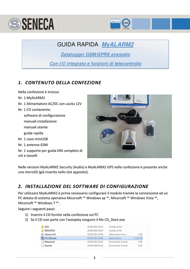
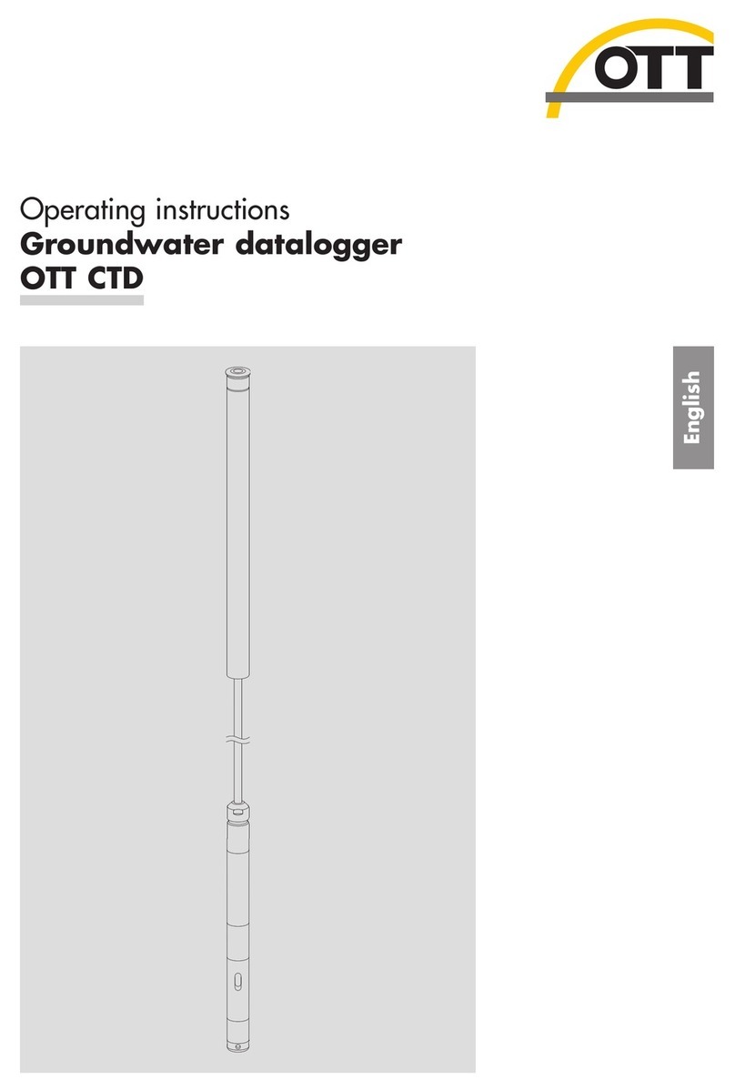
Intab PC-Logger 3100i Operating instructions

How to use
PC-logger 3100i
and
accessories
INTAB Interface-Teknik AB
www.intab.se


3100i-eng.doc iii
CONTENTS
BASIC UNIT ................................................................................................................5
1 AN OVERVIEW ................................................................................................5
1.1 General .........................................................................................................5
1.2 ”On-line” measurements .............................................................................6
1.3 ”Off-line” measurements.............................................................................6
2 DISPLAY AND KEYS.......................................................................................7
2.1 CLOCK..............................................................................................................7
3 STORAGE CAPACITY....................................................................................8
3.1 Storage capacity in your computer..............................................................8
3.2 Storage capacity in the ”3100i”...................................................................9
4 POWER SUPPLY............................................................................................10
5 INPUTS -RANGES.........................................................................................11
5.1 Preset ranges ..............................................................................................12
5.2 Software Switchable Ranges......................................................................12
5.3 RANGES AND THEIR RESOLUTION .................................................................13
5.4 Temperature measurements - T/C:s..........................................................13
6 CONNECTORS ...............................................................................................16
6.1 Power ..........................................................................................................16
6.2 Computer ....................................................................................................16
6.3 Connecting Sensors and Transducers.......................................................17
7 MISCELLANEOUS ........................................................................................23
7.1 Reset............................................................................................................23
7.2 Program......................................................................................................23
8 TECHNICAL SPECIFICATIONS.................................................................24
8.1 Analog Data................................................................................................24
8.2 Storage Memory .........................................................................................26
8.3 Computer communication..........................................................................26
8.4 Commands..................................................................................................26
8.5 Power ..........................................................................................................27
8.6 Mechanical specifications..........................................................................27
8.7 Environmental conditions..........................................................................27
OPTION: DIGITAL I/O AND PULSE COUNTERS............................................29
1 AN OVERVIEW ..............................................................................................29
1.1 Digital Outputs ...........................................................................................29
1.2 Digital Inputs..............................................................................................30
2 COUNTERS .....................................................................................................31
2.1 Reset mode..................................................................................................31
2.2 Normal mode..............................................................................................31
3 CONNECTIONS..............................................................................................32
3.1 Digital outputs............................................................................................33
3.2 Digital inputs..............................................................................................33
4 TECHNICAL DATA (@ 25C +/-10C)............................................................35
4.1 Digital Outputs ...........................................................................................35
4.2 Digital Inputs..............................................................................................35
4.3 Auxiliary Power..........................................................................................36

INTAB Interface-Teknik AB
iv
OPTION : CONSTANT CURRENT SOURCES....................................................37
1 AN OVERVIEW ..............................................................................................37
1.1 Temperature Measurements with Pt-100 Sensors ....................................38
2 DESCRIPTION................................................................................................39
3 CONNECTING SENSORS.............................................................................40
3.1 Screw Terminals.........................................................................................40
3.2 Measurement Methods...............................................................................41
4 TECHNICAL DATA.......................................................................................44
OPTION : MODEM PORT......................................................................................45
1 DATA FORMAT..............................................................................................45
2 CONNECTOR STANDARD...........................................................................45
3 ”3100I”MODEM SETTINGS ........................................................................46
4 COMPUTER MODEM SETTINGS.......................................................................47
INDEX.........................................................................................................................48

5
BASIC UNIT
BASIC UNIT
1 AN OVERVIEW
1.1 General
The PC-logger model 3100i finds its use mostly in long term recording of
process signals and/or temperatures. Possible input ranges are +/-50mV,
+/-100mV, +/-1000mV, +/-10V, 20mA and thermoelectric voltages.
Very high resolution (25 000 steps or divisions) and excellent accuracy
(better than 400ppm) makes it possible to achieve remarkably good results
from the most difficult measuring task.
A 3100i together with software and a personal computer constitute a powerful
data acquisition/recording system. It is an excellent and up to date substitute
for strip chart recorders.
The rugged case lets you apply the ”3100i” in very harsh environments.
Noteworthy are the rubber edges that spare your table tops.
The scope of this manual is to enable the user to correctly connect transducers
and use the ”3100i” off-line.
How the ”3100i” is handled using our software and a PC is explained in the
program manuals and by the programs themselves by their user-friendly and
self-explanatory menus.
Those users who intend to write their own programs to collect data with the
”3100i” are recommended to study the special ”Command manual” that
describes available commands and their syntax.
In order to conserve battery capacity when the mains fail, the ”3100i” ”falls
asleep” when it hasn’t been called upon for about 2 minutes. It is woken by
incoming RS-232 serial data or by pressing the C key (see 2.).
Correct time is always supplied by our software.
On-line recordings are ”timed” by the computer.
Transferring off-line parameters will also supply correct time to the logger
RTC.
Check your computer clock, should the recording time information be
incorrect.

6 INTAB Interface-Teknik AB
1.2 ”On-line” measurements
On-line measurements are performed with the ”3100i” connected to the
computer’s RS-232 port. Measurements can in this mode be monitored in real-
time on the computer’s display. Incoming data are continuously transferred to
disk.
1.3 ”Off-line” measurements
Off-line recordings are only possible with units that are equipped with
“Display and 64k data memory” and optionally, “expansion memory”.
Off-line measurements should be preceded by the transferral of measurement
parameters from the computer to the ”3100i”.
These parameters contain, among others (see program manual), information
about time and date, measurement interval and which channels are to be
active.
These parameters are effective until a new set is downloaded. The ”3100i”
can, after downloading of the parameters, be disconnected from the computer
and started with the help of the keys next to the LCD (see 2.).
After all measurements are completed the ”3100i” is again connected to a
computer for transferral of collected data.

7
BASIC UNIT
2 DISPLAY AND KEYS
The LCD (Liquid Crystal Display) with adjacent keys are supplied with all
3100i:s that are equipped with internal memory.
This display and key combination is indispensable when making off-line
recordings. You indicate which function you want using the up/down arrows
and then confirm your choice with the OK-key.
The MULTIMETER is used to check transducer connections and function
before recording is started. You scroll up and down among the channels using
the up/down arrow keys. Automatic scrolling is started with the key under the
logo. A new channel is then shown every three seconds Try this feature by
pressing the ”intab°” logo.
RECORD is selected when you intend to collect data. Verify your choice with
”OK”. See illustration below.
Starting a new recording will delete the previous one.
Don’t forget to transfer data to the computer between recordings.
RECORD will also tell you ”Recording on”, if it is.
See Option: Modem Port for information on Modem Baudrate.
2.1 Clock
Logger time and date are shown in the display. They are set every time
recording parameters are supplied by the software. Correct time and date are
transferred from the computer together with off-line recording parameters.
The clock is only used by off-line recordings. Start time and sampling interval
(∆t)are used by the software to calculate data point time and date.

8 INTAB Interface-Teknik AB
3 STORAGE CAPACITY
The number of measurements that can be stored by the ”3100i” and/or
computer is dependent on the size and type of memory used.
The longest possible duration of a recording is a function of the number of
channels that are active, sampling rate and the size of the storage medium.
A discussion of how the maximum length of a recording can be calculated
from known parameters follows below.
It is assumed that recordings are made using software supplied by INTAB.
3.1 Storage capacity in your computer
The data storage capacity of your computer depends on the amount of free
space on the disk that is to store your measurements.
Modern computers usually have such large disks that the storage capacity is
enough for any recording task.
The only “problem” may be that it is too easy to over-sample, resulting in
cumbersome amounts of data.

9
BASIC UNIT
3.2 Storage capacity in the ”3100i”
The storage capacity of the ”3100i” is dependent on memory size.
Three sizes of memory can be supplied: 64k, 576k or 1088k.
Every value stored uses two bytes, making it easy to calculate available
recording time.
(Note that units without memory can only be used in on-line applications.)
An example: having 64k memory you want to measure four channels 10 times
every minute. The interval is then 6 seconds.
The formula will be: 6*64 000/2*4=48 000 seconds (or more than 13 hours).
The internal memory of the ”3100i” will only store one recording at a time.
Starting a new recording will erase the previous one. Recordings have to be
transferred to your computer before loading new parameters or starting new
measurements.
There is no limit to the number of times the same recording can be transferred
to the computer.
Measurement data will also not be lost if the internal batteries run down. A
backup lithium battery will retain data for more than 10 years.
Rotating (or endless) memory is described in the program manual.

10 INTAB Interface-Teknik AB
4 POWER SUPPLY
The ”3100i” is normally powered by the supplied mains adapter.
The ”3100i” is fitted with internal rechargeable batteries. They will give the
user at least two hours of measuring time without mains supply. The batteries
are trickle-charged when the mains adapter is connected.
There is no danger of overcharging the batteries. They should be left on
charge to keep them ready to use at all times. This will also prolong the
life of the batteries.
The internal accumulators may be disconnected from the rest of the circuitry
by removing a jumper on the analogue board.
< Jumper
Completely discharged batteries may at first take up to about 15 minutes to
charge to a point where the ”3100i” again will be operational. Two days of
charging should be enough to bring them up to full capacity.
Some applications require the ”3100i” to be powered by other sources.
Use a cable fitted with a TA3F (Switchcraft) connector to connect to, for
example, a car battery.
Don’t use sources supplying more than 15 Volts as this is the maximum
allowed.
When the mains fails or is disconnected, the ”3100i” will ”fall asleep” about
two minutes after the last command or keystroke has been entered. This
feature saves your rechargeable batteries for when they are needed.
Incoming serial (RS-232) commands or pressing the C-key will wake the
”3100i”.
Recordings will of course proceed uninterrupted. Long sampling intervals
(>10s) will allow the logger to fall asleep between samplings thus conserving
battery power.

11
BASIC UNIT
5 INPUTS - RANGES
All analogue channels are DIFFERENTIAL. They measure the voltage
between - and GND and the voltage between + and GND. The subtraction is
then performed internally.
NOTE
The GND is logger reference or signal ground. It has nothing in common with
other system or safety grounds unless the operator interconnects them.
When we in the following pages refer to GND or ground we only mean the
logger ground. NOTHING ELSE!
Standard inputs are balanced. This makes them very insensitive to noise if the
signal source is correctly connected. A signal cable consisting of a twisted pair
can be very long if the lowest potential of the source is connected to ground
via a separate cable.
The input ranges are set, adjusted and calibrated at factory prior to shipment.
Two main types of inputs are available: preset channels and ”Software Range
Switchable”.
Preset channel units are individually ”ranged”, adjusted and calibrated, and
cannot be altered by the user. They have to be returned to factory for
modification.
”3100i”:s with Software Range Switching has four programmable ranges per
channel. The range (or Full Scale Reading) of each channel is selected, or
programmed, together with the rest of the ”parameters” before the recording is
started.

12 INTAB Interface-Teknik AB
5.1 Preset ranges
The channels of ”3100i”:s are in groups of eight.
The channels in such a group may be individually set to one of the available
ranges.
Available ranges are +/-10V, +/-1000mV, +/-100mV, +/-50mV, 20mA and
thermo emf:s.
Temperature inputs measure thermoelectric voltages. These are then cold
junction compensated and linearized to present a correct value. All
temperature channels are presumed to have the same type of T/C connected.
”3100i” has, as standard, linearization tables for types B, E, J, K, R, S, T and
N.
All inputs (channels) have at least 25000 divisions. A division is the smallest
discernible change in input signal. The resolution of an input can be expressed
as FSR divided by the no. of divisions. Two examples:
a) A 10V input has a resolution of 10V/25000= ca 0.4mV.
b) A 50mV input has a resolution of 50mV/25000= ca 2µV.
5.2 Software Switchable Ranges
The ”3100i” can, as an option, be fitted with software switchable input ranges.
This versatile option can be compared to the switch on an ordinary multimeter
with the difference that the user has to press a number of keys on the computer
instead of the meter.
Channels are individually programmable. T/C linearization is individually
selectable so that channels may even have different types of thermocouples
connected.

13
BASIC UNIT
5.3 Ranges and their Resolution
An ”3100i” is especially suited for monitoring process type signals and still
has the very sensitive 50mV range available.
The ranges and their resolutions are:
RANGE RESOLUTION
+/- 10V 0.4 mV
+/- 1000mV 40µV
+/- 100mV 4µV
+/- 50mV 2µV
An input set to the 50mV range can measure temperature with a resolution of
0.1°C using T/C:s type K. The temperature range will in this case be -100 to
+1200 °C.
Each channel has a shunt resistor that is connected across the input via a
switch on the analogue board adjacent to the screw terminals. This resistor has
to be switched in manually when current measurements are to be taken (see
6.3.2.).
Range here is 0 - 20mA which resolves the signal to 6µA.
Note that 4 - 20mA signals are beautifully transformed into correct magnitude
and unit by the ”transform” function of the software.
NOTE that the shunt resistor will overheat if subjected to more than
80mA.
5.4 Temperature measurements - T/C:s
The ”3100i” is specially adapted for temperature measuring using
thermocouples.
Thermocouples are active sensors that don’t require powering to supply a
signal. They are non-linear but are linearized by the ”3100i”.
A thermocouple is in its simplest form a pair of wires of dissimilar materials
that are soldered together at one end. The other end is connected to the two
screw terminals of a channel. The difference in temperature between the
soldered end and the screw terminals gives rise to a voltage that can be
measured.
This voltage is different for different thermocouple materials so tell the
software which type(s) you are using!

14 INTAB Interface-Teknik AB
5.4.1 Ranges and linearization
Different types of thermocouples have differing levels of output. They
therefore have differing fields of application most often depending on the
temperature range to be measured.
What two materials make up the couple may also be of a certain importance.
We will however, have to assume that this is known to the user.
Below is a short summary of the properties of the most common types of
thermocouples. It is included to help in selecting type and range for your
application.
”K” is the most common type.
”Cold Junction” = 0°C
TYPE mV at
200°C mV at
600°C mV at
1200°C
MAX temp °C
K 8.137 24.902 48.828 1370
N 5.912 20.609 43.836 1300
J 10.777 33.096 ---------- 760
T 9.286 --------- ---------- 400
S 1.440 5.237 11.947 1760
R 1.468 5.582 13.224 1760
Thermocouples are non-linear. This is corrected by the internal program of the
”3100i”.
Thermoelectric voltage is measured (in mV) and then adjusted for the cold
junction temperature according to the type specified. This adjusted voltage is
then used as input variable to a linearizing table. The table (one for each
thermocouple type) is constructed so that its contribution to the measurement
error is negligible.

15
BASIC UNIT
5.4.2 Cold Junction Compensation
When using thermocouples to measure temperature it is almost always
necessary to know the temperature of the ”cold junction”. Thermoelectric
voltage has to be ”adjusted” with respect to this temperature.
Thermoelectric voltage is the result of the temperature difference between
the cold junction and the hot junction.
A solid state temperature sensor has been placed centrally in the screw
terminal area of the analogue board. Its temperature is automatically sampled
every time a temperature measurement is taken. All temperature
measurements are thus compensated for the actual temperature of the
terminals themselves.
Some precautions have to be taken if the ”3100i” is exposed to rapid
temperature gradients. Since temperature is measured in one point only, a
gradient from one side of the unit to the other may cause misreadings.
By giving the unit time to reach a stable temperature before recordings are
started and by protecting it from sudden changes of ambient temperature a
very high degree of accuracy can be achieved.

16 INTAB Interface-Teknik AB
6 CONNECTORS
6.1 Power
Power is applied through a TA3F (Switchcraft) female connector connected as
follows :
Pin 1 : + 12-15VDC
2 : 0V
3 : + 20-28VDC (this is an alternative to pin 1)
6.2 Computer
”3100i” connects to a serial port of the computer using the supplied spiral
cable.
The 15 pin D-SUB connector has the following pin-outs:
pin 2 : Tx
pin 3 : Rx
pin 5 : CTS
pin 6 : DTR
pin 7 : GND
Leave the rest of the pins unconnected or damage may result!!
Typical Computer to ”3100i” cables:

17
BASIC UNIT
6.3 Connecting Sensors and Transducers
Sensors or Transducers are connected to the screw terminals that are
accessible under the lid.
The terminals are detachable and can be tilted 90°. Terminal assignment and
polarity can be seen in the figure below.
Use the 16 hole bracket as strain-relief for transducer cables. You can use a
tie-wrap or simply thread the wire trough two holes.
21
22
23
24
13
14
15
16
DIFF GND
5
6
7
8
DIFF GNDDIFF GND
+
-
-
CHANNEL 7
CHANNEL 8
-
+
-
CHANNEL 15
CHANNEL 16
+
-
-
CHANNEL 23
CHANNEL 24
U I
13
14
15
16
U I
12
10
11
U I
21
22
23
24
9
+
-
+
-
+
CHANNEL 21
CHANNEL 22
+
-
+
-
+
CHANNEL 13
CHANNEL 14
+
-
+
-
+
CHANNEL 5
CHANNEL 6
GND GND
U I
17
18
19
20
+
-
-
CHANNEL 20
-
+
-
CHANNEL 12
+
-
-
CHANNEL 4
+
-
+
-
CHANNEL 1
CHANNEL 2
CHANNEL 3
+
-
+
-
CHANNEL 9
CHANNEL 10
CHANNEL 11
+
-
+
-
CHANNEL 17
CHANNEL 18
CHANNEL 19
U I
8
7
6
5
4
3
U I
17
18
19
20
2
1
+
9
10
11
12
DIFF GND
+
1
2
3
4
DIFF GND
+
DIFF GND
Switches for choice
between single ended
(GND) or differential
inputs
Software Range-
Switchable units have
these switches.
In position ”I” they
connect a shunt
resistor across the
input for current
measurements.
Note the irregular
numbering of the
switches.

18 INTAB Interface-Teknik AB
Connecting Sensors and Transducers (cont.)
The following information also applies to units fitted with jack panels.
The panel is only an extension of the screw terminals. GND is also made
available through two black banana jacks at the logger end.
There are a few basic rules that have to be followed when connecting sensors
and transducers.
Let us first take a look at a block diagram of the inputs. They are differential
and, as can be seen, have no internal connection to signal ground.
Input block diagram
Differential channels measure (as the name implies) the difference in voltage
between the + and - input in relation to signal ground.
Another way of saying this is that each channel measures TWO voltages:
- a) between GND and minus and
- b) between GND and plus.
- The difference is then calculated internally and presented as the channel
value.
By ”GROUND” we mean the internal signal ground of the ”3100i”. It has
nothing to do with safety or system ground of other systems unless you
interconnect them.
Also note that the ”3100i” analogue ground is the same electrical point as
the RS-232 signal return AND the 0V of the power supply input
connector.

19
BASIC UNIT
Connecting Sensors and Transducers (cont.).
The impedance between the positive and negative inputs to ground is of the
order of several MΩ. They must therefore never be allowed to float outside
the specified common mode range, but must be referenced to ground in some
way.
Use the miniature switches to set up the channels as single ended inputs.
These switches ground the negative input of corresponding channels.
Before doing this, you have to make sure that no potential exists between the
negative outputs of your transducers as his could burn out your wiring or
worse.
You must also be careful not to introduce ground loops in your signal paths.
To maintain the validity of your measurements you have to take the common
mode range into account.
Common mode range is +/-10V for most ranges.
LOGGED
SIGNAL
+
-CHANNEL
GND (ref)
MAX 10V
COMMON MODE SIGNAL
AAC-2 : "COMMON MODE"
The inputs will not be damaged by voltages above this as long as they are
within 30V off signal ground.
The following sections of this manual will provide some examples of how
transducers can be connected.
NOTE that these instructions also are valid for units with jack panels. You
have to open the lid to make those channels single ended that should be single
ended.
”3100i” signal ground is here also available as two black banana jacks on one
of the sides of the casing.
The jack panel must be looked upon as a device external to the logger itself. It
is built into the logger casing only for practical reasons.

20 INTAB Interface-Teknik AB
6.3.1 Thermocouples
Thermocouples can be connected in two ways (see fig. below). Which one you
choose will depend on your particular application. As a general rule it would
appear to be more practical to connect the negative input to ground by setting
the switch in the single-ended position. Never leave any transducers without
some type of connection to ground.
The two methods can be combined but you have to make sure that your
ground leads don’t carry any current or connect to the same point from two
directions. Ground leads that carry current will, at best, ruin your
measurements. At worst it will burn out your wiring.
Avoid these problems by using a one-point grounding scheme.
1) T/C ”hot” junction in contact with conducting object.
+
-
+
-
DIFF
1
2
GND
Connect object to signal
GND
Connect your T/C:s
Place switch in position
”DIFF”
2) T/C ”hot” junction isolated from measured object.
+
-
+
-
1
2
GNDDIFF
Do NOT connect object
to signal GND
Connect your T/C:s
Place switch in position
”GND” making them
single ended
Table of contents
Other Intab Data Logger manuals
Popular Data Logger manuals by other brands
Onset
Onset Hobo UX90-001 Series manual
EDGEMATRIX
EDGEMATRIX Edge AI Box Light user manual
Extech Instruments
Extech Instruments 42280-NIST user guide

Dewetron
Dewetron DEWE2-M7s Technical reference manual
Onset
Onset HOBO Pendant MX Temp manual
Huawei
Huawei FusionModule 1000A20 Initial Configuration Parameter Manual
