manuals.online logo
Brands
  1. Home
  2. •
  3. Brands
  4. •
  5. sauermann
  6. •
  7. Data Logger
  8. •
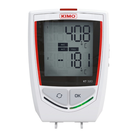
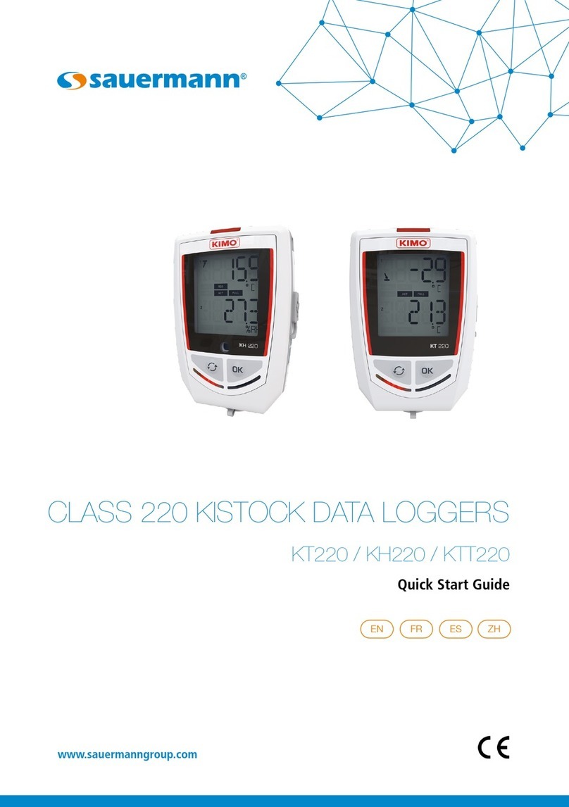
  9. sauermann 220 Series User manual

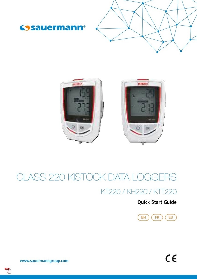
sauermann 220 Series User manual

TABLE OF CONTENTS
1 SAFETY INSTRUCTIONS.................................................................................................................................................4
1.1 Precautions...........................................................................................................................................................4
1.2 Symbo s................................................................................................................................................................4
2 DEVICE COMPONENTS..................................................................................................................................................5
2.1 Use.......................................................................................................................................................................5
2.2 App ications..........................................................................................................................................................5
2.3 Se ection...............................................................................................................................................................5
2.4 Layout.................................................................................................................................................................. 5
2.5 Buttons.................................................................................................................................................................6
2.6 LEDs..................................................................................................................................................................... 6
2.7 Connections..........................................................................................................................................................6
2.8 Mounting..............................................................................................................................................................6
3 TECHNICAL FEATURES..................................................................................................................................................7
3.1 Technica data.......................................................................................................................................................7
3.2 Housing................................................................................................................................................................8
3.3 Directive: FCC part 15........................................................................................................................................... 8
3.4 Optiona probes and cab es...................................................................................................................................9
3.4.1 KT 220 and KH 220 optiona probes, cab es and ammeter c amps...................................................................9
3.4.2 KTT 220 optiona thermocoup e probes........................................................................................................10
3.5 Connect a probe on the universa input................................................................................................................10
3.6 Connect a probe on the thermocoup e input.........................................................................................................10
3.7 Dimensions.........................................................................................................................................................11
3.7.1 Devices.......................................................................................................................................................11
3.7.2 Wa mount................................................................................................................................................. 11
3.8 Warranty period...................................................................................................................................................11
4 USE OF THE DEVICE....................................................................................................................................................12
4.1 Disp ay................................................................................................................................................................ 12
4.2 Functions of LEDs................................................................................................................................................12
4.3 Configuration, data ogger down oad and data processing with the KILOG software..............................................13
4.4 Functions of buttons............................................................................................................................................13
4.4.1 Groups organization....................................................................................................................................15
4.4.2 Measurements scro ....................................................................................................................................15
4.5 PC communication..............................................................................................................................................15
5 MAINTENANCE........................................................................................................................................................... 16
5.1 Rep ace the battery.............................................................................................................................................16
5.2 Device c eaning...................................................................................................................................................16
5.3 Safety ock wa mount with pad ock....................................................................................................................16
6 CALIBRATION............................................................................................................................................................. 17
7 ACCESSORIES.............................................................................................................................................................17
8 TROUBLESHOOTING.................................................................................................................................................... 17
1 SAFETY INSTRUCTIONS
1.1 Precautions
P ease a ways use the device in accordance with its intended use, and within the parameters described in the technica
features page 7 in order not to compromise the protection ensured by the device.
Changes or modifications not express y approved by Sauermann cou d void the user’s authority to operate the equipment.
1.2 Symbols
For your safety and in order to avoid damage to the device, p ease fo ow the procedures described in this user
manua and carefu y read the notes that are preceded by the fo owing symbo :
The fo owing symbo wi a so be used in this user manua :
P ease carefu y read the information notes indicated after this symbo .
4
SAFETY INSTRUCTIONS
2 DEVICE COMPONENTS
2.1 Use
The c ass 220 data oggers measure severa parameters:
•KT 220: interna measurement of temperature and one externa universa input for probe
•KH 220: interna measurement of temperature, humidity and ight and one externa universa input for probe
•KTT 220: thermocoup e temperature measurement with two thermocoup e externa inputs
This c ass of devices is avai ab e with or without disp ay.
The communication between the device and the computer is carried out via USB cab e with a fema e micro-USB connector.
2.2 Applications
The data oggers are idea for the monitoring of severa
parameters (temperature, humidity, ight, current, vo tage, pu se,
re ative pressure). They ensure traceabi ity in the food industry
environment, as we as va idate that industria insta ations are
functioning proper y.
2.3 Selection
Part No. Display Internal sensors External sensors Parameters Number of
recordin points
Number Type Number Type
KT 220 - O P
1 Temperature
1Input for
universa probes*
Temperature, humidity,
current, vo tage, pu se &
water pressure
1,000,000
KT 220 - N
KH 220 - O P
3
Temperature,
humidity &
ight
Temperature, humidity,
current, vo tage, pu se, water
pressure & ight
KH 220 - N
KTT 220 - O P
N/A 2
Inputs for
thermocoup e
probes**
Temperature
KTT 220 - N
*Universa input a ows compatibi ity with mu tip e probes. Reference page 9 for further information.
**Input a ows compatibi ity with thermocoup e probes. Reference page 10 for further information.
2.4 Layout
DEVICE COMPONENTS
5
“Selection” button “OK” button
A arm LED Operating LED
Disp ay
2.5 Buttons
OK button: start and stop the dataset, or switch between scro ing group (see page 13)
Selection button: se ect between va ues in a scro ing group (see page 13)
2.6 LEDs
2.7 Connections
The communication between the device and the computer is carried out via USB cab e and with a fema e micro-USB
connector.
2.8 Mountin
The c ass 220 data oggers are equipped with a magnetic case for easy mounting.
6
DEVICE COMPONENTS
Magnetic mountings
Micro-USB
connector
Universa probe input
KT 220 / KH 220
Micro-USB
connector
2 thermocoup e inputs
KTT 220
Alarm LED Operatin LED
3 TECHNICAL FEATURES
3.1 Technical data
KT 220 KH 220 KTT 220
Units displayed °F, °C, °Ctd, °Ftd, %RH, mV, V,
mA, A, bar1
°F, °C, °Ctd, °Ftd, %RH, ux, fc, mV, V, mA,
A, bar1°F, °C
Resolution
0.1°F, 0.1°C, 0.1%RH, 1 mV,
0.001 V, 0.001 mA, 0.1 A,
0.1 bar
0.1°F, 0.1°C, 0.1%RH, 1 ux, 0.1 fc, 1 mV,
0.001 V, 0.001 mA, 0.1 A, 0.1 bar 0.1°F, 0.1°C
External input Fema e micro-USB connector Fema e micro-USB connector Fema e micro-USB connector
Input for probe 1 universa input21 universa input22 inputs for thermocoup e probes
(K, J, T, N, S)
Internal sensor Temperature Temperature, humidity, ight Temperature
Type of sensor Thermistor (NTC) Thermistor (NTC), capacitive, photodiode Thermocoup e
Measurin ran e
Interna sensor3:
-40 to 158°F
(-40 to 70°C)
Interna sensor3:
Temp.: -4 to 158°F (-20 to 70°C)
Humidity: 0 to 100%RH
Light: 0 to 10,000 ux
K: -328 to 2372°F (-200 to 1300°C)
J: -148 to 1382°F (-100 to 750°C)
T: -328 to 752°F (-200 to 400°C)
N: -328 to 2372°F (-200 to 1300°C)
S: 32 to 3200°F (0 to 1760°C)
Accuracies4
±0.8°F from -4 to 158°F
(±0.4°C from -20 to 70°C)
±1.5°F be ow -4°F
(±0.8°C be ow -20°C)
Temp: ±0.8°F from 32 to 122°F
(±0.4°C from 0 to 50°C)
±1.5°F be ow 32°F or above 122°F
(±0.8°C be ow 0°C or above 50°C)
Humidity5: ±2%RH from 5 to 95%RH
@ 59 to 77°F(15°C to 25°C)
Light: ±10% of reading +10 ux
K, J, T, N: ±0.8°F from 32 to 2372°F
(±0.4°C from 0 to 1300°C)
±(0.3% of the reading +0.8°F) be ow 32°F
(±(0.3% of the reading +0.4°C) be ow 0°C)
S: ±1.1°F (±0.6°C)
Operatin temperature -40 to 158°F
(-40 to 70°C)
-4 to 158°F
(-20 to 70°C)
-4 to 158°F
(-20 to 70°C)
Stora e temperature -40 to 185°F
(-40 to 85°C)
-40 to 185°F
(-40 to 85°C)
From -40 to 185°F
(-40 to 85°C)
Alarm set points 2 a arm set points per channe 2 a arm set points per channe 2 a arm set points per channe
Frequency of
measurement 1 s to 24 h 1 s to 24 h 1 s to 24 h
Battery life 4 years64 years64 years6
Warranty 1 year 1 year 1 year
Directives 2011/65/EU RoHS II; 2012/19/EU WEEE; FCC part 15; UL 61010
1 Some units are avai ab e on y with optiona probes.
2 Universa input a ows compatibi ity with mu tip e probes. Reference page 9 for further information.
3 Other measuring ranges are avai ab e according to the connected probe: see optiona probes and cab es page 9.
4 A accuracies specified in this document were conducted under aboratory conditions and can be guaranteed for measurement carried out in the same conditions, or carried out with
ca ibration compensation.
5 Factory ca ibration to erance: ±0.88%RH; Temperature dependence: ±0.04 x [((T °F -32) x 5/9) -20] %RH (if T≤59°F or T≥77°F) / ±0.04 x (T-20) %RH (if T≤15°C or T≥25°C)
6 On the basis of 1 measurement each 15 minutes at 77°F (25°C).
TECHNICAL FEATURES
7
3.2 Housin
Dimensions 3.67'' x 2.57'' x 1.20'' (93.2 x 65.2 x 30.5 mm)
Wei ht 4 oz (115 g)
Display
2- ine LCD screen (for mode s with disp ay)
Screen: 1.54'' x 1.34'' (39 x 34 mm)
2 indication LEDs (red and green)
Control 1 OK button
1 Se ection button
Material Compatib e with food industry environment
ABS housing
Protection
IP 65: KT 220
IP 54: KTT 220*
IP 40: KH 220
PC communication Fema e micro-USB connector
USB cab e
Battery power supply 1 AA ithium 3.6 V battery
Environmental conditions of use
Non-corrosive or combustib e gases
Hygrometry: in non-condensing condition
Maximum a titude: 6561' (2000 m)
3.3 Directive: FCC part 15
Chan es or modifications not expressly approved by Sauermann could void the user’s authority to
operate the equipment.
This equipment has been tested and found to comp y with the imits for a C ass B digita device, pursuant to part 15 of the
FCC Ru es. These imits are designed to provide reasonab e protection against harmfu interference in a residentia
insta ation. This equipment generates uses and can radiate radio frequency energy and, if not insta ed and used in
accordance with the instruction, may cause harmfu interference to radio communications. However, there is no guarantee
that interference wi not occur in a particu ar insta ation. If this equipment does cause harmfu interference to radio or
te evision reception which can be determined by turning the equipment off and on, the user is encouraged to try to correct
interference by one or more of the fo owing measures:
•Reorient or re ocate the receiving antenna.
•Increase the separation between the equipment and receiver.
•Connect the equipment into an out et on circuit different from that to which the receiver is connected.
•Consu t the dea er or an experienced radio/TV technician for he p.
8
TECHNICAL FEATURES
* With all the thermocouple probes connected.
3.4 Optional probes and cables
3.4.1 KT 220 and KH 220 optional probes, cables and ammeter clamps
Part No. Description Measurin ran es Accuracies Ima e & dimensions
Temperature and humidity probe
KTHA RH / temp. stub probe
0 to 100% RH
-4 to 158°F
(-20 to 70°C)
±2%RH from 5 to 95%RH @ 59°F to 77°F
(15 to 25°C)
Temp: ±0.9°F from 32 to 86°F
(±0.5°C from 0 to 30°C)
±(-2% of the measured va ue +1.8°F) be ow 32°F
(±2% of the measured va ue ±0.6°C be ow 0°C)
±1.5% of reading above 86°F
(±1.5% of the measured va ue above 30°C)
2.56'' (65 mm)
KTHD RH / temp. remote probe
5.12'' (130 mm)
NTC Thermistor temperature probe
KSI-50 2" immersion probe
(IP 65)
-40 to 248°F
(-40 to 120°C)
±0.8°F from -4 to 158°F
(±0.4°C from 20 to 70°C)
±1.5°F (±0.8°C) beyond Ø0.24'' x 1.97'' (Ø6 x 50 mm)
KSI-150 6" immersion probe
(IP 65)
-40 to 248°F
(-40 to 120°C)
±0.8°F from -4 to 158°F
(±0.4°C from 20 to 70°C)
±1.5°F (±0.8°C) beyond Ø0.24'' x 5.9'' (Ø6 x 150 mm)
KSA-150 Ambient air probe -40 to 248°F
(-40 to 120°C)
±0.8°F from -4 to 158°F
(±0.4°C from 20 to 70°C)
±1.5°F (±0.8°C) beyond Ø0.24'' x 5.9'' (Ø6 x 150 mm)
KSF-2 Wire probe -4 to 212°F
(-20 to 100°C)
±0.8°F from -4 to 158°F
(±0.4°C from 20 to 70°C)
±1.5°F (±0.8°C) beyond Ø0.12'' (Ø3 mm)
KSPP-150 Penetration probe
(IP 68)
-40 to 248°F
(-40 to 120°C)
±0.8°F from -4 to 158°F
(±0.4°C from 20 to 70°C)
±1.5°F (±0.8°C) beyond Ø0.12'' x 5.9'' (Ø3 x 150 mm)
KSP-150 Penetration probe
(IP 65)
-40 to 248°F
(-40 to 120°C)
±0.8°F from -4 to 158°F
(±0.4°C from 20 to 70°C)
±1.5°F (±0.8°C) beyond Ø0.18'' x 5.9'' (Ø4.5 x 150 mm)
KCV-220 Ve cro probe -4 to 194°F
(-20 to 90°C)
±0.8°F from -4 to 158°F
(±0.4°C from 20 to 70°C)
±1.5°F (±0.8°C) beyond Ø0.18'' x 5.9'' (Ø4.5 x 150 mm)
Re ative pressure probe (water probes)
KSPE
Re ative pressure probe
for iquids and gases
(corrosive)
0 to 150 psi
(0 to 10 bar)
±2.9 psi
(±0.2 bar) 3.66'' (93 mm)
KSPE-2
High re ative pressure
probe for iquids and
gases (corrosive)
0 to 300 psi
(0 to 20 bar)
±2.9 psi
(±0.2 bar) 3.66'' (93 mm)
Current / vo tage / pu se input cab es
KCTD-10-B Vo tage input cab e 0 to 5V
or 0 to 10V ±0.2% of the measurement ±1mV
KCCD-02-B Current input cab e 0 to 20 mA
or 4 to 20 mA ±0.2% of the measurement ±1µA
KCTD-I-B Pu se input cab e
Max. vo tage: 5V
Input: TTL frequency counting
Max. frequency: 10 KHz
Ammeter c amps
KPID-100-BRF Low current intensity
ammeter c amp
1 to 100 AAC
Frequency range:
40 Hz to 5000 Hz
±1% of reading ±0.1 A
KPID-200-BRF Moderate current
intensity ammeter c amp
1 to 200 AAC
Frequency range:
40 Hz to 5000 Hz
±1% of reading ±0.2 A
KPID-600-BRF High current intensity
ammeter c amp
1 to 600 AAC
Frequency range:
40 Hz to 5000 Hz
±2.5% of reading ±0.6 A
* All accuracies specified in this document were conducted under laboratory conditions and can be guaranteed for measurements carried out in the same conditions, or carried out with compensation.
TECHNICAL FEATURES
9
3.4.2 KTT 220 optional thermocouple probes
A the thermocoup e temperature probes for the KTT 220 data oggers have a c ass 1 sensitive e ement as per IEC 584-1, 2
and 3 standards.
Part No. Description Measurin ran es Accuracies* T99** Ima e & dimensions
Pipes
SKV 150
Contact probe with ve cro
Ve cro fixing for Ø 3.94'' (Ø 100 mm)
maxi pipes with cab e (Tc K)
-4 to 194°F
(-20 to 90°C)
±2.7°F
(±1.5°C) 50 s
SKCT
Contact probe with ame a for Ø 0.34''
to 1.97'' pipes (Ø 10 to 50 mm) with
spring hand e and straight cab e (Tc K)
-40 to 302°F
(-40 to +150°C)
±2.7°F
(±1.5°C) 15 s
Contact
SCLK 150 Contact probe with ame a with hand e
and coi ed cab e (Tc K)
-40 to 482°F
(-40 to 250°C)
±2.7°F
(±1.5°C) 5 s
5.9'' (150 mm) Ø0.59'' (Ø15 mm)
SCLCK 150 Contact probe with ame a, ang ed at
90° with hand e and coi ed cab e (Tc K)
-40 to +482°F
(-40 to +250°C)
±2.7°F
(±1.5°C) 5 s
5.9'' (150 mm) Ø0.59'' (Ø15 mm)
Penetration
SPK 150
Penetration probe. Stain ess stee contact
tip with pointed contact tip, hand e and
coi ed cab e (Tc K)
-40 to 482°F
(-40 to 250°C)
±2.7°F
(±1.5°C) 30 s
5.9'' (150 mm) Ø0.12'' (Ø3 mm)
Immersion
SIT 300 BT
Very ow temperature immersion probe.
Deformab e ined contact tip with hand e
and coi ed cab e.
(Tc T)
-328 to 122°F
(-200 to 50°C)
±(-1.5% of reading +0.5°F)
from -328 to -88.6°F
(±1.5% of reading from -200 to -67°C)
±1.8°F from -88.6 to -40°F
(±1°C from -67 to -40°C)
±0.9°F from -40 to 122°F
(±0.5°C from -40 to 50°C)
2 s
11.81'', Ø0.06'' (300 mm, Ø1.5 mm)
* A accuracies specified in this document were conducted under aboratory conditions and can be guaranteed for measurements carried out in the same conditions, or carried out with compensation.
** Response time. Under app ication condition.
3.5 Connect a probe to the universal input
➢Open the mini-DIN connection cap on the bottom of the data ogger.
➢Connect the probe in such a way the mark on the probe facing the user.
3.6 Connect a probe to the thermocouple input
➢To connect the thermocoup e probe to the bottom of the device, the sma est thermocoup e connection must be
p aced on top and the argest on the bottom of the p ug.
10
TECHNICAL FEATURES
Mark
Sma thermocoup e connection
Large thermocoup e connection
3.7 Dimensions
3.7.1 Devices
3.7.2 Wall mount
3.8 Warranty period
Data oggers have a 1-year warranty for any manufacturing defect (warranty returns must be processed through
Sauermann's After-Sa e Service Dept.).
TECHNICAL FEATURES
11
KTT 220 KH 220 KT 220
4 USE OF THE DEVICE
4.1 Display
4.2 Functions of LEDs
12
USE OF THE DEVICE
Alarm LED
If the red “Alarm” LED has been activated, it has 3 states:
- Always OFF: no setpoint a arms has been exceeded.
- Flashin quickly (5 seconds): a thresho d is current y
exceeded on at east one channe .
- Flashin slowly (15 seconds): at east one thresho d has
been exceeded during the dataset.
Operatin LED
If the green “ON” LED has been activated,
it f ashes every 10 seconds during the
recording period.
DATASET is finished.
END
Indicates that one va ue is being recorded.
F ashing: the DATASET did not start.
REC
F ashing s ow y: DATASET is between 80% and 90% of the storage capacity.
F ashing quick y: DATASET is between 90% and 100% of the storage capacity.
Constant: storage capacity fu .
FULL
The disp ayed va ues are the maximum/minimum va ues recorded for the channe s disp ayed.
MIN
MAX
Indicates the a arm action type: rising or
fa ing.
Constant: indicates that the batteries have to be rep aced.
BAT
ACT
Screen actua ization of measured va ues.
Indicates the channe number which is
measuring.
Temperature in °Fahrenheit.
Temperature in °Ce sius.
1
2
3
4
Re ative humidity (KH 220).
The selected values to display durin the confi uration with the KILOG software will scroll on
the screen every 3 seconds.
The display can be activated or deactivated via the KILOG software.
At extreme temperatures, the display can become difficult to read and the display speed can
slow down at temperatures below 32°F (0°C). This has no effect on the measurement accuracy.
4.3 Confi uration, data lo er download and data processin with the KILOG software
P ease see the KILOG software user manua : “KILOG software”.
The date and time updates automatically when a new confi uration is loaded.
4.4 Functions of buttons
OK button: start and stop the dataset or switch between scro ing groups as described in the fo owing tab es.
Selection button: se ect va ues in the scro ing group as described in the fo owing tab es.
Device
state
Type of
start/stop
selected
Button
used
Action
enerated Illustration
Waiting
for start
f ashes
Start: by button
Stop: not re evant
in this mode
Dataset
starting
Inactive
Start by PC, date /
time
Stop: not re evant
in this mode
Inactive
Measurements
scro ing (group
1)*
Dataset in
progress
Start: not re evant
in this mode
Stop: by button
Dataset stop
Start: not re evant
to change groups
Stop: not re evant
to change groups
Group change
(groups 2
and 3)*
USE OF THE DEVICE
13
REC
Hold for 5
seconds
Hold for 5
seconds
** ***
**
**
**
* Please see the summary table of the groups organization on page 1 .
** %RH: only the KT 220 and KH 220.
*** Lux: only the KH 220.
Hold for 5
seconds
Device
state
Type of
start/stop
selected
Button
used
Action
enerated Illustration
Dataset in
progress
Group scro ing
(groups 1, 2
and 3)*
Dataset
finished
There is no restart
after the dataset
has ended
Inactive
Measurements
scro ing*
14
USE OF THE DEVICE
END
*** ***
**
** ***
REC
* P ease see the summary tab e of the groups organization on the fo owing page.
** %RH: on y the KT 220 and KH 220.
*** Lux: on y the KH 220.
4.4.1 Groups or anization
The tab e be ow summarizes the groups organization and measured va ues avai ab e during a measurement dataset.
Group 1 Group 2 Group 3
Measured temperature Max. va ue in temperature
Min. va ue in temperature
High a arm thresho d in temperature
Low a arm thresho d in temperature
Measured humidity* Max. va ue in humidity*
Min. va ue in humidity*
High a arm thresho d in humidity*
Low a arm thresho d in humidity*
Measured ight* Max. va ue in ight*
Min. va ue in ight*
High a arm thresho d in ight*
Low a arm thresho d in ight*
Probe 1 measured parameter* Max. va ue for probe 1*
Min. va ue for probe 1*
High a arm thresho d for probe 1*
Low a arm thresho d for probe 1*
Probe 2 measured parameter* Max. va ue for probe 2*
Min. va ue for probe 2*
High a arm thresho d for probe 2*
Low a arm thresho d for probe 2*
Press to switch between groups.
Press to se ect va ues in the scro ing group.
4.4.2 Measurements scroll
According to the se ected parameters during the configuration and according to the type of device, the measurement scro
is carried out as fo ows:
Temperature Humidity* Light* Parameter 1 of probe* Parameter 2 of probe*
4.5 PC communication
➢Insert the CD-ROM in the reader and fo ow the insta ation procedure of the KILOG software.
1. P ug the ma e USB connector of the cab e to a USB connection on your computer**.
2. Open the USB cap on the right side of the data ogger.
3. Connect the ma e micro-USB connector of the cab e to the fema e micro-USB connector of the device.
USE OF THE DEVICE
15
21 3
* Parameters avai ab e according to the device and probe type.
** The computer must be in comp iance with the UL60950 standard.
5 MAINTENANCE
5.1 Replace the battery
With 4 years* of battery ife, the data ogger guarantees ong-term measurement.
The icon appears when the battery has to be rep aced.
To replace the battery:
1. Unscrew the 4 screws on the back side of the device with a screwdriver.
2. Remove the back side and the o d batteries.
3. Insert the new battery and respect the po arity.
➢Rep ace the back side and secure the 4 screws with a screwdriver.
5.2 Device cleanin
P ease avoid any aggressive so vent.
P ease protect the device and probes from any c eaning product containing forma dehyde that may be used to c ean rooms
and ducts.
5.3 Safety lock wall mount with padlock
➢Mount the safety ock support on the desired p ace.
1. Set the data ogger on the support starting with the bottom part.
2. C ip the data ogger on the support by p acing the ogger into the mount.
3. Insert the pad ock to ensure the safety ock function.
➢To remove the data ogger from the support, proceed on reverse order.
The padlock can be replaced by a safety seal.
The data lo er can be placed on the screw-mount without the safety lock function.
* On the basis of 1 measurement each 15 minutes at 77°F (25°C).
16
MAINTENANCE
1 2 3
BAT
1 2 3
Only use trademark or hi h quality batteries in order to uarantee proper battery life.
After the battery replacement, the device must be reconfi ured.
6 CALIBRATION
Ca ibration certificates are avai ab e (contact Sauermann office for more information).
We recommend annua ca ibration.
7 ACCESSORIES
Part No. Description Ima e
KILOG-LITE Free basic software for configuration, and data down oad (tabu ar & graphica ).
Avai ab e for down oad at www.sauermann.us/data- ogger
KILOG-3-N
Premium software for configuration, data down oad, and fast and easy data
saving, processing, and ca cu ations.
Avai ab e for down oad at www.sauermann.us/data- ogger
KBL-AA 1 AA lithium battery
KAV-220 Safety lock wall mount with padlock
KRB-220
Wired extension for c ass 220 data ogger probes
16' (5 m) ength with ma e & fema e mini-DIN connectors
(up to 5 extensions can be wired together for greater ength requirements)
CK-50 USB / micro USB cab e (connects the data ogger to a PC)
Recommended accessories to be used with data lo ers
8 TROUBLESHOOTING
Problem Probable cause and possible solution
No va ue is disp ayed, on y the icons are present. The disp ay is set “OFF”. Set it on “ON” with the KILOG
software (see page 13).
“hi” or “lo” is disp ayed The measurement range is exceeded. There is a prob em with
the sensing e ement.
The disp ay is comp ete y off* and there is no
communication with the computer. The battery must be rep aced. (see page 16).
The disp ay indicates “- - - -” instead of the measured
va ue. The probe is disconnected. P ug it again to the data ogger.
* For mode s with disp ay.
TROUBLESHOOTING
17
NT_US – Kistock_KT220_KH220_KTT 220 – 16/10/18 – Non-contractua document – We reserve the right to modify the characteristics of our products without prior notice.
BE CAREFUL! Mater al damages can happen, so please apply the precaut onary measures nd cated.

This manual suits for next models

9

Other sauermann Data Logger manuals

sauermann Kimo Kistock KT 320 User manual

sauermann

sauermann Kimo Kistock KT 320 User manual

sauermann Kimo Kistock 320 Series User manual

sauermann

sauermann Kimo Kistock 320 Series User manual

sauermann KT 220 Series User manual

sauermann

sauermann KT 220 Series User manual

sauermann KT 120 User manual

sauermann

sauermann KT 120 User manual

sauermann KNT 320 User manual

sauermann

sauermann KNT 320 User manual

sauermann KT 120 User manual

sauermann

sauermann KT 120 User manual

sauermann KISTOCK KP 110-RF User manual

sauermann

sauermann KISTOCK KP 110-RF User manual

sauermann KT 120 User manual

sauermann

sauermann KT 120 User manual

sauermann KT 220 Series User manual

sauermann

sauermann KT 220 Series User manual

sauermann TRACKLOG User manual

sauermann

sauermann TRACKLOG User manual

sauermann Class 320 User manual

sauermann

sauermann Class 320 User manual

Popular Data Logger manuals by other brands

FCS HWM PermaNET SU Installation

FCS

FCS HWM PermaNET SU Installation

Dataq Instruments DI-718B Series user manual

Dataq Instruments

Dataq Instruments DI-718B Series user manual

Wohler LOG 220 Operation manual

Wohler

Wohler LOG 220 Operation manual

MONARCH INSTRUMENT Track-It XT Series instruction manual

MONARCH INSTRUMENT

MONARCH INSTRUMENT Track-It XT Series instruction manual

Bosch C 60 manual

Bosch

Bosch C 60 manual

Crystal nVision Reference Recorder Operation manual

Crystal

Crystal nVision Reference Recorder Operation manual

Huawei FusionDC1000A installation guide

Huawei

Huawei FusionDC1000A installation guide

TFA Dostmann KlimaLogg Pro instruction manual

TFA Dostmann

TFA Dostmann KlimaLogg Pro instruction manual

Colibri LX manual

Colibri

Colibri LX manual

TENDO TSS-217 Hardware user manual

TENDO

TENDO TSS-217 Hardware user manual

MadgeTech VFC2000 user guide

MadgeTech

MadgeTech VFC2000 user guide

DTS TDAS G5-DB Hardware user manual

DTS

DTS TDAS G5-DB Hardware user manual

TESTO 580 instruction manual

TESTO

TESTO 580 instruction manual

Acksen DC-3V-RS User instructions

Acksen

Acksen DC-3V-RS User instructions

Senonics Minnow 1.0TH user guide

Senonics

Senonics Minnow 1.0TH user guide

Xetron Elog1 instruction manual

Xetron

Xetron Elog1 instruction manual

ANATEL novus LogBox CONNECT instruction manual

ANATEL

ANATEL novus LogBox CONNECT instruction manual

Geokon GK-404 instruction manual

Geokon

Geokon GK-404 instruction manual

manuals.online logo
manuals.online logoBrands
  • About & Mission
  • Contact us
  • Privacy Policy
  • Terms and Conditions

Copyright 2025 Manuals.Online. All Rights Reserved.