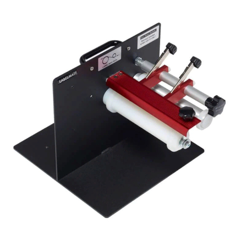
Intec SHINGLING CONVEYOR User manual

SHINGLING
CONVEYOR
Installation Guide - English

Intec Shingling Conveyor Installation Guide Intec Shingling Conveyor Installation Guide1 2
VERSION HISTORY:
MBH, JG: 19.05.14 V1
MBH, TW: 18.04.16 V2
© 2016 Intec Printing Solutions Limited. All rights reserved.
No part of this publication may be reproduced, photocopied, stored on a retrieval system or transmitted without the
express written consent of Intec Printing Solutions.
Intec Printing Solutions Limited
Unit 11B, Dawkins Road Industrial Estate
Hamworthy, Poole Dorset BH15 4JP UK
Tel: +44 (0) 1202 845960
Fax: +44 (0) 1202 845961
Web: www.intecprinters.com
Printed in the U.K.
Contents
Preface ..............................................................................................................................................3
About this manual..............................................................................................................................3
Before you start............................................................................................................................................ 3
Required tools.............................................................................................................................................. 3
Installation.........................................................................................................................................3
Unpacking the conveyor .............................................................................................................................. 4
Checking contents ....................................................................................................................................... 4
Assembling the conveyor legs ..................................................................................................................... 5
Attaching the output stacker tray to the conveyor....................................................................................... 7
Preparing your Intec printer and aligning the conveyor ............................................................................... 8
Connecting power...................................................................................................................................... 10
Input controls ............................................................................................................................................. 10

Intec Shingling Conveyor Installation Guide Intec Shingling Conveyor Installation Guide3 4
Preface
Every effort has been made to ensure that the information in this document is complete, accurate and up to date.
Intec assumes no responsibility for the results of errors beyond its control. Intec also cannot guarantee that changes
in software and equipment made by other manufacturers and referred to in this guide will not affect the applicability
of the information in it. Mention of software products, manufactured by other companies, does not necessarily
constitute endorsement by Intec.
While all reasonable efforts have been made to make this document as accurate and helpful as possible, we make no
warranty of any kind, expressed or implied, as to the accuracy or completeness of the information contained herein.
About this manual
This manual is intended for use by end users and Intec trained installation engineers. It explains how to install the
Intec shingling conveyor for your Intec printer.
Before you start
One (1) person may complete the setup of the Intec shingling conveyor.
Required tools
The following tools are required for installation (not supplied):
•Scissors or Utility Knife
•5mm Allen Key
•Phillips Head Screw Driver
Installation
Installation space
In addition to the physical size of the Intec printer, additional clearance space is required for the shingling conveyor.
1300mm
750mm
Unpacking the conveyor
Instructions for unpacking the shingling conveyor:
•Place the box on a flat surface or on the floor
•Using the scissors, cut the box banding and remove top cover
•Carefully remove all packaging materials from around the conveyor unit
•Lift conveyor from box, remove shrink wrap and verify the contents
•Report any missing items or shipping damage to Intec support: [email protected]
Checking contents
Ensure that you have all of the following items before beginning the installation:
1 - Conveyor
2 - Output stacker tray
3 - Cross bar
Boxed accessory kit
A - Black rectangular cap x 2
B - White round plastic cap x 4
C - Height adjustment screw (rear) x 2
D - Hardware Kit (detailed on page 5)
E - EU power cord
F - US power cord
G - Power supply
(UK power supplied where required)
2
1
3
BA C D
E F
G

Intec Shingling Conveyor Installation Guide Intec Shingling Conveyor Installation Guide5 6
X - Height adjustment screw and washer (front) x 2
Y - Cross bar screw and washer x 4
Z - Stacker tray screw x 3
Assembling the conveyor legs
Instructions for assembling the Intec conveyor legs before attaching to the Intec printer:
1. Remove the securing pin from the bottom of the front leg and remove the metal bar.
2. Rotate the front legs upward to re-insert the metal bar and locking pin at the new location.
X
Z
Y
3. Rotate the back legs upward to insert the metal cross bar. Secure each end of the cross bar by using 2 cross bar
screws (Y) with 2 washers.
4. Tighten the screws using a 5mm Allen Key (not provided).
Note: Ensure the screw is aligned with the corresponding hole on the metal securing bar.
Tip: Once the metal securing bar is rotated to the correct angle hold it in place with your forefinger and thumb
while turning the screw.
5. Insert white plastic caps (B) from the conveyor accessory kit into the holes in the frame.

Intec Shingling Conveyor Installation Guide Intec Shingling Conveyor Installation Guide7 8
Attaching the output stacker tray to the conveyor
Instructions for attachment of the stacker tray to the conveyor unit:
1. Place the shingling conveyor upright onto it’s legs. Remove the 2 small Phillips head screws from each side of
the conveyor unit. Retain screws and backing - these will be re-inserted once the stacker tray is manoeuvred
into place.
2. Remove the backing plate from each side and slide the stacker output tray into place
3. Align the screw holes in the conveyor with the stacker output tray, re-insert the backing plate and secure with
original screws. Secure stacker tray through the top of the conveyor using the three stacker tray screws (Z)
Preparing your Intec printer and aligning the conveyor
Instructions for preparing your Intec printer to receive the shingling conveyor:
1. Open the stacker face up exit tray of your Intec printer.
2. Locate the tray sensor tab to the rear of the tray, and with a knife remove the tab cleanly so there is nothing
protruding. This tab removal will allow your media to transport through the exit flap.
3. The exit flap is a closed and hinged flap which runs the width of the tray. Once located, lift the exit flap through
180 degrees and lock into position to open the exit slot. Close the stacker face up exit tray.

Intec Shingling Conveyor Installation Guide Intec Shingling Conveyor Installation Guide9 10
4. Roll the shingling conveyor into position. The conveyor table will not be at the correct height. Adjust height of front
legs by inserting height adjustment screw (X) into the top of front legs and turning in a clockwise rotation.
5. Raise the front of the conveyor until it’s edge is aligned with the top of the small rectangular groove as pictured
below (approx 20mm below exit slot).
6. Insert height adjustment screw (C) into rear feet as shown below and turn clockwise until conveyor table is level.
Insert black rectangular caps (A) into the top of the front legs.
Connecting power
Instructions for connecting power to the conveyor:
1. Locate power supply and power cord options in the accessory kit (provided). Select appropriate power cord
for your region and attach to the power supply and conveyor.
2. Plug the cable from the power supply into the back of the conveyor and power ON.
3. Conveyor will automatically advance to shingle media as it exits the printer. Increase/decrease speed of
belts as required.
Input controls
Instructions for the operation of the shingling conveyor:
SMALL RED LED Power is being supplied and the
Conveyor Belt is ON
I / O SWITCH [ I ] Power is ON
[ O ] Power is OFF
WHITE BUTTON Increases the belt speed for
more spacing between each
piece of media
BLACK BUTTON Decreases the belt speed for
less spacing between each
piece of media
RED BUTTON Starts or stops the Conveyor Belt
movement
LARGE RED LED The Conveyor is not ready to
feed (press the RED button to
begin feed)

Table of contents
Popular Printer Accessories manuals by other brands

Triumph Adler
Triumph Adler UTAX PF 780 Service manual
TROY Group
TROY Group Font Memory Card Kit installation guide
Toshiba
Toshiba GA-1040 Operator's manual
Ricoh
Ricoh 3800C Series installation guide

Canon
Canon Finisher-R1 General Timing Chart/General Circuit Diagram

Sawgrass Technologies
Sawgrass Technologies R1800 - Stylus Photo Color Inkjet Printer Getting started guide
