Intec CA10 User manual


2
ATTENTION
All text, photos, graphics, artwork and other material in the Instruction Manual
are copyrighted by Intec America Corporation and may not be published, broadcast,
rewritten or redistributed without permission.
Intec America Corporation, Inc. (Intec) text, photo, graphic, audio and/or video
material shall not be published, broadcast, rewritten for broadcast or publication or
redistributed directly or indirectly in any medium. Neither these Intec materials nor any
portion thereof may be stored in a computer except for personal and non-commercial use.
Any unauthorized use of this material by anyone other than the original owner of the
Intec-America Copper Ionic Technology shall be prosecuted under applicable Federal
Laws.
© 2022 Intec America Corporation

3
Table of Contents
1. VALUE OF COPPER IONIZATION SYSTEMS................................................4
2. CA10 AND CV50 INSTALLATION OVERVIEW.............................................6
3. CV60 INSTALLATION AND OVERVIEW.....................................................11
4. START-UP PROCEDURE FOR YOUR POOL ................................................20
5. SWIMMING POOL / SPA MAINTENANCE...................................................21
6. WATER CHEMISTRY –TESTING YOUR POOL WATER...........................21
7. CLARITY OF YOUR POOL WATER ..............................................................25
8. TIPS TO PERFECTION.....................................................................................27
9. STAINS AND SCALE........................................................................................28
10. ATTER THE STORM AND TREATMENT......................................................28
11. ELECTRODE MAINTENANCE –REPLACING BARS .................................29
12. CHARTS.............................................................................................................30
13. WARRANTY AGREEMENT............................................................................34

4
1. VALUE OF COPPER IONIZATION SYSTEMS
You have purchased a chemical-free water treatment system that eliminates the need for
chlorine. A system that is state of the art. We are committed to make servicing your pool
and swimming more pleasurable, less time consuming, and more economical to maintain.
As a bonus, you’ll find a chlorine-free pool healthier for you, your family, and friends.
Before installing the Ionizer, read these instructions from cover to cover. Write down any
questions you have. If, after reading the entire booklet, you still have questions; PLEASE
CALL US –TOLL FREE. You will be glad you did.
The following is a partial list of the health benefits copper mentioned in the article in the
February 1989 issue of Better Nutrition Magazine written by contributing Editor Frank
Murry.
1. Copper strengthens blood vessel walls.
2. Copper is important to energize metabolism.
3. Copper shares anti-inflammatory powers with zinc, which is important in healing.
4. Taste perception may be influenced by copper.
5. Copper is important to the functionality of the immune system
6. Copper is a potent anti-ulcer agent.
7. Copper also may play an important role in cancer prevention.
8. Copper is one of the more important antioxidants in the blood stream.
9. Copper is the key mineral of collagen and elastin which are essential for tendons
and blood vessels.
10. Copper helps prevent anemia, bone and skeletal defects, a degeneration of the
nervous system, defects in the color and structure of hair, reproductive problems
and abnormal cardiovascular problems.
11. Those who are deficient in copper and iron are more likely to have problems with
sleeping.
12. Nerves will fray without copper.
13. Without copper, skin becomes fragile, will break easily, and heal slowly.
14. Without copper, bones can fracture
15. Without copper, blood vessels can leak or burst.
16. Copper deficiency can elevate blood pressure.
17. A copper-deficient diet may cause defective transport of vitamin A from liver to
blood.

5
Copper, while extremely important in one’s diet, should not be confused with swimming
pools or consuming bathing water. Copper ionized pools do have its own benefits whicg
are outlined below:
1. Copper Ionization is the only way to have healthy water in your pool.
2. You will save 80-85% on your water care expenditures and 80-85% on your
water care time. There is no need for purchasing chlorine, shock treatments,
algaecides, or stabilizer!
3. Pool liners, paint, vinyl, and plaster last three to five times longer, saving
thousands of dollars.
4. Copper ions are non-irritating to skin and will not burn your eyes.
5. Copper ions are many times more effective, faster acting, and longer lasting
than chlorine in inactivating algae and bacteria.
6
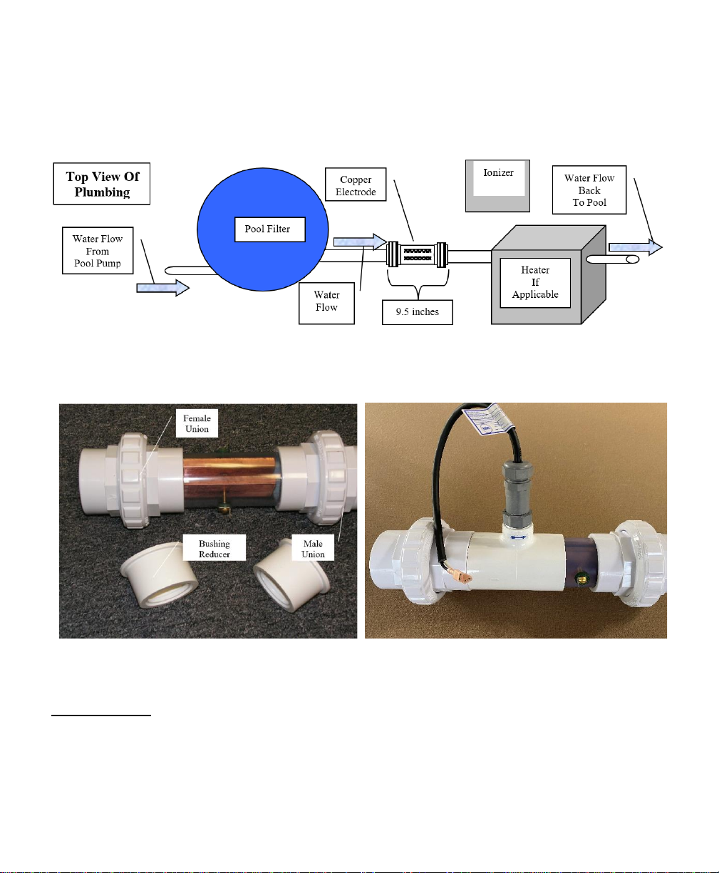
2. CA10 AND CV50 INSTALLATION OVERVIEW
The copper electrode is the only part of the system that must be installed. It is installed
after the pool filter and before the pool heater (if you have a heater).
Figure 1
Figure 2. CA10 and CV50 Electrode
Figure 3. CV60 Electrode
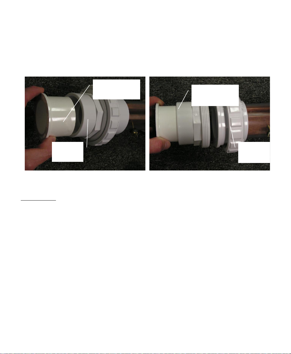
Installation of the Electrode
1.5” Plumbing
You will need to use a 2” to 1.5” reducer bushing (not provided). The electrode
can be installed horizontally or vertically. Take the male half of each male union, clean
them both, and then cement the bushing/reducer into the male union (Figure 4).
7
Use a hacksaw and cut approximately 10 inches out of the pipe after the filter
Please note –this measurement can be different as bushings vary in depth. Take the male
half of each union that contains the reducer/bushing, clean the inside and cement
assembly component on the remaining pipe ends (Figure 5). Slide in the electrode and
hand tighten the female union to the male union.
Figure 4
Figure 5
2” Plumbing
Use a hacksaw and cut approximately 9.5 inches out of the pipe after the filter
The electrode can be installed horizontally or vertically. Take the male half of each union
and clean and cement them on the remaining pipe ends. Slide in the electrode and hand
tighten the female union to the male union.
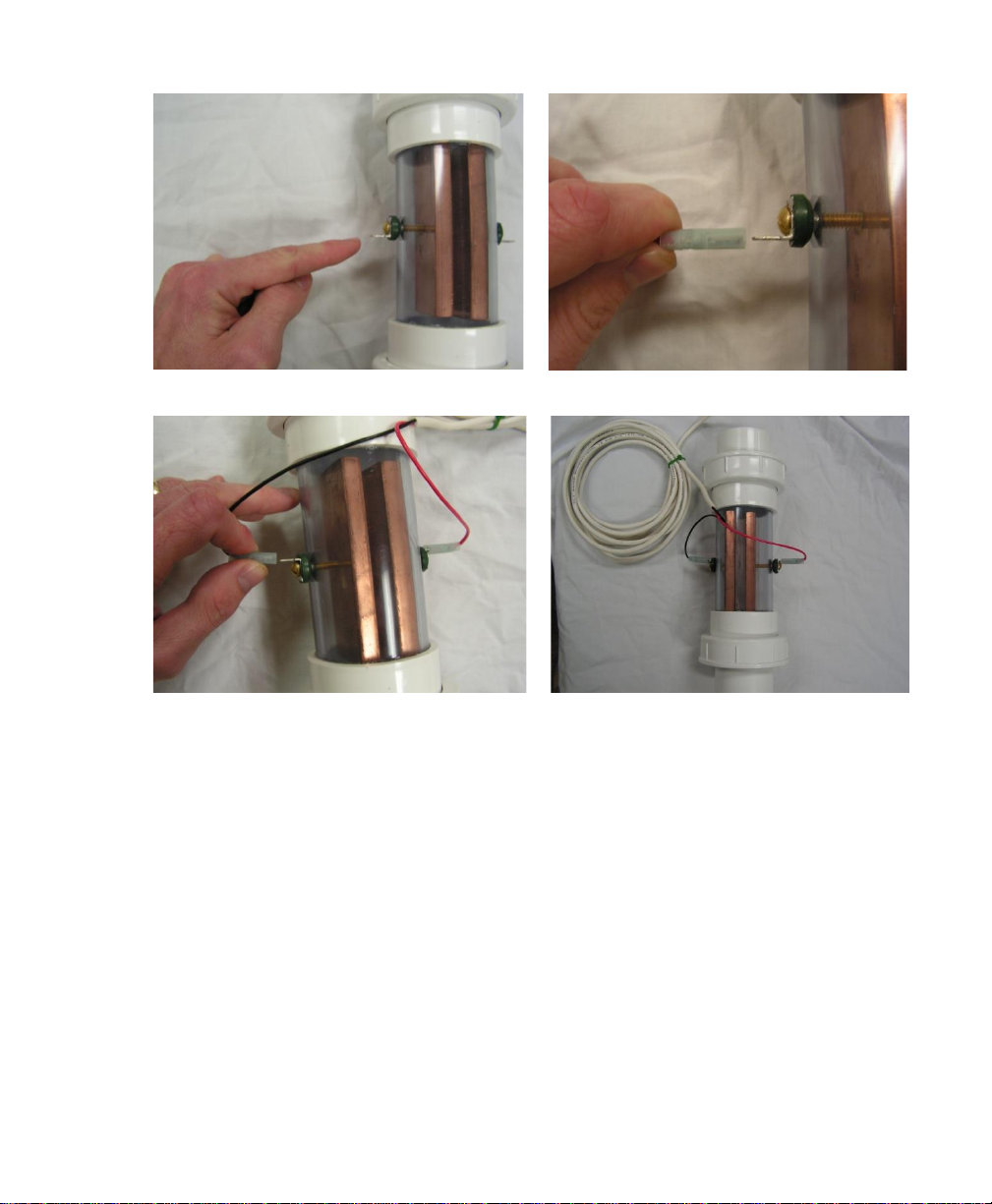
Connecting the Electronics Unit to the Electrode
Locate the male spades found at each side of the electrode (Figure 6). Connect the
female plug located at the end of the wire from the electronics unit and connect it to the
male spade located on the electrode (Figure 7). Attach the unconnected wire for the
electronics unit to the other side of the electrode (Figure 8). It does not matter which wire
plugs into which side of the electrode. The polarity will alternate the current between the
two copper bars on the electrode. Figure 9 illustrates the proper connection for the
electronics unit to the electrode.
Bushing
Reducer
Assembly
Component
Female
Union
Male
Union
8
Figure 6
Figure 7
Figure 8
Figure 9
Your new pool ionization system has gone through two separate inspections: (a) by
manufacturing, and then, (b) by the shipping department. If you notice any defects on your
system, please contact our Quality Assurance Department immediately.
Your unit utilizes an international power supply 110-230 volts, has a Type B plug,
and can be plugged into any standard US electrical socket. Many modern pool system
controllers have auxiliary plugs/ports that can be programmed to the ionizer turn on and
off. Copper ions remain active for a long period of time, and you should not have to run
the system continuously. These control units may also be plugged into a timer (available
at hardware stores) for maintaining a copper residual. The use of an extension cord will not
affect this system.

9
If the unit will be connected to an automated controller, please refer to the
instruction manual of that unit. Your ionizer can be connected to an auxiliary port. Many
of the modern control panels connect via blue tooth with a smart phone offering remote
access and the ability to manipulate run-time programs.
Electronic Controller Specifications
CA10
CV50
Input Voltage US
120/220
120/220
Input Voltage - Europe & Asia
230
230
Hertz (US/Europe & Asia)
60/50
60/50
Volts DC
12
24
Amps
2
1
Maximum Watts
24
24
The electronic controllers must be mounted upright on a wall and preferably at a
location underneath the eve of the roof. At no time, should the controller be left laying
on a surface facing upwards. By doing so, the controller could be inundated with
water and void warranties.
*The total dissolved solids (TDS related to salinity) level in the pool will affect the
rate and dosing of the cupric copper production. The same can affect the internal
heating at full load and result in an automated shutdown. The output current should
be reduced when this occurs.
NOTE –Only run the
CA10 & CV50
controller when the
pump is ON

10
CA10 and CV50 Overview
Item #
Description
1
2
3
4
5
Power Indicator Light. It will remain a solid red color when power is running
to the unit.
Polarity Light –Cycles on and off every 10 minutes, indicating a reversal of
polarity and cleaning cycle.
Potentiometer Switch –Rotate clockwise to increase copper output and
counter clockwise to decrease copper output.
Power Switch –Will allow the user to turn off the system when it is not in
use.
Electrode Leads –Attaches to the copper electrode (not shown in picture)
11
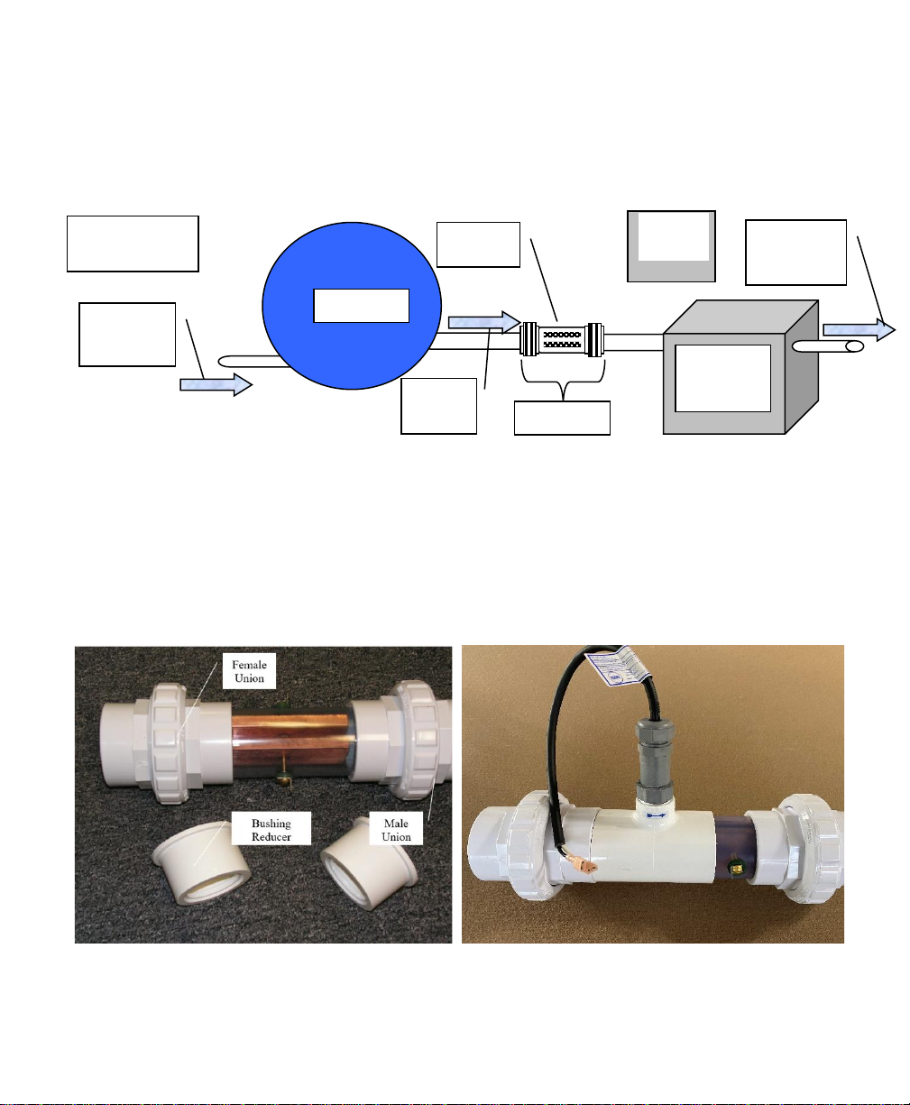
3. CV60 INSTALLATION AND OVERVIEW
The copper electrode is the only part of the system that must be installed. It is installed
after the pool filter and before the pool heater (if you have a heater).
Figure 1
Your new CV60 pool system contains an integrated flow switch (Figure 3) that is
not available with the CA10 or CV50 (Figure 2). The electronics controller should have
continuous power supplied even if the pool equipment is off
. The system will be on
standby even when the display is illuminated. The CV60 will only produce copper
when the pool pump is running, and water is flowing through the electrode activating
the flow switch.
Figure 2
Figure 3
Ionizer
Water
Flow
Top View Of
Plumbing
Copper
Electrode
Water Flow
From
Pool Pump
Pool Filter
9.5 inches
Heater
If
Applicable
Water Flow
Back
To Pool

12
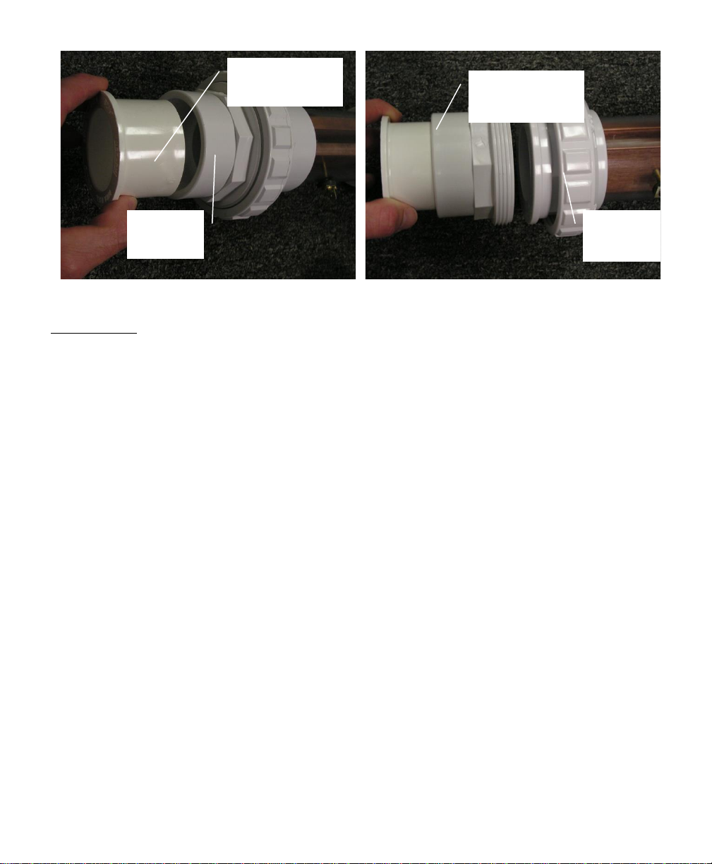
Please note the arrow shown in Figure 4 below. The water flows from the pump,
through the filter,
into the electrode or flow cell. Ensure the water leaving the cell
flows in the direction of the arrow or your system will not produce copper. Figure 5
shows the entire electrode with the lead wires from the flow switch that will connect
to your CV60 electronics system.
Figure 4
Figure 5
Installation of the Electrode
1.5” Plumbing
You will need to use a 2” to 1.5” reducer bushing (not provided). The electrode
can be installed horizontally or vertically. Take the male half of each male union, clean
them both, and then cement the bushing/reducer into the male union on the electrode
(Figure 6).
Use a hacksaw and cut approximately 12 inches out of the pipe after the filter.
Please note –this measurement can be different as bushings vary in depth. Take the male
half of each union that contains the reducer/bushing, clean the inside and cement assembly
component on the remaining pipe ends (Figure 7). Slide in the electrode and hand tighten
the female union to the male union.
13
Figure 6
Figure 7
2” Plumbing
Use a hacksaw and cut approximately 11.5 inches out of the pipe after the filter
The electrode can be installed horizontally or vertically. Take the male half of each union
and clean and cement them on the remaining pipe ends. Slide in the electrode and hand
tighten the female union to the male union.
Connecting the Electronic Controller to the Flow Switch
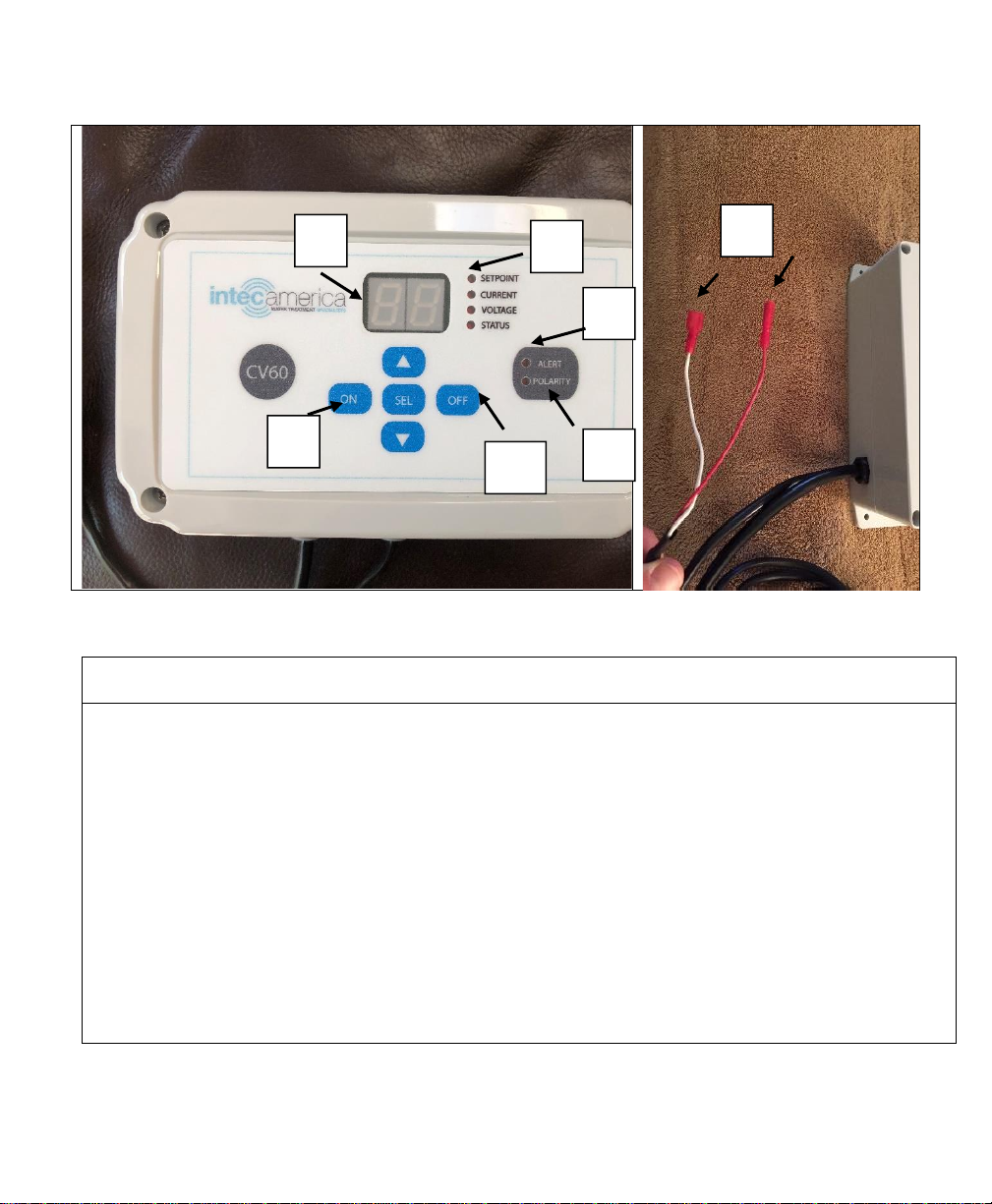
There are 4 wire connections coming from the CV60 terminal. Please note, the
red female plugs of the electronics system will plug into the red male plugs of the flow
switch as shown below (Figure 6).
Connecting the Electronic Controller to the Copper Electrode
Locate the male spades found at each side of the electrode (Figure 7). Connect
the blue female plug from the CV60 electronics unit to the male spade located on the
side of the electrode (Figure 7). Attach the unconnected wire for the electronics unit
to the other side of the electrode (Figure 5).
It does not matter which wire plugsinto
which side of the electrode.
The polarity will alternate the current between the two
copper bars on the electrode. Figure 8 illustrates the proper connection for the
electronics unit to the electrode.
Bushing
Reducer
Assembly
Component
Female
Union
Male
Union

14
Figure 6
Figure 7
Figure 8
Your new pool ionization system has gone through two separate inspections: (a) by
manufacturing, and then, (b) by the shipping department. If you notice any defects on your
system, please contact our Quality Assurance Department immediately.

15
Your unit utilizes an international power supply 110-230 volts, has a Type B plug,
and can be plugged into any standard US electrical socket. Many modern pool system
controllers have auxiliary plugs/ports that can be programmed to the ionizer turn on and
off. Copper ions remain active for a long period of time, and you should not have to run
the system continuously. These control units may also be plugged into a timer (available
at hardware stores) for maintaining a copper residual. The use of an extension cord will not
affect this system.
If the unit will be connected to an automated controller, please refer to the
instruction manual of that unit. Your ionizer can be connected to an auxiliary port. Many
of the modern control panels connect via blue tooth with a smart phone offering remote
access and the ability to manipulate run-time programs.
CV60
*The total dissolved solids (TDS
related to salinity) level in the pool
will affect the rate and dosing of the
cupric copper production. The same
can affect the internal heating at full
load and result in an automated
shutdown. The output current should
be reduced when this occurs.
Input Voltage US
120/220
Input Voltage - Europe &
Asia
230
Hertz (US/Europe & Asia)
60/50
Volts DC
24
Amps
2
Maximum Watts
48
The electronic controllers must be mounted upright on a wall and preferably at
a location underneath the eve of the roof. At no time, should the controller be left
laying on a surface facing upwards. By doing so, the controller could be inundated
with water and void warranties.
The CV60 Electronic Unit
is Always Powered On. Copper
is Produced Only When the
Pump Recirculates the Water.
16
CV60 Overview
Item
#
Description
1
2
3
4
5
6
7
LED Display
Power ON Switch
Power OFF Switch
Control Status Indicators
Alert Indicator –Alarm codes change depending on application (listed below)
Polarity Light –Cycles on and off every 10 minutes, indicating a reversal of polarity
and cleaning cycle.
Attaches to the copper electrode (not shown in picture)
7
2
3
4
1
5
6

17
CV60 Operator Interface
Display
The CV60 has a two digit seven-segment LED display. The segments are driven direct so
a limited set of alpha characters can be displayed in addition to numbers.
The following is a list of displayed variables on the CV60:
1. Setpoint Amps –00 to 20
2. Cell Amps –0.0 to 2.0 (accuracy of +- 0.1 amps)
3. Cell Volts –1 to 24
4. Control Status & Alerts
a. A0 –Normal operation
b. E1 –Flow switch open (no water flow)
c. E2 –Cell connection problem or low TDS indication (cell is powered with
no feedback). See notes page 19
d. E3 –Output reduced because of internal heating. Too high TDS in water,
too high of a setpoint, or combination of both.
5. Power-up Mode
a. P1 –Powers up off
b. P2 –Powers up on (default as shipped)
The display variables can be changed by pressing the “SEL”pushbutton and indicated by
the LED Light to the left. Options are SETPOINT, CURRENT, VOLTAGE. The
SETPOINT is the default and one can increase/decrease the rate of copper production by
simply pressing the “UP” or “DOWN arrows to increase or decrease the copper ion
output while the LED is next to the SETPOINT indicator.
Current and Voltage
One can also change the power output by pressing the “SEL” pushbutton until the LED
indicator is located next to the SETPOINT. Use the “UP” or “DOWN arrows to change
the copper output. To view the output, press the “SEL” pushbutton until the indicator is
next to CURRENT (amperage) or VOLTAGE (direct current volts). The CURRENT is a
better indicator of the rate copper will ionize. It is best to keep this under 1.7 to prevent
overheating or accelerated copper depletion. The combination of these two items is more

18
useful to a technician for troubleshooting and it is suggested to just use the setpoint
screen.
Manual Power On/Off or Automatic One
The CV60 is shipped standard where one must manually turn the system on. This is best
utilized when the system is plugged into a standard outlet, wired into a timer, or utilizing
the flow switch. To power up, simply press the “ON” button. To turn the system off,
simply press the “OFF” button. If being used with a flow switch or the system is wired
into the pump or timer, then you want power applied to it whenever the pump is running
which is the default Program P2. For those that only want to run the system when
needed and manually control the addition of copper (usually one a week), one needs to
change the program to Program P1.
Changing the Power-up Mode
To change this setting the system must be plugged in and manually press the “OFF”
button. With the unit now powered off, unplug the CV60 from the incoming power
supply. Press and hold the “DOWN ARROW” while plugging the power cord back into
the power outlet. A “P1 or P2 code will be displayed. Please see above for the selection
preference. Push the “SEL” push button to lock this program in and return to the home
screen.
The Power-up Mode will be displayed when the DOWN ARROW panel
pushbutton is pressed and held down when AC power is being applied.
Setpoint Select
The copper ion release rate on the CV60 is adjusted using scroll up and scroll down panel
pushbuttons when the LED indicator is next the “Setpoint”. The controller will maintain
the last used setpoint value during power down or when power is reapplied to the system.
Power On & Off
Power on and off on the CV60 may be selected via ON and OFF panel pushbuttons.
rather than a power toggle switch found on the CA10 and CV50.
Alert LED
The ALERT LED will illuminate if any of the E1 to E3 conditions described earlier are
present.

19
E2 –The most probable cause for this error is having extremely low mineral
content in the pool water. The average Total Dissolved Solids (TDS) level for a
freshwater pool is 500 - 1500 ppm and salt water pools 2800 –3500 ppm. This
error code will show on the display when the TDS is lower than 250 ppm. The
system is functioning properly. However, it will take a very long time to increase
copper levels in your pool. To increase the TDS, add a 40-pound bag of
swimming pool salt for a 20,000 gallon pool to increase the TDS level
approximately 250 ppm. See Table 4 in the back of this manual for calculations.
Polarity LED
The polarity changes after 10 minutes or when AC power is applied, but not via the ON
and OFF buttons. This is a self-cleaning cycle to keep the cathode and anode clean and
reduce the potential of mineral scale plating.

20
4. START-UP PROCEDURE FOR YOUR POOL
Start-up of Pool
This order of instructions should be followed precisely to properly ionize your pool. If you
are converting from chlorine, salt water generated, or other sanitation method, there is no
need to drain your pool.
1. Clean out all debris and clean out skimmers (Please see Section 9.0 if applicable)
2. Adjust pH between 7.0 –7.4
3. Run the Ionizer continuously until the copper level reaches 0.5 ppm.
REMEMBER: Your pool pump must be running and water must be flowing
over the copper bars when the Ionizer is on.
4. Treat water clarity
5. Treat Calcium Hardness
Initial Start-up for the CA10 or CV50
These unit are equipped with a potentiometer to control the copper output. Turn the
dial counterclockwise to the lowest setting, and turn the unit on with water flowing through
the copper electrode chamber. As the water is flowing through, turn the dial clockwise
until it is on full power. If the power light flashes/blinks sporadically, turn the knob
again counterclockwise until the power light is solid and not flashing. This is the
maximum output for your pool water conductivity.
Initial Start-up for the CV60
Similar to the above. However, this unit is equipped with push buttons to control the
copper output. Turn the unit on with water flowing through the copper electrode chamber.
As the water is flowing through, pay attention to the LED lights to the right of the display.
If the any light flashes/blinks sporadically, push the down arrow one click at a time
until the power light is solid and not flashing. This is the maximum output for your pool
water conductivity.
Other manuals for CA10
1
This manual suits for next models
2
Table of contents
Other Intec Swimming Pool manuals


