Intech Micro 2400-A16-SD-NET User manual
Intech Micro
2400-A16-SD-NET
Supplementary Manual to the
2400-A16 Installation Guide.

2
2400-A16-SD-NET Supplementary Manual Index.
Description. Page 3
Features. Page 3
Quick Overview of using the 2400-A16-SD-NET Logger. Page 3
Ordering Information. Page 4
Ordering Examples. Page 4
Other 2400 Models. Page 4
2400-A16-SD-NET Terminals and Layout & Dimensions. Page 5
Section 1 - 2400-A16-SD-NET Station. Page 6
Section 2 - Intech Micro Station Programmer Software. Page 7
Station Setup - Setting up the 2400-A16-SD-NET for Logging. Page 8
SD Card Configuration and Setup. Page 9
Memory Viewer Mode. Page 9
Configuring Page & Line Settings to Extract Data to. Page 9
Initialise SD Card. Page 10
Importing SD Card Data into Station Programmer. Page 11
Identify SD. Page 12
Viewing the SD Graph. Page 12
Exporting Data From Station Programmer. Page 14
Importing SD Card Data into Station Programmer via Comms. Page 15
Manual Comms Download. Page 15
Automatic Comms Download. Page 16
Product Liability. This information describes our products. It does not constitute guaranteed properties and is not intended to affirm the suitability of a
product for a particular application. Due to on-going research and development, designs, specifications, and documentation are subject to change
without notification. Regrettably, omissions and exceptions cannot be completely ruled out. No liability will be accepted for errors, omissions or
amendments to this specification. Technical data are always specified by their average values and are based on Standard Calibration Units at 25C,
unless otherwise specified. Each product is subject to the ‘Conditions of Sale’.
Warning: These products are not designed for use in, and should not be used for patient connected applications. In any critical installation
an independent fail-safe back-up system must always be implemented.
Important: This Supplementary Manual is to be read in conjunction with the 2400-A16 Installation Guide.
3
Intech Micro
2400-A16-SD-NET
Features.
Logging of Analogue Inputs 1~16, Digital Inputs 1~4 and Ambient Sensor onto an SD Card.
Up to 7858811 Data Samples.
Data Store Rates Selectable From 1sec ~ 60min.
Cyclic or Stop Modes when SD Card is Full.
Internal Real Time Clock with Battery Backup.
Read SD Memory Card by removing SD Card and Reading from a Computer SD Port, or using Comms.
16 Isolated Universal Analogue Inputs, with Plug In Terminals.
Each Input Individually Selected & Scaled.
Four Dedicated Digital, Isolated, Optocoupler Inputs.
Two Analogue, Isolated, 4~20mA Outputs.
Two Digital, Isolated, Relay Outputs.
Comms Ports (also note the protocol information listed below):
Port 1: Isolated Ethernet TCP/IP.
Port 2: Isolated RS232/RS485.
Port 3: USB programming port via XU-USB programming key.
Embedded protocols, Auto Detecting:
MicroScan ASCII.
Modbus RTU.
Modbus TCP.
Easy Programming and Memory Viewing etc using Intech Micro Station Programmer software.
Universal AC/DC Power Supply (three options to select from):
H = 85~265Vac, 95~370Vdc. (Standard)
M = 24~48Vac, 17~72Vdc.
L = 10~30Vdc.
Compact 35mm DIN Rail Mounting.
Easy to Install.
Low Cost.
SD Memory Logging.
16 Universal Analogue Inputs.
4 Dedicated Digital Inputs.
2 Analogue 4~20mA Outputs.
2 Relay Outputs.
Description.
The SD version of the 2400-A16 is a great way to achieve a stand-alone
method for data logging. The station can be used as a 16 input stand-alone
logger, or as part of a SCADA data high way with backup logging facility.
The user friendly, free to download Intech Micro Station Programmer
software (version 5.2.3613.5 or later), supports the reading of SD cards on
the 2400-A16-SD-NET.
Quick Overview of using the 2400-A16-SD-NET Logger.
1. Station Setup:
Configure the 2400-A16-SD-NET station with Input types as required.
Configure the 2400-A16-SD-NET station’s SD recording parameters.
2. SD Card Setup:
Configure the Pages & Lines for all Inputs being used.
Initialise SD card if more than one computer is used for download.
3. Record:
Insert the SD card into the 2400-16-SD-NET’s SD slot, you will hear the latch on the SD socket ‘click’.
The RECORD LED will flash while the log file is created. Once logging has started, the RECORD LED will stay on.
If the log file is already there, the 2400-A16-SD-NET will use that and the RECORD LED will come on straight away.
4. Download:
Using either an SD port on the computer or the 2400-A16-SD-NET’s Comms, all new data is downloaded into the
Station Programmer software and stored in a log file.
4
XU-USB
USB Programming Key for programming 2400-A16-SD-NET using Station Programmer software.
(Same Key as used for programming XU Series transmitters, Z-2400-Sleeper, Z-2400-A2 Series, IN-uP4 and uP4-Din).
Note: The 2400-A16-SD-NET can also be programmed via the on-board Comms Ports.
Ethernet: The XPort® Ethernet converter must be programmed via the Ethernet TCP/IP port.
Ordering Examples.
2400-A16-I16-SD-NET-H: 2400-A16 with 16 Isolated Universal Input Channels, SD Card Logging,
Ethernet TCP/IP Comms, 85~265Vac, 95~370Vdc Power Supply.
2400-A16-I16-SD-NET-L: 2400-A16 with 16 Isolated Universal Input Channels, SD Card Logging,
Ethernet TCP/IP Comms, 10~30Vdc Power Supply.
ITEM CODE DESCRIPTION
SERIES 2400-A16-I16-SD-NET- 16 Isolated Universal Input Channels. SD Data Logging.
Port 1 Fitted with Ethernet TCP/IP Comms.
Power Supply Options H 85~265Vac, 95~370Vdc. (Standard)
M 24~48Vac, 17~72Vdc.
L 10~30Vdc.
Other 2400 Models Include:
2400-IS: Isolated Auto-Detecting USB/RS232 to RS485/422/232 Converter.
2400-R2: 16 Channel Relay Output Expander for 2400-A16.
Z-2400-RB: Wireless Base/Remote for RS485/422/232 Comms.
Z-2400-TCP: Wireless Base only for Ethernet TCP/IP Comms.
Z-2400-Sleeper: Wireless Battery Option for 2 Universal Inputs.
Ordering Information.
All 2400-A16 stations come standard (Default ex factory calibration) with:
All Input Channels Configured to RTD Pt100 0~100°C.
4 Dedicated Digital Inputs.
2 Analogue 4~20mA Outputs.
2 Relay Outputs.
RS485 or RS232 on Comms Port 2.
Note: XPort® is a Registered trademark of Lantronix, Inc.

5
2400-A16-SD-NET Terminals and Layout & Dimensions.
255mm
145mm
60mm
SD Card Slot.
USB Programming Port
(Use with XU-USB
USB Programming Key).

6
Section 1 - 2400-A16-SD-NET Station.
PLEASE READ THE FOLLOWING CAREFULLY.
Intech Micro Station Programmer Software.
This user friendly, free to download software supports the reading of SD cards on the 2400-A16-SD-NET.
SAFE EJECT.
When the SD card is to be removed from the station, the ‘PRESS BEFORE REMOVING SDPRESS BEFORE REMOVING SDPRESS BEFORE REMOVING SD’ Safe Eject
button must be pressed first. This allows the station software to close the logging file and write key
information to the file.
Important: If you forget to press the Safe Eject button, DO NOT put the SD card back into the 2400-A16-SD-NET
station as the stored data will be overwritten. Take the SD card and insert into a computer with the Station Programmer
software, as this should be able to repair the card’s data.
SD Cards.
Please only use the supplied micro SD cards from Intech Instruments Ltd.
Always handle the SD cards carefully - avoid touching the gold contacts.
The SD software stores the 2400-A16-SD-NET station’s serial number in the SD card. When the same SD card is put
back into the same station, the serial number will be recognised and data will be added to the end of the existing data
series. When the SD card is full it will be rolled over (default). If the SD card is inserted into a different station, the soft-
ware will start storing data at the start of the SD data file, overwriting any old data from the previous station.
When the SD card is out of the station, no data is stored in the station.
The SD card stores data records only, not any of the 2400-A16-SD-NET station’s configurations.
Memory Details & Store Rates.
1GB = 7858811 samples.
Store rates are selectable from:
1, 2, 5, 10, 15, 20 or 30 seconds,
1, 2, 5, 10, 15, 20 or 30 Minutes,
or 1 Hour max.
Data is stored on the minute for minute rates.
Second rates are stored on the second. (i.e. 5 sec will be 0, 5, 10, 15... seconds. 15 seconds will be 0, 15, 30... seconds.)
Data is NOT averaged during the storage interval, so the stored reading is the value at the time that the sample is taken.
Station Real Time Clock.
The Station time is set by the station programming dialog box. It is set to UTC time and data records are stored using
UTC time. This means that when the data is read out it is converted to the Local Time by the Windows time settings on
the local computer and thus will be automatically converted according to daylight/standard time zones. Battery life for the
real time clock is 5 years typical.
Station SD LEDs.
STATUSSTATUSSTATUS Flashing The SD logger is operating normally.
ON SD card error or flat battery fault. Use software to
determine fault.
RECORDRECORDRECORD ON The SD card is recording data.
OFF The SD card is not recording.
Flashing The SD card is being formatted (creating SD logfile).
SAFESAFESAFE ON The SD card is safe to eject.
OFF The SD card is not safe to eject.
Normal 2400-A16 Station functions.
When the SD mode is being used all other 2400-A16 station functions will operate normally. For example: comms on
PORT 1/2, PLC RTX modes, etc.
Reading SD data via Serial.
When using the Serial mode to read SD data, ONLY ONE COMPUTER CAN READ DATA FROM THE SD CARD.
I.e. It is NOT possible to use the memory software on Port 1 and then connect another computer on Port 2 to read the
same SD data from the same station.

7
Section 2 - Intech Micro Station Programmer Software.
The user friendly Intech Micro Station Programmer Software is used for programming the Intech Micro 2400/2100
stations and the reading of SD cards on the 2400-A16-SD-NET.
This software can be downloaded for free from www.intech.co.nz/downloads
Install the software.
Use the desktop icon ‘Intech Micro Station Programmer’ to start the software.
Software Overview:
Note: Stations with SD software fitted will be shown with SD in the list of previous stations programmed.
Tab: Description / Use:
Serial Connection - COM/USB Adding Intech Micro stations via Serial connection.
Network Connection - Ethernet Adding Intech Micro stations via Ethernet TCP/IP network - NET stations.
Memory View SD Read Read SD cards via Computer SD port & View Graphs.
Memory View Comms Read SD memory via comms/Ethernet. Manual and Automatic uploads.

8
Station Setup - Setting up the 2400-A16-SD-NET for Logging.
Add the station to the Station programmer: click
Note: You must add the station to the memory of the software so the station Input Ranges and Memory Pages & Lines
setup can be completed.
If an SD card is not fitted to the station the following will be displayed (when the station programming info is read out):
Storage Mode.
Default setting is to ‘Cyclic Memory’, which is set to
overwrite the oldest samples when the SD Card is full.
Recording Rate.
Select the Record Rate from the drop down menu.
(e.g. Scan all channels every 5 seconds.)
Duration Details are calculated automatically based on
the chosen Record Rate.
Station Clock.
To program current computer time to the station, tick the
‘Set Clock On Station Program’ box.
To finish click ‘OK’, then click ‘Program’ to save the
settings to the 2400-A16-SD-NET station.
NOTES:
The record rate should be chosen to suit the rate required. The rate selected also determines how existing store
data is displayed in the same manner as store data is read from MicroScan data files in MicroScan.
Changing the recording rate is not recommended, the pages and lines screen displays data at the current record
rate. Therefore any data before the change will be displayed at incorrect frequencies.
‘Clear Station Memory’ and ‘Set ReadPtr = WritePtr’ are both engineering test settings.
Diagnostics: For normal operation, the ‘Number of Samples’ will be 7858811, ‘Write Pointer’ will be a non zero
value and SD status = ‘81 OK’.
In this area you can setup the station’s input/output type
and configurations. Further information can be found in
the 2400-A16 Installation Guide.
A 2400-A16 with SD software will be shown in the lower
info panel: A16 SW Ver = 6.15,0.05. 0.05 = SD version.
The SD Recording button will also be shown. Click this
to load the ‘SD Recording’ window.
Station Programmer SD Recording Options.

9
Memory Viewer Mode.
In the Memory Viewer mode, the Connection tabs are removed and the software can only be used for SD memory
functions.
Click the button.
To return to Full mode, click the button.
Configuring Page & Line Settings to Extract Data to.
NOTE: These settings are stored on the LOCAL COMPUTER.
If the data is to be read out on another computer, you must use the ‘Initialise SD Card’ step (see page 10), to
copy the settings to the SD card(s) used with this station.
Add the station to the Station Programmer as above.
SD Card Configuration and Setup.
Click ‘Configure Pages & Lines’.

10
Select the station,
then click the ‘Configure Pages & Lines’ button.
To edit a page, select the page and click ‘Edit Page’.
To edit a line, select the line and click ‘Edit Line’.
To create a new page, click ‘Add Page’.
Up to 10 pages can be created, with up to 10 lines
per page.
Initialise SD Card.
The Initialise SD Card step is used to copy station programming and setup info to the SD card. This means that the
same card can be read using another computer. This step needs to completed with the SD card in the computers SD
card slot.
On the ‘Memory View SD Read’ tab or in the ‘Configure Pages & Lines’ screen, click the ‘Initialise SD Cards’ button.
Insert the SD card that is to be used with this station into
your computers SD card slot.
Select the relevant station from the Station List.
Then click ‘Copy Setup Files to SD Card’.
NOTE: The Initialise SD step copies setup data to the SD
card in separate files from the main log file. It is not related
in any way, apart from being a tool to extract data out from
the log file.
In addition to copying the files, ‘CARD_A’, ‘CARD_B’ etc.
will be written to the cards volume name in an aid to
identify the card when viewed with Windows Explorer:

11
Importing SD Card Data into Station Programmer.
Press the Safe Eject button on the station (‘PRESS BEFORE REMOVING SDPRESS BEFORE REMOVING SDPRESS BEFORE REMOVING SD’ button ).
The SAFE LED will come on. Press the SD card in, this will unlock the SD latch and the card will pop out slightly. The
SAFE LED will go out. Remove the SD card and place into a SD reading tool (either SD adaptor or USB to SD adaptor),
then plug into the computer. Windows should detect the SD card as a removable drive.
On the SD software, click the ‘Memory View SD Read’ tab. Click the ‘Import SD Data’ button. The SD software will
search the computers removable drives for the SD log file and then read the data out. All new downloads are read to
new files and then mapped together for graphing.
When the SD read is complete, the SD card needs to be returned to the station as soon as possible for logging to
resume. Safely Eject (see below), the SD card from the computer and take it to the 2400-A16-SD-NET. Insert the SD
card and you will hear a click, the RECORD LED should come back on.
After the Safe Eject button is pressed, you have 20 seconds to remove the SD card. After this time the Safe LED will go
out and RECORD mode starts again.
Click ‘Import SD Data’.
Click ‘OK’
Completion information is shown.
The View Graph window will then be displayed.
Please take the SD card out of the computer (Use Windows safely remove hardware) and insert back into the
2400-A16-SD-NET.
Each SD upload is read into one set of files in the memory viewer program, and chained together using the MicroScan
History page.map files.
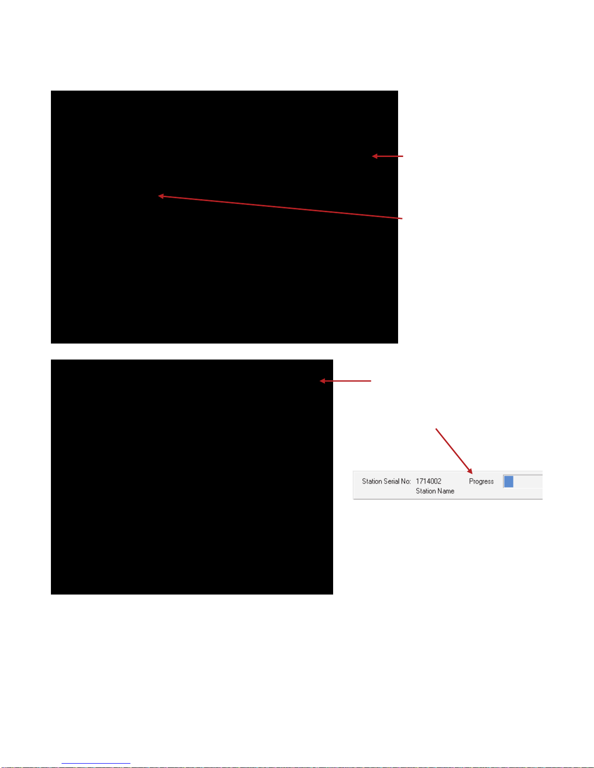
Progress windows as data is being read:

12
Viewing the SD Graph.
Use the ‘View Graph’ button from the ‘Memory View SD Read’ tab to view the history
data. This opens a MicroScan history viewing window that allows display of the history
data in history mode and batch mode.
To select the station/page to be viewed, choose from ‘Viewing’. The most recent station
that has been read will be highlighted in grey.
History View of data.
Click ‘View Data’ to view the time/date stamp of all data in the SD file
as shown below.
Identify SD.
The Identify SD function will allow you to show what information is on the card without extracting it:
Insert the SD card into the computer and click the ‘Identify SD’ button.

13
Batch View of Data.
The Batch view shows each download as one screen of data.
Display Options can be used to change background colour and fonts.
Line Details
Graph Scale
Mouse Track
Multi Track

14
Exporting Data From Station Programmer.
To export data from Station Programmer to another format (e.g. CSV), start by opening the data you want in the ‘View
Graph’ screen. Then near the bottom right, click on ‘Details’.
The ‘History File Detail’ screen shows a list of batch
downloads starting from the latest.
Select the batch file you would like to export.
Then click on ‘Export’.
Once finished, a Windows Explorer Folder with the
exported file will open (default).
Click ‘Browse’ to select a folder location where you
would like to store the exported file.
Select the export format you require (CSV default).
Then click on ‘Export’.
15
In the main window of the station
programmer software click on the
‘Memory View Comms’ tab.
Click ‘Upload’.
The program returns to the main window
and the progress is shown near the
bottom.
Then click ‘Upload Memory Data’.
IMPORTANT:
Using serial comms to manually download data is very slow, and is not recommended. The Ethernet TCP/IP comms
port on the 2400-A16-SD-NET station can be used to download the data from the SD card at a much faster rate (though
still not as fast as direct read from the SD card on your computer).
SD Download is NOT possible over Z-2400 Wireless link.
When using the serial comms to read SD data, ONLY ONE COMPUTER CAN READ DATA FROM THE SD CARD.
i.e. It is NOT possible to use the memory software on Port 1 and then connect another computer on Port 2 to read the
same SD data from the same station.
Importing SD Card Data into Station Programmer via Comms.
Manual Comms Download.
It is also possible to download data from the stations SD card without having to remove it by using the on board comms
ports.

16
Note: If the 2400-A16-SD-NET station is also being used with a MicroScan SCADA system, then make sure to connect
to the station on one of the separate comms ports.
Automatic Comms Download.
If you have a permanent comms connection with the 2400-A16-SD-NET, it is possible to set the station programmer
software to automatically download new data from the SD card at selectable time intervals.
This method is safe to use on the stations serial comms ports, as the automatic upload sizes will be small.
www.intech.co.nz
Christchurch Ph: +64 3 343 0646
Auckland Ph: 09 827 1930
Email: sales@intech.co.nz
2400-A16-SD-NET 290618
Same as before:
Click on ‘Upload Memory Data’ in the
Memory View Comms tab.
Then click on the ‘Automatic’ tab.
Select an automatic upload time interval
from the drop down menu.
Click ‘OK’.
Table of contents
Popular Motherboard manuals by other brands


NXP Semiconductors
NXP Semiconductors Lite5200B user manual

DFI
DFI G486-EVB user manual

AMD
AMD LE-363 user manual

Texas Instruments
Texas Instruments TMP461EVM User's Guide and Software Tutorial

Avalue Technology
Avalue Technology BBM-BSW A2 user manual

Texas Instruments
Texas Instruments EVM430-FR6043 user manual


