Inteco RAIDER 112 User manual
RAIDER 112
RAIDER 142
RAIDER 162
ISTRUZIONI PER L’USO
INSTRUCTION MANUAL
BETRIEBSANWEISUNG
MANUEL D’INSTRUCTIONS
INSTRUCCIONES DE USO
MANUAL DE INSTRUÇÕES
GEBRUIKSAANWIJZING
BRUKSANVISNING
BRUGERVEJLEDNING
BRUKSANVISNING
KÄYTTÖOHJEET

Cod. 91.08.059
Data 26/04/05
Rev. F
ITALIANO . . . . . . . . . . . . . . . . . . . . . . . . . . . . . . . . . . . . . . . . . . . . . . . . . . . . . . . . . . . . . . . . . . . . . . . .3
ENGLISH . . . . . . . . . . . . . . . . . . . . . . . . . . . . . . . . . . . . . . . . . . . . . . . . . . . . . . . . . . . . . . . . . . . . . . . . .9
DEUTSCH . . . . . . . . . . . . . . . . . . . . . . . . . . . . . . . . . . . . . . . . . . . . . . . . . . . . . . . . . . . . . . . . . . . . . . .15
FRANÇAIS . . . . . . . . . . . . . . . . . . . . . . . . . . . . . . . . . . . . . . . . . . . . . . . . . . . . . . . . . . . . . . . . . . . . . . .21
ESPAÑOL . . . . . . . . . . . . . . . . . . . . . . . . . . . . . . . . . . . . . . . . . . . . . . . . . . . . . . . . . . . . . . . . . . . . . . . .27
PORTUGUÊS . . . . . . . . . . . . . . . . . . . . . . . . . . . . . . . . . . . . . . . . . . . . . . . . . . . . . . . . . . . . . . . . . . . . .33
NEDERLANDS . . . . . . . . . . . . . . . . . . . . . . . . . . . . . . . . . . . . . . . . . . . . . . . . . . . . . . . . . . . . . . . . . . . .39
SVENSKA . . . . . . . . . . . . . . . . . . . . . . . . . . . . . . . . . . . . . . . . . . . . . . . . . . . . . . . . . . . . . . . . . . . . . . . .45
DANSK . . . . . . . . . . . . . . . . . . . . . . . . . . . . . . . . . . . . . . . . . . . . . . . . . . . . . . . . . . . . . . . . . . . . . . . . .51
NORSK . . . . . . . . . . . . . . . . . . . . . . . . . . . . . . . . . . . . . . . . . . . . . . . . . . . . . . . . . . . . . . . . . . . . . . . . .57
SUOMI . . . . . . . . . . . . . . . . . . . . . . . . . . . . . . . . . . . . . . . . . . . . . . . . . . . . . . . . . . . . . . . . . . . . . . . . .63
. . . . . . . . . . . . . . . . . . . . . . . . . . . . . . . . . . . . . . . . . . . . . . . . . . . . . . . . . . . . . . . . . . .69
Targa dati, Nominal data, Leistungschilder, Plaque donées, Placa de características, Placa de dados,
Technische gegevens, Märkplåt, Dataskilt, Identifikasjonsplate, Arvokilpi, . . . . . . . . . . . . . . . . . . . . . 75
Significato targa dati del generatore, Meaning of POWER SOURCE data plate, Bedeutung der Angaben
auf dem Leistungsschild des Generators, Signification des données sur la plaque du générateur,
Significado da chapa de dados do gerador, Significado da chapa de dados do gerador, Betekenis gege-
vensplaatje van de generator, Innebörden av uppgifterna på GENERATORNS märkplåt, Betydning af data-
skiltet for Strømkilden, Betydning av informasjonsteksten på Generatorns skilt, Generaattorin arvokilven
tiedot, . . . . . . . . . . . . . . . . . . . . . . . . . . . . . . . . . . . . . . . . . . . . . . . . . . . . . . . . . . . . . . . . . . . . . . . . .76
Schema, Diagram, Schaltplan, Schéma, Esquema, Diagrama, Schema, kopplingsschema, Oversigt,
Skjema, Kytkentäkaavio, . . . . . . . . . . . . . . . . . . . . . . . . . . . . . . . . . . . . . . . . . . . . . . . . . . . . . . . . . . . .77
Lista ricambi, Spare parts list, Ersatzteilverzeichnis, Liste de pièces détachées, Lista de repuestos, Lista
de peças de reposição, Reserveonderdelenlijst, Reservdelslista, Liste med reservedele, Liste over reser-
vedeler, Varaosaluettelo, . . . . . . . . . . . . . . . . . . . . . . . . . . . . . . . . . . . . . . . . . . . . . . . . . . . . . . . . .78-79
Legenda simboli, Key to Symbols, Legende der Symbole, Legende des Symboles, Legenda dos símbolos,
Legenda dos símbolos, Legenda van de symbolen, Teckenförklaring, Symbolforklaring,
Symbolbeskrivelse, Merkkien selitykset, . . . . . . . . . . . . . . . . . . . . . . . . . . . . . . . . . . . . . . . . . . . . . . .80
ITALIANO
MANUALE USO E MANUTENZIONE
Questo manuale è parte integrante della unità o macchina e deve accompagnarla in ogni suo spostamento o rivendita.
È cura dell’utilizzatore mantenerlo integro ed in buone condizioni. Il produttore si riserva il diritto di apportare modifiche in qual-
siasi momento e senza alcun preavviso.
I diritti di traduzione, di riproduzione e di adattamento, totale o parziale e con qualsiasi mezzo (compresi le copie fotostatiche, i
film ed i microfilm) sono riservati e vietati senza l’autorizzazione scritta del produttore.
Edizione ‘04
DICHIARAZIONE DI CONFORMITA’ CE
La ditta
SELCO s.r.l. Division INTECO - Via Palladio, 19 - 35010 ONARA DI TOMBOLO (Padova) - ITALY
Tel. +39 049 5993617 - Fax +39 049 9413306
dichiara che l'apparecchio tipo RAIDER 112
RAIDER 142
RAIDER 162
è conforme alle direttive: 73/23/CEE
89/336 CEE
92/31 CEE
93/68 CEE
e che sono state applicate le norme: EN 60974-10
EN 60974-1
Ogni intervento o modifica non autorizzati dalla SELCO s.r.l. Division INTECO faranno decadere la validità di questa dichiarazione.
Onara di Tombolo (PADOVA) Rappresentante legale
..................................
Lino Frasson
INDICE
3
1.0 SICUREZZA . . . . . . . . . . . . . . . . . . . . . . . . . .4
1.1 Protezione personale e di terzi . . . . . . . . . .4
1.2 Prevenzione incendio/scoppio . . . . . . . . . .4
1.3 Protezione da fumi e gas . . . . . . . . . . . . . .4
1.4 Posizionamento generatore . . . . . . . . . . . . .4
1.5 Installazione apparecchiatura . . . . . . . . . . .4
2.0 COMPATIBILITA’ ELETTROMAGNETICA (EMC)5
2.1 Installazione, uso e valutazione dell’area . . .5
2.2 Metodi di riduzione delle emissioni . . . . . . .5
3.0 ANALISI DI RISCHIO . . . . . . . . . . . . . . . . . . .5
4.0 PRESENTAZIONE DELLA SALDATRICE . . . . . .6
4.1 Pannello comandi frontale . . . . . . . . . . . . .6
4.2 Pannello comandi posteriore . . . . . . . . . . .6
4.3 Caratteristiche tecniche . . . . . . . . . . . . . . .6
5.0 TRASPORTO-SCARICO . . . . . . . . . . . . . . . . .7
6.0 INSTALLAZIONE . . . . . . . . . . . . . . . . . . . . . .7
6.1 Allacciamento elettrico alla rete . . . . . . . . .7
6.2 Collegamento attrezzature . . . . . . . . . . . . .7
7.0 PROBLEMI - CAUSE . . . . . . . . . . . . . . . . . . . .7
7.1 Possibili difetti di saldatura in MMA . . . . . .7
7.2 Possibili incovenienti elettrici . . . . . . . . . . .8
8.0 MANUTENZIONE ORDINARIA NECESSARIA . .8
9.0 INFORMAZIONI GENERALI
SULLE SALDATURE . . . . . . . . . . . . . . . . . . . .8
9.1 Saldatura con elettrodo rivestito (MMA) . . .8
SIMBOLOGIA
Pericoli imminenti che causano gravi lesioni e
comportamenti rischiosi che potrebbero causa-
re gravi lesioni.
Comportamenti che potrebbero causare lesioni
non gravi o danni alle cose.
Le note precedute da questo simbolo sono di
carattere tecnico e facilitano le operazioni.

1.0 SICUREZZA
Prima di iniziare qualsiasi operazione siate sicuri di aver ben
letto e compreso questo manuale.
Non apportate modifiche e non eseguite manutenzioni non
descritte. Per ogni dubbio o problema circa l’ utilizzo della mac-
china, anche se qui non descritto, consultare personale qualifi-
cato .
Il produttore non si fa carico di danni a persone o cose, occor-
si per incuria nella lettura o nella messa in pratica di quanto
scritto in questo manuale.
1.1 Protezione personale e di terzi
Il processo di saldatura è fonte nociva di radiazioni, rumore,
calore ed esalazioni gassose. I portatori di apparecchiature elet-
troniche vitali (pace-maker) dovrebbero consultare il medico
prima di avvicinarsi alle operazioni di saldatura ad arco o di
taglio al plasma.
Protezione personale:
- Non utilizzare lenti a contatto!!!
- Provvedere ad un’attrezzatura di pronto soccorso.
-Non sottovalutare scottature o ferite.
- Indossare indumenti di protezione per proteggere la pelle dai
raggi dell’arco e dalle scintille o dal metallo incandescente, ed
un casco oppure un berretto da saldatore.
- Utilizzare maschere con protezioni laterali per il viso e filtro
di protezione idoneo (almeno NR10 o maggiore) per gli
occhi.
- Utilizzare cuffie antirumore se il processo di saldatura diviene
fonte di rumorosità pericolosa.
Indossare sempre occhiali di sicurezza con schermi laterali
specialmente nell’operazione manuale o meccanica di rimo-
zione delle scorie di saldatura.
Interrompere immediatamente le operazioni di saldatura se si
avverte la sensazione di scossa elettrica.
Protezione di terzi:
- Sistemare una parete divisoria ignifuga per proteggere la zona
di saldatura da raggi, scintille e scorie incandescenti.
- Avvertire le eventuali terze persone di non fissare con lo
sguardo la saldatura e di proteggersi dai raggi dell’arco o del
metallo incandescente.
- Se il livello di rumorosità supera i limiti di legge, delimitare la
zona di lavoro ed accertarsi che le persone che vi accedono
siano protette con cuffie o auricolari.
1.2 Prevenzione incendio/scoppio
Il processo di saldatura può essere causa di incendio e/o scop-
pio.
- Le bombole di gas compresso sono pericolose; consultare il
fornitore prima di manipolarle.
Sistemarle al riparo da:
- esposizione diretta a raggi solari;
- fiamme;
- sbalzi di temperatura;
- temperature molto rigide.
Vincolarle con mezzi idonei a pareti od altro per evitarne la
caduta.
- Sgomberare dalla zona di lavoro e circostante i materiali o gli
oggetti infiammabili o combustibili.
- Predisporre nelle vicinanze della zona di lavoro un’ attrezza-
tura o un dispositivo antincendio.
- Non eseguire operazioni di saldatura o taglio su recipienti o
tubi chiusi.
- Nel caso si siano aperti, svuotati e puliti accuratamente i reci-
pienti o tubi in questione, l’operazione di saldatura dovrà
essere fatta comunque con molta cautela.
- Non saldare in atmosfera contenente polveri, gas o vapori
esplosivi.
- Non eseguire saldature sopra o in prossimità di recipienti in
pressione.
- Non utilizzare tale apparecchiatura per scongelare tubi.
1.3 Protezione da fumi e gas
Fumi, gas e polveri prodotti dal processo di saldatura possono
risultare dannosi alla salute.
- Non usare ossigeno per la ventilazione.
- Prevedere una ventilazione adeguata, naturale o forzata, nella
zona di lavoro.
- Nel caso di saldature in ambienti angusti è consigliata la sor-
veglianza dell’operatore da parte di un collega situato ester-
namente.
- Posizionare le bombole di gas in spazi aperti o con un buon
ricircolo d’aria.
- Non eseguire operazioni di saldatura nei pressi di luoghi di
sgrassaggio o verniciatura.
1.4 Posizionamento generatore
Osservare le seguenti norme:
- Facile accesso ai comandi ed ai collegamenti.
- Non posizionare l’attrezzatura in ambienti angusti.
- Non posizionare mai il generatore su di un piano con
inclinazione maggiore di 10° dal piano orizzontale.
1.5 Installazione apparecchiatura
- Rispettare le disposizioni locali sulle norme di sicurezza nel-
l’installazione ed eseguere la manutenzione dell’ apparec-
chiatura secondo le disposizioni del costruttore.
- L’eventuale manutenzione deve essere eseguita esclusiva-
mente da personale qualificato.
- E’ vietata la connessione (in serie o parallelo) dei generatori.
- Disinserire la linea di alimentazione dall’impianto prima di
intervenire all’interno del generatore.
- Eseguire la manutenzione periodica dell’impianto.
- Accertarsi che rete di alimentazione e messa a terra siano suf-
ficienti e adeguate.
- Il cavo di massa va collegato il più vicino possibile alla zona
da saldare.
- Rispettare le precauzioni relative al grado di protezione del
generatore.
- Prima di saldare controllare lo stato dei cavi elettrici e della
torcia, se danneggiati non effettuare la saldatura prima della
eventuale riparazione o sostituzione.
- Non salire o appoggiarsi al materiale da saldare.
-Si raccomanda che l’operatore non tocchi contemporanea-
mente due torce o due pinze portaelettrodo.
Non attemperando puntualmente ed inderogabilmente a quan-
to sopra descritto, il produttore declina ogni responsabilità.
4
ATTENZIONE
2.0 COMPATIBILITA’ ELETTROMAGNETICA (EMC)
Questo apparecchio è costruito in conformità alle indicazioni
contenute nella norma armonizzata EN60974-10 a cui si riman-
da l’utilizzatore di questa apparecchiatura.
- Installare ed utilizzare l’impianto seguendo le indicazioni
di questo manuale.
- Questo apparecchio deve essere usato solo a scopo pro-
fessionale in un ambiente industriale. Si deve considerare
che vi possono essere potenziali difficoltà nell’assicurare
la compatibilità elettromagnetica in un ambiente diverso
da quello industriale.
2.1 Installazione, uso e valutazione dell’area
- L’utilizzatore è responsabile dell’installazione e dell’uso del-
l’apparecchio secondo le indicazioni del costruttore. Qualora
vengano rilevati dei disturbi elettromagnetici, spetta all’utiliz-
zatore dell’apparecchio risolvere la situazione avvalendosi
dell’assistenza tecnica del costruttore.
- In tutti i casi i disturbi elettromagnetici devono essere ridotti
fino al punto in cui non costituiscono più un fastidio.
- Prima di installare questo apparecchio, l’utilizzatore deve
valutare i potenziali problemi elettromagnetici che si potreb-
bero verificare nell’area circostante e in particolare la salute
delle persone circostanti, per esempio: utilizzatori di pace-
maker e di apparecchi acustici.
2.2 Metodi di riduzione delle emissioni
ALIMENTAZIONE DI RETE
- La saldatrice deve essere collegata all’ alimentazione di
rete secondo le istruzioni del costruttore.
In caso di interferenza potrebbe essere necessario prendere
ulteriori precauzioni quali il filtraggio dell’alimentazione di rete.
Si deve inoltre considerare la possibilità di schermare il cavo
d’alimentazione.
MANUTENZIONE DELLA SALDATRICE
La saldatrice deve essere sottoposta ad una manutenzione ordi-
naria secondo le indicazioni del costruttore.
Tutti gli sportelli di accesso e servizio e i coperchi devono esse-
re chiusi e ben fissati quando l’apparecchio è in funzione.
La saldatrice non deve essere sottoposta ad alcun tipo di modi-
fica.
CAVI DI SALDATURA E TAGLIO
I cavi di saldatura devono essere tenuti più corti possibile e
devono essere posizionati vicini e scorrere su o vicino il livello
del suolo.
COLLEGAMENTO EQUIPOTENZIALE
Il collegamento a massa di tutti i componenti metallici nell’
impianto di saldatura e nelle sue vicinanze deve essere preso in
considerazione.
Tuttavia, i componenti metallici collegati al pezzo in lavorazio-
ne andranno ad aumentare il rischio per l’operatore di subire
uno choc toccando questi componenti metallici e l’elettrodo
contemporaneamente.
L’operatore deve perciò essere isolato da tutti questi com-
ponenti metallici collegati a massa.
Rispettare le normative nazionali riguardanti il collegamento
equipotenziale.
MESSA A TERRA DEL PEZZO IN LAVORAZIONE
Dove il pezzo in lavorazione non è collegato a terra, per motivi
di sicurezza elettrica o a causa della dimensione e posizione, un
collegamento a massa tra il pezzo e la terra potrebbe ridurre le
emissioni.
Bisogna prestare attenzione affinché la messa a terra del pezzo
in lavorazione non aumenti il rischio di infortunio degli utilizza-
tori o danneggi altri apparecchi elettrici.
Rispettare le normative nazionali riguardanti la messa a terra.
SCHERMATURA
La schermatura selettiva di altri cavi e apparecchi presenti nell’
area circostante può alleviare i problemi di interferenza.
La schermatura dell’intero impianto di saldatura può essere
presa in considerazione per applicazioni speciali.
3.0 ANALISI DI RISCHIO
5
ATTENZIONE
Pericoli presentati dalla macchina
Pericolo di errore di installazione.
Pericoli di natura elettrica.
Pericoli legati ai disturbi elettromagnetici generati dalla sal-
datrice e indotti sulla saldatrice.
Soluzioni adottate per prevenirli
I pericoli sono stati rimossi predisponendo un manuale di
istruzioni per l'uso.
Applicazione della norma EN 60974-1.
Applicazione della norma EN 60974-10.
Quanto esposto in questo capitolo, è di vitale importanza e
pertanto necessario affinchè le garanzie possano operare.
Nel caso l’operatore non si attenesse a quanto descritto, il
costruttore declina ogni responsabilità.
4.0 PRESENTAZIONE DELLA SALDATRICE
Questi generatori sono espressamente studiati per la saldatura
MMA. L’innovativa tecnologia inverter conferisce prestazioni di
altissimo livello con assorbimenti molto ridotti.
Sul generatore sono previsti:
- una presa positivo (+) e una presa negativo (-),
- un pannello frontale,
- un pannello comandi posteriore.
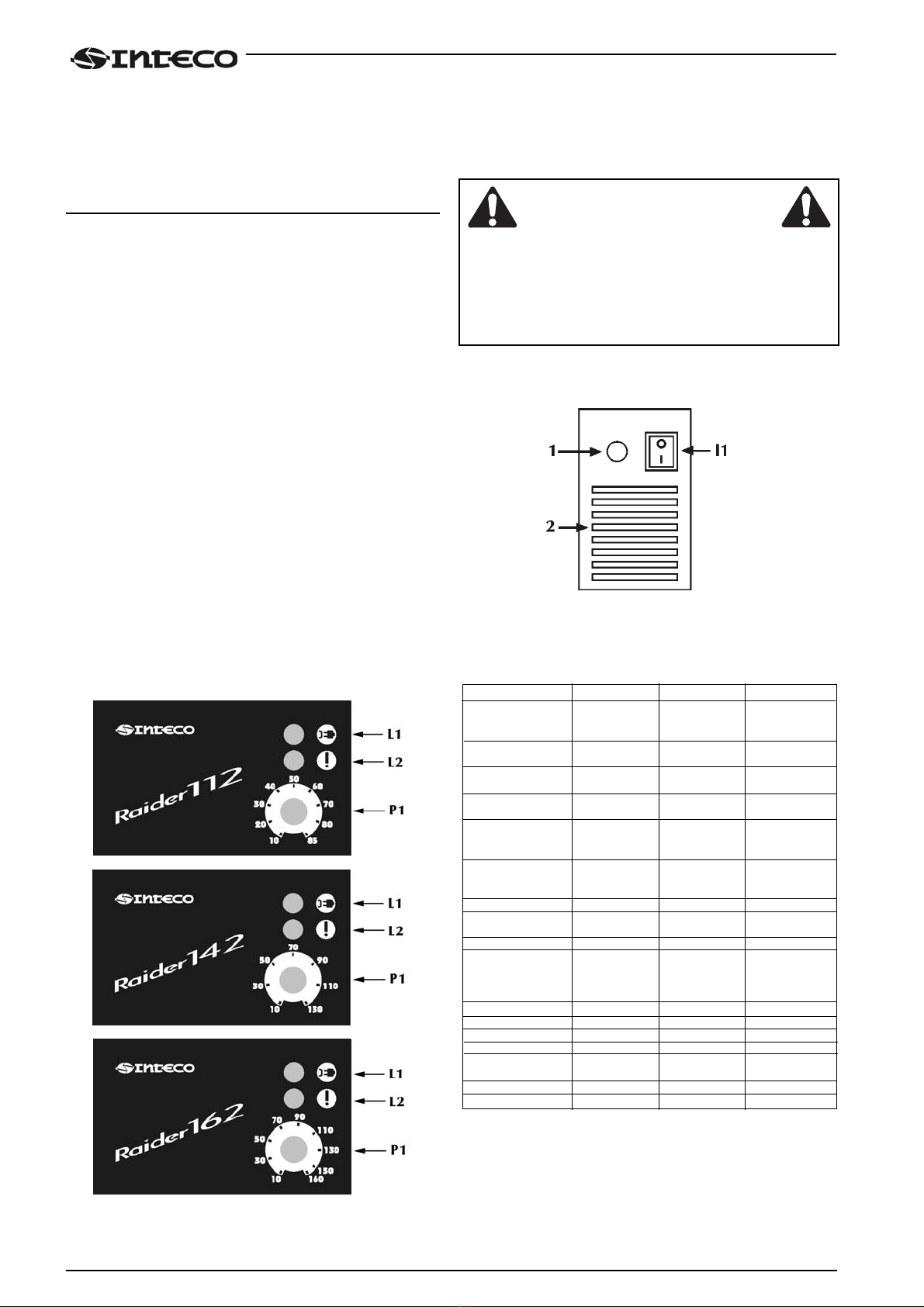
4.1 Pannello comandi frontale
*L1 : Spia presenza tensione led verde.
Si illumina con l'interruttore di accensione sul pannello
posteriore (Fig. 2) "I1" in posizione "I". E' indice di impianto
acceso e in tensione.
*L2: Spia dispositivo di protezione led giallo.
Indica l'avvenuto intervento del dispositivo di protezione
termica. Con "L2" acceso il generatore rimane collegato alla
rete ma non fornisce potenza in uscita. "L2" rimane acceso
fino a quando non sono state ripristinate le normali condizio-
ni di funzionamento.
*P1 : Potenziometro di impostazione corrente di saldatura.
Permette di regolare con continuità la corrente di saldatura.
Tale corrente resta invariata durante la saldatura quando le
condizioni di alimentazione e di saldatura variano dentro i
range dichiarati nelle caratteristiche tecniche.
In MMA la presenza di HOT-START ed ARC-FORCE fa si che
la corrente media in uscita possa essere più elevata di quella
impostata.
Fig.1
4.2 Pannello comandi posteriore
*I1 : Interruttore di accensione.
Comanda l'accensione elettrica della saldatrice.
Ha due posizioni "O" spento; "I" acceso.
*Con I1 nella posizione "I" acceso , la saldatrice è operativa
e presenta tensione tra le prese positivo (+) e negativo (-).
*La saldatrice collegata alla rete anche se con I1 nella posi-
zione "O", presenta parti in tensione al suo interno.
Attenersi scrupolosamente alle avvertenze presentate da
questo manuale.
*1 : Cavo di alimentazione.
*2 : Feritoie di ventilazione. Si raccomanda di non ostruirle.
Fig.2
4.3 Caratteristiche tecniche
RAIDER 112 RAIDER 142 RAIDER 162
Tensione di
alimentazione 1x115V / 230V 1x230V 1x230V
(50/60 Hz) ± 15% ± 15% ± 15%
Potenza massima
assorbita (x=20%) 2.76 kW 4.48 kW (x=25%) 5.49 kW (Io =150A)
Corrente massima
assorbita 33.3A / 18.7A 28.6A 34.4A (Io =150A)
Corrente assorbita
(x=100%) 18.9A / 10.1A 13.4A 17.8A
Corrente assorbita
con elettrodo 12.5A / 8.46A 10.4A 12.1A
2.50 (80 A) (x=25%) (x=40%) (X=40%)
Corrente assorbita
con elettrodo
3.25 (110 A x=40%) / 14.7A 14.6A
Rendimento (x=100%) 0.80 0.80 0.78
Fattore di potenza
(x=100%) 0.661 / 0.586 0.635 0.665
Cosϕ0.99 0.99 0.99
Corrente di saldatura
(x=20%) 85A 130A (x=25%) 150A
(x=60%) 70A 90A 100A
(x=100%) 50A 70A 90A
Gamma di regolazione 10-85A 10-130A 10-160A
Tensione a vuoto 105V 105V 105V
Grado di protezione IP21S IP21S IP21S
Classe di isolamento H H H
Norme di costruzione EN60974-1 EN60974-1 EN60974-1
EN60974-10 EN60974-10 EN60974-10
Dimensioni (lxpxh) 128x315x242mm 128x315x242mm 128x315x242mm
Peso 4.7Kg 4.7Kg 4.7Kg
Dati a 25°C di temperatura ambiente
6
ATTENZIONE

5.0 TRASPORTO - SCARICO
Non sottovalutare il peso dell'impianto, vedere
caratteristiche tecniche.
Non far transitare o sostare il carico sospeso
sopra a persone o cose.
Non lasciare cadere o appoggiare con forza l'im-
pianto o la singola unità.
Una volta tolto l'imballo, il generatore è fornito di
una cinghia che ne permette la movimentazione a
mano.
6.0 INSTALLAZIONE
Scegliere l'ambiente adeguato seguendo le indica-
zioni delle sezioni “1.0 SICUREZZA” e “2.0 COM-
PATIBILITA’ ELETTROMAGNETICA (EMC)”.
Non posizionare mai il generatore e l'impianto su
di un piano con inclinazione maggiore di 10° dal
piano orizzontale. Proteggere l'impianto contro la
pioggia battente e contro il sole.
6.1 Allacciamento elettrico alla rete
L'impianto è dotato di un unico allacciamento elettrico con cavo
di 2m posto nella parte posteriore del generatore.
Tabella dimensionamento del cavi e dei fusibili in ingresso al
generatore:
Tensione nominale 115 V ± 15% 230 V ± 15%
Range di tensione 98 - 133 V 195,5 - 264,5 V
Fusibili ritardati* 16 A 250 V 16 A 250 V
Cavo alimentazione 3x1,5 mm2 3x1,5 mm2
*:Fusibili da 20 A sono richiesti per poter saldare in elettrodo a
100 A continuamente e per utilizzare al massimo le potenzia-
lità del generatore. Fusibili da 16 A sono sufficienti per salda-
re, con un normale fattore di utilizzo (40%).
* L'impianto elettrico deve essere realizzato da personale
tecnico in possesso di requisiti tecnico-professionali spe-
cifici e in conformità alle leggi dello stato in cui si effettua
l'installazione.
* Il cavo rete della saldatrice è fornito di un filo giallo/verde,
che deve essere collegato SEMPRE al conduttore di prote-
zione a terra. Questo filo giallo/verde non deve MAI es-
sere usato insieme ad altro filo per prelievi di tensione.
* Controllare l'esistenza della "messa a terra" nell'impianto
utilizzato ed il buono stato della presa di corrente.
* Montare solo spine omologate secondo le normative di
sicurezza.
6.2 Collegamento attrezzature
Attenersi alle norme di sicurezza riportate nella
sezione “1.0 SICUREZZA”.
Collegare accuratamente le attrezzature per evita-
re perdite di potenza.
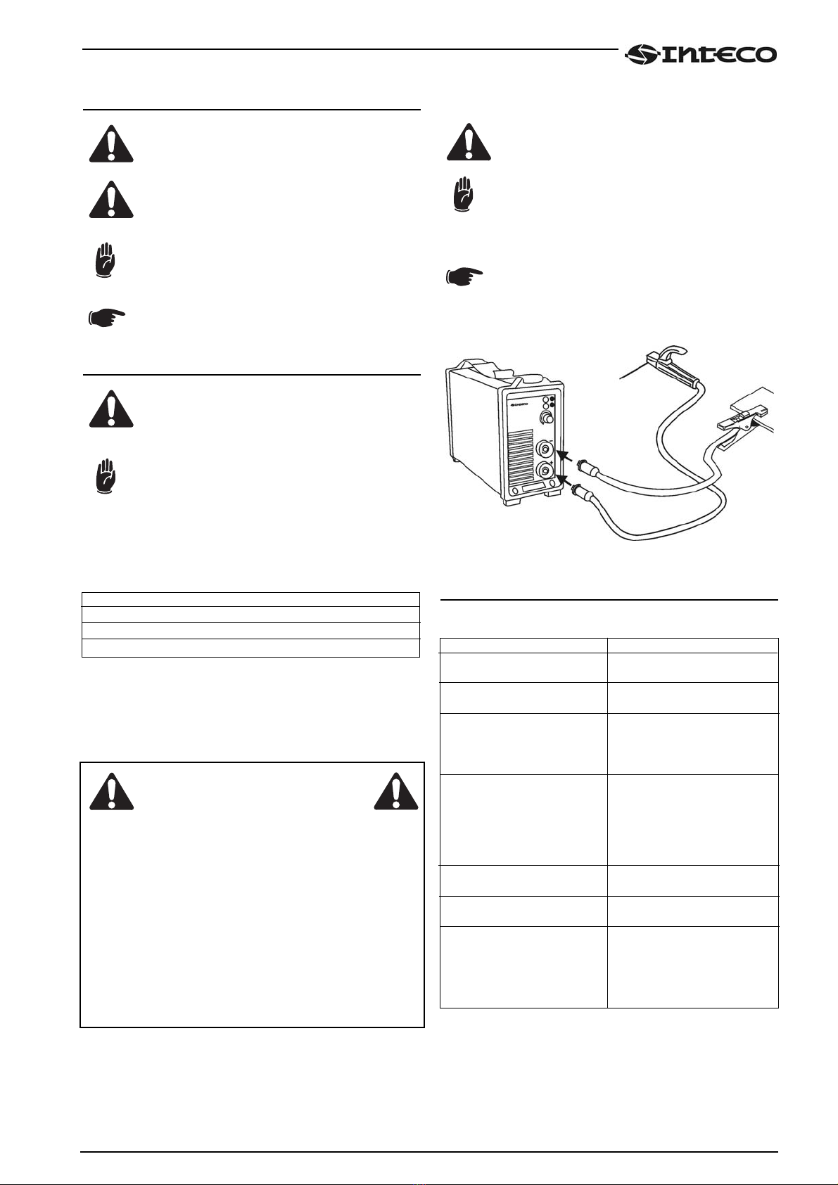
Collegamento per saldatura MMA (Fig. 3)
Il collegamento in figura dà come risultato una sal-
datura con polarità inversa. Per ottenere una salda-
tura con polarità diretta, invertire il collegamento.
Fig.3
7.0 PROBLEMI-CAUSE
7.1 Possibili difetti di saldatura in MMA
7
ATTENZIONE
Problema
Spruzzi eccessivi
Crateri
Inclusioni
Insufficiente penetrazione
Incollature
Soffiature e porosità
Cricche
Causa
1) Arco lungo.
2) Corrente elevata.
1) Allontanamento rapido
dell'elettrodo in staccata.
1) Cattiva pulizia o distribu-
zione delle passate.
2) Movimento difettoso del-
l'elettrodo.
1) Velocità di avanzamento
elevata.
2) Corrente di saldatura
troppo bassa.
3) Cianfrino stretto.
4) Mancata scalpellatura al
vertice.
1) Arco troppo corto
2) Corrente troppo bassa
1) Umidità nell'elettrodo
2) Arco lungo
1) Correnti troppo elevate
2) Materiali sporchi
3) Idrogeno in saldatura
(presente sul rivestimento
dell'elettrodo)

8
7.2 Possibili inconvenienti elettrici
Per ogni dubbio e/o problema non esitare a consultare il più
vicino centro di assistenza tecnica .
8.0 MANUTENZIONE ORDINARIA NECESSARIA
Evitare che si accumuli polvere metallica in prossimità e sulle
alette di areazione.
Togliere l'alimentazione all'impianto prima di
ogni intervento!
Controlli periodici al generatore:
* Effettuare la pulizia interna utilizzando aria com-
pressa a bassa pressione e pennelli a setola mor-
bida.
* Controllare le connessioni elettriche e tutti i cavi
di collegamento.
* Controllare la temperatura dei componenti ed accertarsi
che non siano surriscaldati.
* Utilizzare sempre guanti a normativa.
* Utilizzare chiavi ed attrezzi adeguati.
Nota: In mancanza di detta manutenzione, decadranno tutte
le garanzie e comunque il costruttore viene sollevato da
qualsiasi responsabilità.
9.0 INFORMAZIONI GENERALI SULLE
SALDATURE
9.1 Saldatura con elettrodo rivestito (MMA)
Preparazione dei lembi
Per ottenere buone saldature è sempre consigliabile operare su
parti pulite, libere da ossido, ruggine o altri agenti contaminanti.
Scelta dell'elettrodo
Il diametro dell'elettrodo da impiegare dipende dallo spessore
del materiale, dalla posizione, dal tipo di giunto e dal tipo di
cianfrino.
Elettrodi di grosso diametro richiedono correnti elevate con
conseguente elevato apporto termico nella saldatura.
Scelta della corrente di saldatura
Il range della corrente di saldatura relativa al tipo di elettrodo
impiegato viene specificato dal costruttore sul contenitore stes-
so degli elettrodi.
Accensione e mantenimento dell'arco
L'arco elettrico si stabilisce sfregando la punta dell' elettrodo sul
pezzo da saldare collegato al cavo massa e, una volta scoccato
l'arco, ritraendo rapidamente la bacchetta fino alla distanza di
normale saldatura.
Per migliorare l'accensione dell'arco è utile, in generale, un
incremento iniziale di corrente rispetto alla corrente base di sal-
datura (Hot Start).
Una volta instauratosi l'arco elettrico inizia la fusione della parte
centrale dell'elettrodo che si deposita sotto forma di gocce sul
pezzo da saldare.
Il rivestimento esterno dell'elettrodo fornisce, consumandosi, il
gas protettivo per la saldatura che risulta così di buona qualità.
Per evitare che le gocce di materiale fuso, cortocircuitando l'e-
lettrodo col bagno di saldatura, a causa di un accidentale avvi-
cinamento tra i due, provochino lo spegnimento dell'arco è
molto utile un momentaneo aumento della corrente di saldatu-
ra fino al termine del cortocircuito (Arc Force).
Nel caso in cui l'elettrodo rimanga incollato al pezzo da saldare è
utile ridurre al minimo la corrente di cortocircuito (antisticking).
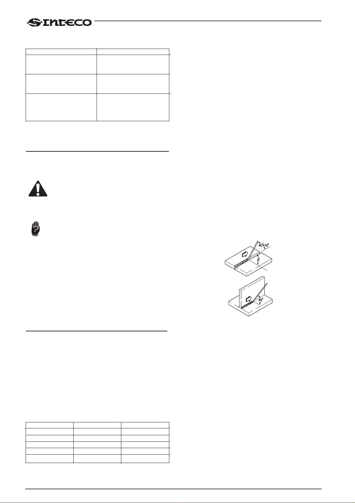
Esecuzione della saldatura
L'angolo di inclinazione dell'elettrodo varia a seconda del numero
delle passate, il movimento dell'elettrodo viene eseguito normal-
mente con oscillazioni e fermate ai lati del cordone in modo da
evitare un accumulo eccessivo di materiale d'apporto al centro.
Fig. 4
Asportazione della scoria
La saldatura mediante elettrodi rivestiti impone l'asportazione
della scoria successivamente ad ogni passata.
L'asportazione viene effettuata mediante un piccolo martello o
attraverso la spazzolatura nel caso di scoria friabile.
Difetto
Mancata accensione della
macchina. (Led verde spento)
Erogazione di potenza non
corretta. (LED verde acceso)
Assenza di corrente in uscita.
(Led verde acceso)
Causa
1) Tensione non presente
sulla presa di alimenta-
zione.
2) Spina o cavo di alimenta-
zione difettoso.
1) Tensione di rete bassa.
2) Potenziometro regolazione
di corrente difettoso.
1) Apparecchio surriscaldato
(Led giallo acceso).
Attendere raffreddamento
con saldatrice accesa.
Tipo di rivestimento
Rutilo
Acido
Basico
Acciaio
Ghisa
Proprietà
Facilità d'impiego
Alta velocità fusione
Caratt. meccaniche
Per acciaio
Per ghisa
Impiego
Tutte le posizioni
Piano
Tutte le posizioni
Tutte le posizioni
Tutte le posizioni
ENGLISH
USE AND MAINTENANCE MANUAL
This manual is an integral part of the unit or machine and must accompany it when it changes location or is resold.
The user must assume responsibility for maintaining this manual intact and legible at all times.
SELCO s.r.l. Division INTECO reserves the right to modify this manual at any time without notice.
All rights of translation and total or partial reproduction by any means whatsoever (including photocopy, film, and microfilm) are reser-
ved and reproduction is prohibited without the express written consent of SELCO s.r.l. Division INTECO.
Edition ‘04
CONFORMITY CERTIFICATE CE
Company
SELCO s.r.l. Division INTECO - Via Palladio, 19 - 35010 ONARA DI TOMBOLO (Padova) - ITALY
Tel. +39 049 5993617 - Fax +39 049 9413306
hereby declares that the apparatus type RAIDER 112
RAIDER 142
RAIDER 162
to which this declaration pertains conforme to the : 73/23/CEE
89/336 CEE
92/31 CEE
93/68 CEE
and that the regulations have been duly applied : EN 60974-10
EN 60974-1
Any operation or modification that has not been previously authorized by SELCO s.r.l. Division INTECO shall invalidate this certificate.
Onara di Tombolo (PADOVA) Legal representative
Lino Frasson
CONTENTS
9
1.0 SAFETY . . . . . . . . . . . . . . . . . . . . . . . . . . . . . . . . .10
1.1 Operator and other persons’ protection . . . . . . .10
1.2 Fire/explosion prevention . . . . . . . . . . . . . . . . .10
1.3 Protection against fumes and gases . . . . . . . . . .10
1.4 Positioning the power source . . . . . . . . . . . . . . .10
1.5 lnstalling the apparatus . . . . . . . . . . . . . . . . . . .10
2.0 ELECTROMAGNETIC COMPATIBILITY (EMC) . . . .11
2.1 Installation, use and area examination . . . . . . . .11
2.2 Emission reduction methods . . . . . . . . . . . . . . .11
3.0 RISK ANALYSIS . . . . . . . . . . . . . . . . . . . . . . . . . . .11
4.0 MACHINE DESCRIPTION . . . . . . . . . . . . . . . . . . .12
4.1 Front control panel . . . . . . . . . . . . . . . . . . . . .12
4.2 Rear control panel . . . . . . . . . . . . . . . . . . . . . .12
4.3 Technical characteristics . . . . . . . . . . . . . . . . . .12
5.0 TRANSPORT - UNLOADING . . . . . . . . . . . . . . . . .13
6.0 INSTALLATION . . . . . . . . . . . . . . . . . . . . . . . . . . .13
6.1 Electric connection to the supply mains . . . . . . .13
6.2 Connecting the equipment components . . . . . . .13
7.0 PROBLEMS - CAUSES . . . . . . . . . . . . . . . . . . . . . .13
7.1 Possible faults in the MMA welding . . . . . . . . . .13
7.2 Possible electrical failures . . . . . . . . . . . . . . . .14
8.0 NECESSARY ORDINARY MAINTENANCE . . . . . . . .14
9.0 GENERAL INFORMATION ON THE
DIFFERENT WELDING PROCESSES . . . . . . . . . . . . . .14
9.1 Coated electrode welding (MMA) . . . . . . . . . .14
SYMBOLS
lmminent danger of serious bodily harm and
dangerous behaviours that may lead to serious
bodily harm.
lmportant advice to be followed in order to avoid
minor injuries or damage to property.
The notes preceded by this symbol are mainly
technical and facilitate operations.
1.0 SAFETY
Prior to performing any operation on the machine, make sure
that you have thoroughly read and understood the contents of
this manual.
Do not perform modifications or maintenance operations which
are not prescribed.
For any doubt or problem regarding the use of the machine,
even if not described herein, consult qualified personnel.
The productor cannot be held responsible for damage to per-
sons or property caused by the operator's failure to read or
apply the contents of this manual.
1.1 Operator and other persons' protection
The welding process is a noxious source of radiations, noise,
heat and gas emissions. The persons fitted with vital electronic
devices (pacemakers) should consult a doctor before attending
any arc welding or plasma arc cutting operation.
Personal protection:
- Do not wear contact lenses!!!
- Keep a first aid kit ready for use.
-Do not underestimate any burning or injury.
- Wear protective clothing to protect your skin from the arc rays,
sparks or incandescent metal, and a helmet or a welding cap.
- Wear masks with side face guards and suitable protection fil-
ter (at least NR10 or above) for the eyes.
- Use headphones if dangerous noise levels are reached
during the welding.
Always wear safety goggles with side guards, especially
during the manual or mechanical removal of welding slags.
lf you feel an electric shock, interrupt the welding ope-
rations immediately.
Other persons' protection:
- Position a fire-retardant partition to protect the surroun-
ding area from rays, sparks and incandescent slags.
- Advise any person in the vicinity not to stare at the arc or at
the incandescent metal and to get an adequate protection.
- lf the noise level exceeds the limits prescribed by the law,
delimit the work area and make sure that anyone getting
near it is protected with headphones or earphones.
1.2 Fire/explosion prevention
The welding process may cause fires and/or explosions.
- Compressed gas cylinders are dangerous; consult the supplier
before handling them.
Protect them from:
- direct exposure to sun rays;
- flames;
- sudden changes in temperature;
- very low temperatures.
Compressed gas cylinders must be fixed to the walls or to
other supports, in order to prevent them from falling.
- Clear the work area and the surrounding area from any
infiammable or combustible materials or objects.
- Position a fire-fighting device or material near the work
area.
-
- Do not perform welding or cutting operations on closed
containers or pipes.
- lf said containers or pipes have been opened, emptied and
carefully cleaned, the welding operation must in any case be
performed with great care.
- Do not weld in places where explosive powders, gases or
vapours are present.
- Do not perform welding operations on or near containers
under pressure.
- Don’t use this machine to defrost pipes.
1.3 Protection against fumes and gases
Fumes, gases and powders produced during the welding pro-
cess can be noxious for your health.
-Do not use oxygen for the ventition.
- Provide for proper ventilation, either natural or forced, in the
work area.
- In case of welding in extremely small places the work of the
operator carrying out the weld should be supervised by a col-
league standing outside.
- Position gas cylinders outdoors or in places with good ventila-
tion.
- Do not perform welding operations near degreasing or
painting stations.
1.4 Positioning the power source
Keep to the following rules:
- Easy access to the equipment controls and connections
must be provided.
- Do not position the equipment in reduced spaces.
- Do not place the generator on surfaces with inclination
exceeding 10° with respect to the horizontal plane.
1.5 lnstalling the apparatus
- Comply with the local safety regulations for the installation
and carry out the maintenance service of the machine accor-
ding to the constructor's directions.
- Any maintenance operation must be performed by qua-
lified personnel only.
- The connection (series or parallel) of the generators is prohi-
bited.
- Before operating inside the generator, disconnect the
power supply.
- Carry out the routine maintenance on the equipment.
- Make sure that the supply mains and the earthing are suffi-
cient and adequate.
- The earth cable must be connected as near the area to be
welded as possible.
- Take the precautions relevant to the protection degree of the
power source.
- Before welding, check the condition of the electric cables and
of the torch, and if they are damaged repair or change them.
- Neither get on the material to be welded, nor lean against it.
-The operator must not touch two torches or two electrode
holders at the same time.
The manufacturer accepts no liability if the above prescrip-
tion is not duly observed and complied with at all times.
10
WARNING

2.0 ELECTROMAGNETIC COMPATIBILITY (EMC)
This device is built in compliance with the indications contained
in the harmonized standard EN60974-10, to which the opera-
tor must refer for the use of this apparatus.
- lnstall and use the apparatus keeping to the instructions
given in this manual.
- This device must be used for professional applications
only, in industrial environments It is important to remem-
ber that it may be difficult to ensure the electromagnetic
compatibility in other environments.
2.1 Installation, use and area examination
- The user is responsible for the installation and use of the
equipment according to the manufacturer's instructions.
lf any electromagnetic disturbance is noticed, the user must
soave the problem, if necessary with the manufacturer's tech-
nical assistance.
- In any case electromagnetic disturbances must be reduced
until they are not a nuisance any longer.
- Before installing this apparatus, the user must evaluate the
potential electromagnetic problems that may arise in the
surrounding area, considering in particular the health con-
ditions of the persons in the vicinity, for example of per-
sons fitted with pacemakers or hearing aids.
2.2 Emission reduction methods
MAINS POWER SUPPLY
- The welding power source must be connected to the
supply mains according to the manufacturer's instructions.
In case of interference, it may be necessary to take further pre-
cautions like the filtering of the mains power supply.
lt is also necessary to consider the possibility to shield the power
supply cable.
WELDING POWER SOURCE MAINTENANCE
The welding power source needs routine maintenance accor-
ding to the manufacturer's instructions.
When the equipment is working, all the access and operating
doors and covers must be closed and fixed.
The welding power source must not be modified in any way.
WELDING AND CUTTING CABLES
The welding cables must be kept as short as possible, positioned
near one another and laid at or approximately at ground level.
EQUIPOTENTIAL CONNECTION
The earth connection of all the metal componente in the wel-
ding installation and near it must be taken in consideration.
However, the metal componente connected to the work-piece
will increase the risk of electric shock for the operator, if he tou-
ches said metal componente and the electrode at the same
time.
Therefore, the operator must be insulated from all the earthed
metal componente.
The equipotential connection must be made according to the
national regulations.
EARTHING THE WORKPIECE
When the workpiece is not earthed for electrical safety reasons
or due to its size and position, the earthing of the workpiece
may reduce the emissione. It is important to remember that the
earthing of the workpiece should neither increase the risk of
accidents for the operators, nor damage other electric equip-
ment.
The earthing must be made according to the national regula-
tions.
SHIELDING
The selective shielding of other cables and equipment present
in the surrounding area may reduce the problems due to inter-
ference. The shielding of the entire welding installation can be
taken in consideration for special applications.
3.0 RISK ANALYSIS
11
WARNING
Risks posed by the machine
Risk of wrong installation.
Electrical risks.
Risks connected with electromagnetic disturbances produced
by the welding power source and induced on the welding
power source.
Solutions adopted to pervent them
A manual with the instructions for use has been pro-
duced for this purpose.
Application of the EN 60974-1 Standard.
Application of the EN 60974-10 Standard.

The contents of this chapter are of vital importance and the-
refore necessary for operation of the warranties. The manu-
facturer accepts no liability if the operator fails to observe
the above precautions and instructions.
4.0 MACHINE DESCRIPTION
These power sources are purposely designed for MMA welding.
The innovative inverter technology ensures top level perfor-
mance with very low absorption.
The generator is equipped with:
- positive (+) and negative (-) socket;,
- front panel,
- rear control panel
4.1 Front control panel
*L1 : Voltage warning light green led.
Comes on with the start switch (Fig.2) "I1" in position "I" and
indicates that the plant is on and there is voltage.
*L2 : Safety device warning light yellow led.
lndicates that the safety devices like thermal cutout.
With "L2" on, the power source remains connected to the
supply mains, but does not supply output power.
"L2" remains on until normal operating conditions have been
restored.
*P1: Potentiometer for setting the welding current
Allows you to continuously adjust the current both. This current
stays unchanged when the supply and welding conditions vary
within the allowed ranges.
In MMA welding, the presence of HOT-START and ARC-
FORCE means that the average output current may be
higher than that set.
Fig.1
4.2 Rear control panel
*I1: Off/On switch
Turns on the electric power to the welder.
It has two positions, "O" off, and "I" on.
*With the I1 switch in the "I" on position, the welder is
operational, and gives a voltage between the positive (+)
and negative (-) clamps.
*The welder is connected to the mains supply even if the I1
switch is in the "O" position, and therefore there are elec-
trically live parts inside it. Carefully follow the instruc-
tions given in this manual.
*1 : Supply cable
*2 : Ventilation slots. Never allow them to be obstructed.
Fig.2
4.3 Technical characteristics
RAIDER 112 RAIDER 142 RAIDER 162
Power supply voltage 1x115V / 230V 1x230V 1x230V
(50/60 Hz) ± 15% ± 15% ± 15%
Max. absorbed power
(x=20%) 2.76 kW 4.48 kW (x=25%) 5.49 kW (Io =150A)
Max. absorbed current 33.3A / 18.7A 28.6A 34.4A (Io =150A)
Absorbed current
(x=100%) 18.9A / 10.1A 13.4A 17.8A
Absorbed current with
2.50 electrode (80 A) 12.5A / 8.46A 10.4A 12.1A
(x=25%) (x=40%) (X=40%)
Absorbed current with
3.25 electrode
(110 A x=40%) / 14.7A 14.6A
Efficiency (x=100%) 0.80 0.80 0.78
Power factor (x=100%) 0.661 / 0.586 0.635 0.665
Cosϕ0.99 0.99 0.99
Welding current
(x=20%) 85A 130A (x=25%) 150A
(x=60%) 70A 90A 100A
(x=100%) 50A 70A 90A
Adjustment range 10-85A 10-130A 10-160A
Open-circuit voltage
(limited) 105V 105V 105V
Protection rating IP21S IP21S IP21S
lnsulation class H H H
Construction standards EN60974-1 EN60974-1 EN60974-1
EN60974-10 EN60974-10 EN60974-10
Dimensions (lxdxh) 128x315x242mm 128x315x242mm 128x315x242mm
Weight 4.7Kg 4.7Kg 4.7Kg
Above data are referred to environment al 25°C
12
WARNING

5.0 TRANSPORT - UNLOADING
Never underestimate the weight of the equip-
ment, see technical characteristics.
Never make the cargo pass or leave it suspended
over people or things.
Neither let the equipment or the single unit fall,
nor put it down with force.
Once it has been removed from the packing, the
power source is supplied with an belt which can be
used to move it in the hand.
6.0 INSTALLATION
Choose an adequate installation area by following
the criteria provided in Section "1.0 SAFETY" and
“2.0 ELECTROMAGNETIC COMPATIBILITY (EMC)”.
Do not position the power source and the equip-
ment on surfaces with inclination exceeding 10°
with respect to the horizontal plane.
Protect the installation from heavy rain and sun.
6.1 Electric connection to the supply mains
The equipment is provided with a single electric connection with
a 2m cable positioned in the rear part of the power source.
Size table of the power source input cables and fuses:
Rated voltage 115 V ± 15% 230 V ± 15%
Voltage range 98 - 133 V 195,5 - 264,5 V
Delayed fuses* 16 A 250 V 16 A 250 V
Power supply cable 3x1,5 mm2 3x1,5 mm2
*:Fuses with a 20A rating are required to be able to carry out
100 A electrode welding continuously and to make maximum
use of the potential of the power source. 16 A fuses are suffi-
cient for welding, with a normal use factor (40%).
* The electrical system must be made by skilled technicians
with the specific professional and technical qualifications
and in compliance with the regulations in force in the
country where the equipment is installed.
* The welding power source supply cable is provided with a
yellow/green wire that must ALWAYS be earthed. This yel-
low/green wire must NEVER be used with other voltage
conductors.
* Verity the existence of the earthing in the used plant and
the good condition of the socket/s
* lnstall only plugs that are homologated according to
the safety regulations.
6.2 Connecting the equipment components
Keep to the safety regulations contalned in section
“1.0 SAFETY”.
Connect the componente carefully, in order to
avoid power losses.
Connection for MMA welding
The connection shown in the figure produces
reverse polarity welding. To obtain straight polarity
welding, invert the connection.
Fig.3
7.0 PROBLEMS - CAUSES
7.1 Possible faults in the MMA welding
WARNING
13
Fault
Excessive spatter
Craters
Inclusions
Insufficient penetration
Sticking
Blow-hole and porosity
Cracks
Cause
1) Long arc
2) High current
1) Fast movement of the
electrode away from piece.
1) Poor cleanliness or distri-
bution of the passes
2) Defective movement of
the electrode
1) High progression speed
2) Welding current too low
3) Narrow chamfering
4) Deseaming failure on top
1) Arc too short
2) Current too low
1) Humidity in electrode
2) Long arc
1) Current too high
2) Dirty materials
3) Hydrogen in weld
(present on electrode
coating)
14
7.2 Possible electrical failures
If you have any doubts or problems, do not hesitate to con-
sult your nearest technical service centre.
8.0 NECESSARY ORDINARY MAINTENANCE
Prevent metal powder from accumulating near the aeration fins
and over them.
Disconnect the power supply before every opera-
tion!
Carry out the following periodic controls on the
power source:
* Clean the power source inside by means of low-
pressure compressed air and soft bristel brushes.
* Check the electric connections and all the connec-
tion cables.
* Check the temperature of the componente and make
sure that they are not overheated.
* Always use gloves in compliance with the safety stan-
dards.
* Use suitable spanners and tools.
NOTE: Failure to perform said maintenance will invalidate all
warranties and exempt the manufacturer from all liability.
9.0 GENERAL INFORMATION ON THE
DIFFERENT WELDING PROCESSES
9.1 Coated electrode welding (MMA)
Preparing the edges
To obtain good welding joints it is advisable to work on clean
parts, free from oxidations, rust or other contaminating agents.
Choosing the electrode
The diameter of the electrode to be used depends on the thick-
ness of the material, the position, the type of joint and the type
of preparation of the piece to be welded.
Electrodes with considerable diameter obviously require very
high currents with consequent high heat supply during the wel-
ding.
Choosing the welding current
The range of welding current in relation to the type of electrode
used is specified by the manufacturer on the electrode container.
Striking and maintaining the arc
The electric arc is produced by rubbing the electrode point on
the workpiece connected to the earth cable and, once the arc
has been striken, by rapidly withdrawing the rod to the normal
welding distance.
Generally, to improve the striking of the arc an initial current
increase with respect to the base welding current is very useful
(Hot Start).
Once the arc has been striken, the central part of the electrode
starts melting and is deposited on to the workpiece in the form
of drops.
The external coating of the electrode is consumed and this sup-
plies the protective gas for the welding, the good quality of
which is thus ensured.
To prevent the molten material drops from extinguishing the arc
by short-circuiting the electrode with the weld pool because of
their accidental proximity to each other, a temporary increase of
the welding current until the end of the short-circuit is very use-
ful (Arc Force).
If the electrode sticks to the piece to be welded, it is useful to
minimise the short circuit current (antisticking).
Carrying out the welding
The electrode inclination angle varies depending on the number
of runs; the electrode movement is normally carried out with
oscillations and stops at the sides of the bead, in such a way as to
avoid an excessive accumulation of filler material at the centre.
Fig.4
Removing the slag
The welding through coated electrodes requires the removal of
the slag after each run.
The slag is removed by means of a small hammer or is brushed
away if friable.
Fault
Machine fails to come on
(Green LED off)
Power output incorrect
(Green LED on)
Absence of output current
(Green LED on)
Cause
1) No current in the power
socket.
2) Faulty supply plug or cable.
1) Low mains supply voltage.
2) Faulty current control
potentiometer.
1) Equipment overheated
(yellow LED on).
With welder on, wait for it
to cool.
Type of coating
Rutile
Acid
Basic
Steel
Cast iron
Property
Ease of use
High melting speed
Mechanical charact.
For steel
For cast iron
Use
All positions
Flat
All positions
All positions
All positions

DEUTSCH
GEBRAUCHS-UND WARTUNGSANLEITUNG
Dieses Anleitungsheft ist ein integrierender Bestandteil der Einheit bzw. der Maschine und muß daher bei einer Verlagerung oder
beim Wiederverkauf derselben immer mitgeliefert werden.
Der Benutzer wird dafür sorgen, das Anleitungsheft intakt und in gutem Zustand aufzubewahren.
Die Firma SELCO s.r.l. Division INTECO behält sich das Recht vor, jederzeit und ohne Vorankündigung Änderungen vor-
zunehmen.
Vorbehalten und ohne schriftliche Genehmigung seitens der Firma SELCO s.r.l. Division INTECO verboten sind Übersetzungs-,
Nachdruck- und Bearbeitungsrechte, ob ganzheitlich oder auszugsweise und mit welchen Mitteln (einschließlich Fotokopien, Filme
und Mikrofilme) sie auch durchgeführt werden.
Ausgabe ‘04
KONFORMITÄTSERKLÄRUNG CE
Die Firma
SELCO s.r.l. Division INTECO - Via Palladio, 19 - 35010 ONARA DI TOMBOLO (Padova) - ITALY
Tel. +39 049 5993617 - Fax +39 049 9413306
erklärt, daß das Gerät Typ RAIDER 112
RAIDER 142
RAIDER 162
den folgenden Richtlinien entspricht: 73/23/CEE
89/336 CEE
92/31 CEE
93/68 CEE
und daß folgende die Normen angewendet wurden: EN 60974-10
EN 60974-1
Jede von der Firma SELCO s.r.l. Division INTECO nicht genehmigte Änderung hebt die Gültigkeit dieser Erklärung auf.
Onara di Tombolo (PADOVA) Rechtlicher Vertreter
Lino Frasson
INHALTSVERZEICHNIS
15
1.0 SICHERHEIT . . . . . . . . . . . . . . . . . . . . . . . . . . . . .16
1.1 Persönlicher Schutz und Schutz Dritter . . . . . . .16
1.2 Brand-/Explosionsverhütung . . . . . . . . . . . . . . .16
1.3 Rauch- und Gasschutz . . . . . . . . . . . . . . . . . . .16
1.4 Generator aufstellen . . . . . . . . . . . . . . . . . . . . .16
1.5 Gerät installieren . . . . . . . . . . . . . . . . . . . . . . .16
2.0 ELEKTROMAGNETISCHE VERTRÄGLICHKEIT
(EMC) . . . . . . . . . . . . . . . . . . . . . . . . . . . . . . . . . .17
2.1 lnstallation, Gebrauch und Bewertung
des Bereichs . . . . . . . . . . . . . . . . . . . . . . . . . . .17
2.2 Systeme zur Reduzierung der Emissionen . . . . . .17
3.0 GEFAHRENANALYSE . . . . . . . . . . . . . . . . . . . . . . .17
4.0 VORSTELLUNG DER MASCHINE . . . . . . . . . . . . .18
4.1 Vorderes Schaltfeld . . . . . . . . . . . . . . . . . . . . .18
4.2 Hinteres Schaltfeld . . . . . . . . . . . . . . . . . . . . . .18
4.3 Technische Eigenschaften . . . . . . . . . . . . . . . . .18
5.0 TRANSPORT - ABLADEN . . . . . . . . . . . . . . . . . . . .19
6.0 INSTALLATION . . . . . . . . . . . . . . . . . . . . . . . . . . .19
6.1 Elektrischer anschluss an das netz . . . . . . . . . . .19
6.2 Anschlüsse . . . . . . . . . . . . . . . . . . . . . . . . . . .19
7.0 STÖRUNGEN - URSACHEN . . . . . . . . . . . . . . . . .19
7.1 Mögliche Fehler Bei MMA -Schweissung . . . . . .19
7.2 Mögliche Elektrische Störungen . . . . . . . . . . . . .20
8.0 NOTWENDIGE GEWÖHNLICHE
WARTUNG . . . . . . . . . . . . . . . . . . . . . . . . . . . . . . . . .20
9.0 ALLGEMEINE INFORMATIONEN
ZU DEN SCHWEISSUNGEN . . . . . . . . . . . . . . . . .20
9.1 Schweißen mit Mantelelektroden (MMA) . . . . .20
SYMBOLE
Drohende Gefahren, die schwere Verletzungen
verursachen, und gefährliche Verhaltensweisen,
die schwere Verletzungen verursachen könnten.
Verhaltensweisen, die leichte Verletzungen oder
Sachschäden verursachen könnten.
Die mit diesem Symbol gekennzeichneten An-
merkungen sind technischer Art und erleichtern
die Arbeitsschritte.
1.0 SICHERHEIT
Vor Arbeitsbeginn sollten Sie das Anleitungsheft sorgfältig durch-
lesen und sich vergewissern, ob Sie alles richtig verstanden
haben. Nehmen Sie keine Änderungen vor und führen keine
hier nicht beschriebenen Instandhaltungsarbeiten durch. In
Zweifelsfällen oder wenn bei der Anwendung der Maschine
Probleme auftreten sollten, die hier nicht beschrieben sind,
wenden Sie sich an das Fachpersonal.
Die Firma der Hersteller haftet nicht für Personen- oder
Sachschäden, die auf unaufmerksames Lesen bzw. auf
Nachlässigkeit bei der Durchführung der in diesem Anleitungsheft
beschriebenen Anweisungen zurückzuführen sind.
1.1 Persönlicher Schutz und Schutz Dritter
Das Schweißverfahren ist eine schädliche Quelle von
Strahlungen, Lärm, Wärme und gasförmigen Ausdünstungen.
Träger von lebenswichtigen elektronischen Geräten (Pacemaker)
sollten einen Arzt aufsuchen, bevor sie sich dem Arbeitsbereich-
Bogenschweißung oder Plasmaschneiden-nähern.
Persönlicher Schutz:
- Keine Kontaktlinsen verwenden!!!
- Einen Verbandkasten griffbereit halten.
-Verbrennungen oder Verletzungen nicht unterschätzen.
- Schutzkleidung anziehen, um die Haut vor Bogenstrahlen
und Funken bzw. vor glühend heißem Metall zu schützen,
und einen Schutzhelm oder eine Schweißerschutzhaube ver-
wenden
- Schutzschilder mit seitlichem Schutz für das Gesicht und
geeignetem Schutzfilter (mindestens NR10 oder mehr) für die
Augen verwenden.
- Ohrenschützer verwenden, wenn das Schweißverfahren zu
einer gefährlichen Lärmquelle wird.
Bei der manuellen oder mechanischen Beseitigung der
Schweißschlacken immer Schutzbrillen mit Seitenschutz
aufsetzen.
Die Schweißoperationen sofort abbrechen, wenn das
Gefühl eines elektrischen Schlags wahrgenommen wird.
Schutz Dritter
- Eine feuerhemmende Trennwand aufstellen, um den
Schweißbereich vor Strahlen, Funken und glühenden
Schlacken zu schützen.
- Die ggf. anwesenden dritten Personen darauf hinweisen,
die Bogenstrahlen bzw. das glühende Metall nicht zu fixieren
und sich davor zu schützen.
- Wenn der Geräuschpegel die gesetzlich festgelegten
Grenzen überschreitet, den Arbeitsbereich abgrenzen und
prüfen, ob die Personen, die diesen Bereich betreten,
Hauben oder Ohrenschützer tragen.
1.2 Brand-/Explosionsverhütung
Das Schweißverfahren kann Brand und/oder Explosion verursachen.
- Die Druckgasflaschen sind gefährlich; vor Anwendung den
Lieferanten zu Rate ziehen.
Die Gasdruckflaschen so aufstellen, daß sie vor:
- direkter Einwirkung der Sonnenstrahlen;
- Flammen;
- Temperaturschwankungen;
- sehr niedrigen Temperaturen geschützt sind.
Die Gasdruckflaschen mit geeigneten Vorrichtungen an
Wänden o.ä. befestigen, damit sie nicht fallen können.
- Die entzündbaren bzw. brennbaren Stoffe oder Gegenstände
aus dem Arbeitsbereich sowie aus dem umliegentile den
Bereich entfernen.
- In der Nähe des Arbeitsbereichs eine Feuerlöschvorrich-
tung aufstellen.
- Keine Schweiß- oder Schneidoperationen an geschlosse-
nen Behältern oder Rohren durchführen.
- Auch nachdem die genannten Behälter oder Rohre geöf-
fnet, entleert und sorgfältig gereinigt wurden, ist die
Scheißoperation mit größter Sorgfalt durchzuführen.
- Nicht in Räumen schweißen, die explosive Staubteile, Gase
oder Dämpfe enthalten.
- Keine Schweißungen über oder in der Nähe von Druck-
behältern ausführen.
- Bedienen sie nicht solches Gerät, um die Röhre zu entfrosten.
1.3 Rauch- und Gasschutz
Rauch, Gas und Staub, die durch das Schweißverfahren entste-
hen, können gesundheitsschädlich sein.
-Wichtiger Hinweis: keinen Sauerstoff für die Lüftung ver-
wenden.
- lm Arbeitsbereich eine angemessene natürliche Lüftung
bzw. Zwangsbelüftung vorsehen.
- Wenn Schweißungen in engen Räumen durchgeführt wer-
den, sollte der Schweißer von einem außerhalb dieses Raums
stehenden Kollegen beaufsichtigt werden.
- Die Gasflaschen im Freien oder in gut belüfteten Räumen auf-
stellen.
- Keine Schweißoperationen in der Nähe von Entfettungs-
und Lackierungsstellen durchführen.
1.4 Generator aufstellen
Folgende Vorschriften beachten:
- Leicht zugängliche Schaltungen und Anschlüsse.
- Das Gerät nicht in engen Räumen aufstellen.
- Den Generator nie auf eine Ebene mit einer Neigung von
mehr als 10° gegenüber der horizontalen Ebene aufstellen.
1.5 Gerät installieren
- Die lokalen Bestimmungen bezüglich der Sicherheitsvor-
schriften bei der lnstallation beachten und Wartung des
Gerätes gemäß Anweisungen des Herstellers ausführen.
- Die ggf. notwendige Wartung ist ausschließlich von qualifi-
ziertem Personal auszuführen.
- Die Schaltung (Reihen- oder Parallelschaltung) der Ge-
neratoren ist verboten.
- Vor jedem Eingriff im lnnern des Generators die Zuführleitung
von der Anlage trennen.
- Die Anlage regelmäßig warten.
- Prüfen, ob das Versorgungsnetz und die Erdung ausrei-
chend und angemessen sind.
- Das Massekabel muß so nah wie möglich blim zu sch-
weißenden Bereich angeschlossen werden.
- Die dem Schutzgrad des Generators entsprechenden
Vorsichtsmaßnahmen beachten.
- Vor dem Schweißen den Zustand der elektrischen Kabel und
der Schweissbrenner prüfen; sollten diese beschädigt sein, nicht
schweißen, bevor diese nicht repariert bzw. ersetzt werden.
- Nicht auf das zu schweißende Material steigen oder sich
darauf stützen.
-Der Schweißer muß darauf achten, zwei Schweissbrenner
oder zwei Schweißzangen nicht gleichzeitig zu berühren.
Wenn das oben Beschriebene nicht pünktlich und unbedingt
beachtet wird, so wird der Hersteller jegliche Haftung ablehnen.
16
WARNUNG

2.0 ELEKTROMAGNETISCHE
VERTRÄGLICHKEIT (EMC)
Dieses Gerät ist gemäß den in der abgestimmten Norm
EN60974-10 enthaltenen Anweisungen gebaut. Der Benutzer
dieses Geräts wird auf die genannte Norm verwiesen.
- Bei der lnstallation und beim Gebrauch der Anlage die in
diesem Heft enthaltenen Anleitungen beachten.
- Dieses Gerät ist nur für Gewerbezwecke in einer indu-
striellen Umgebung anzuwenden. Man sollte berücksich-
tigen, daß es bei der Sicherstellung der elektro-magneti-
schen Verträglichkeit in einem sich von der industriellen
Umgebung unterscheidenden Bereich potentielle
Schwierigkeiten geben kann.
2.1 lnstallation, Gebrauch und Bewertung des
Bereichs
- Der Benutzer ist für die lnstallation und den Gebrauch des
Geräts gemäß den Anleitungen des Herstellers verantwortlich.
Wenn elektromagnetische Störungen festgestellt werden,
muß der Benutzer des Geräts dafür sorgen, das Problem
zusammen mit dem Kundendienst des Herstellers zu lösen.
- In allen Fällen müssen die elektromagnetischen Störungen
soweit reduziert werden, bis sie keine Belästigung mehr dar-
stellen.
- Bevor das Gerät installiert wird, muß der Benutzer die po-
tentiellen elektromagnetischen Probleme, die sich im um-
liegenden Bereich ergeben können, und insbesondere die
Gesundheit der sich in diesem Bereich aufhaltenden perso-
nen - Träger von Pacemakers und Hörgeräten-prüfen.
2.2 Systeme zur Reduzierung der Emissionen
NETZVERSORGUNG
- Die Schweißmaschine ist gemäß den Anweisungen des
Herstellers an die Netzversorgung anzuschließen.
lm Falle einer lnterferenz könnten weitere Vorsichtsmaßnahmen
- beispielsweise Filtrierung der Netzversorgung - notwendig sein.
Desweiteren muß das Versorgungskabel ggf. abgeschirmt wer-
den.
WARTUNG DER SCHWEISSMASCHINE
Die Schweißmaschine muß gemäß den Anweisungen des
Herstellers einer ordentlichen Wartung unterzogen werden.
Alle Zugangs- und Wartungstüren sowie die Abdeckungen müs-
sen geschlossen und gut befestigt sein, wenn das Gerät in
Betrieb ist.
An der Schweißmaschine dürfen keinerlei Änderungen vor-
genommen werden.
SCHWEISS- UND SCHNEIDKABEL
Die Schweißkabel müssen so kurz wie möglich sein, nebenei-
nander liegen und am bzw. in der Nähe des Bodens verlanfen.
ÄQUIPOTENTIALANSCHLUSS
Der Erdanschluß aller Metallteile in der Schweißanlage und in
der Nähe derselben muß berücksichtigt werden. Die mit dem
zu bearbeitenden Stück verbundenen Metallteile stellen jedoch
für den Benutzer eine größere Gefahr dar, denn er könnte einen
Schock erleiden, wenn er die Metallteile und die Elektrode
gleichzeitig berührt.
Der Benutzer muß daher vor diesen geerdeten Metallteilen
geschützt sein. Die Vorschriften berüglich äquipotentialan-
schluss beachten.
ERDUNG DES ZU BEARBEITENDEN STÜCKS
Wenn das zu bearbeitende Stück aus Gründen der elektrischen
Sicherheit oder aufgrund seiner Größe und Stellung nicht geer-
det ist, könnte ein Erdanschluß zwischen Stück und Erde die
Emissionen reduzieren.
ABSCHIRMUNG
Durch die selektive Abschirmung anderer im umliegenden
Bereich vorhandenen Kabel und Geräte können die lnter-
ferenzprobleme reduziert werden. Die Abschirmung der gesam-
ten Schweißanlage kann im Falle von Spezialanwendungen
berücksichtigt werden.
3.0 GEFAHRENANALYSE
17
WARNUNG
Durch die Maschine entstehende Gefahren
Gefahr durch lnstallationsfehler.
Gefahren elektrischer Natur.
Gefahren infolge von elektromagnetischen Störungen, die
durch die Schweißmaschine verursacht und auf der
Schweißmaschine induziert werden.
Angewendete Vorbeugungsmaßnahmen
Diese Gefahren wurden durch die Erstellung einer Ge-
brauchsanleitung beseitigt.
Anwendung der Norm EN 60974-1
Anwendung der Norm EN 60974-10

Das in diesem Kapitel dargestellte ist lebenswichtig und
daher notwendig, damit die Garantien in Kraft treten kön-
nen. Der Hersteller lehnt jegliche Haftung ab, falls sich der
Bediener nicht an das Dargestellte halten sollte.
4.0 VORSTELLUNG DER MASCHINE
Diese Generatoren wurden ausdrücklich für das MMA
Schweißen entwickelt. Die innovative Invertertechnologie ver-
leiht Leistungen auf höchstem Niveau mit stark reduzierten
Aufnahmen.
Am Generator sind vorgesehen:
- ein Plus- (+) und ein Minusanschluß (-),
- ein vorderes Schaltfeld,
- ein hinteres Schaltfeld.
4.1 Vorderes Schaltfeld
*L1: Kontrolleuchte Spannung vorhanden grüne LED.
Die LED geht durch den Anlaßschalter auf dem hinteren
Schaltfeld (Abb. 2) "I1" auf Position "I" an. Die Anlage ist
somit eingeschaltet und steht unter Spannung.
*L2: Kontrolleuchte Schutzschalter gelbe LED.
Zeigt die erfolgte Einschaltung der Schutzschalter - Ther-
moschutzschalter an.
Wenn "L2" eingeschaltet ist, bleibt der Generator am Netz
angeschlossen, liefert jedoch keine Abgangsleistung.
"L2" wird leuchten, bis die normalen Betriebsbedingungen
wieder hergestellt sind.
*P1 : Potentiometer zum Einstellen des Schweißstroms.
Für eine kontinuierliche Einstellung des Schweißstroms.
Während des Schweißens bleibt dieser Strom auch bei
Veränderungen der Versorgungs- und Schweißbedingungen
innerhalb der erklärten Bereiche konstant.
Beim MMA-Schweißen führt das Gegebensein von HOT-
START und ARC-FORCE dazu, daß der durchschnittliche
Ausgangsstrom höher als der eingestellte ist.
Abb.1
4.2 Hinteres Schaltfeld
*I1 : Anlaßschalter.
Steuert die elektrische Zündung der Schweißmaschine .
Er verfügt über zwei Positionen: "O" AUS; "I" EIN.
*Mit I1 auf Position "I" EIN ist die Schweißmaschine opera-
tiv und verfügt über Spannung zwischen dem Plus- (+)
und Minusanschluß (-).
* An das Netz angeschlossene Schweißmaschine, auch
wenn der Schalter I1 auf Position "O" ist, sind einige
Teile in ihrem Inneren unter Spannung. Die in dieser
Anleitung aufgeführten Hinweise strengstens einhalten.
*1 : Speisekabel.
*2 : Lüftungsschlitze. Es wird empfohlen, sie nicht zu
verstopfen.
Abb.2
4.3 Technische Eigenschaften
RAIDER 112 RAIDER 142 RAIDER 162
Speisespannung 1x115V / 230V 1x230V 1x230V
(50/60 Hz) ± 15% ± 15% ± 15%
Entnommene
Höchstleistung (x=20%) 2.76 kW 4.48 kW (x=25%) 5.49 kW (Io =150A)
Max. Stromaufnahme 33.3A / 18.7A 28.6A 34.4A (Io =150A)
Stromaufnahme
(x=100%) 18.9A / 10.1A 13.4A 17.8A
Effektiver Primärstrom
mit Elektrode 12.5A / 8.46A 10.4A 12.1A
2.50 (80 A) (x=25%) (x=40%) (X=40%)
Effektiver Primärstrom
mit Elektrode
3.25 (110 A x=40%) / 14.7A 14.6A
Leistung (x=100%) 0.80 0.80 0.78
Leistungsfaktor (x=100%) 0.661 / 0.586 0.635 0.665
Cosϕ0.99 0.99 0.99
Schweißstrom
(x=20%) 85A 130A (x=25%) 150A
(x=60%) 70A 90A 100A
(x=100%) 50A 70A 90A
Einstellbereich 10-85A 10-130A 10-160A
Leerlaufspannung
(Begrenzt) 105V 105V 105V
Schutzgrad IP21S IP21S IP21S
lsolationsklasse H H H
Baunormen EN60974-1 EN60974-1 EN60974-1
EN60974-10 EN60974-10 EN60974-10
Abmessungen (BxTxH) 128x315x242mm 128x315x242mm 128x315x242mm
Gewicht 4.7Kg 4.7Kg 4.7Kg
Die Augaben beziehen sich auf 25°C Umgebung
18
WARNUNG
5.0 TRANSPORT - ABLADEN
Das Gewicht der Anlage nicht unterschätzen,
siehe technische eigenschaften
Die angehobene Last nicht über Personen oder
Sachen bewegen oder hängen lassen.
Die Anlage oder die einzelne Einheit nicht fallen
lassen oder mit Gewalt auflegen.
Nach der Entfernung der Verpackung verfügt der
Generator über einen Gurt, mit dem er von Hand
verschoben werden kann.
6.0 INSTALLATION
Den für die lnstallation geeigneten Standort wäh-
len; dabei die Anweisungen in Abschnitt "1.0
SICHERHEIT" und "2.0 ELEKTROMAGNETISCHE
VERTRÄGLICHKEIT (EMC)" beachten.
Den Generator und die Anlage nie auf eine Fläche
mit einer Neigung von mehr als 10° gegenüber
der horizontalen Ebene aufstellen. Die Anlage vor
heftigem Regen und Sonne schützen.
6.1 Elektrischer anschluss an das netz
Die Anlage ist an der hinteren Generatorseite mit einem einzi-
gen elektrischen 2m langen Anschlußkabel.
Tabelle der Kabel und Sicherungen am Generatoreingang:
Nennspannung 115 V ± 15% 230 V ± 15%
Spannungsbereich 98 - 133 V 195,5 - 264,5 V
Träge Sicherungen* 16 A 250 V 16 A 250 V
Anschlußkabel 3x1,5 mm2 3x1,5 mm2
*: Sicherungen zu 20 A sind erforderlich, um eine kontinuierli-
che Elektrodenschweißung mit 100 A ausführen zu können
und um die höchsten Kapazität des Generators auszunutzen.
16A Sicherungen sind zum Schweißen mit normalem
Nutzungsfaktor (40%) ausreichend.
* Der elektrische Anschluß muß gemäß den am lnstallation-
sort geltenden Gesetzen von qualifizierten Technikern, die
eine spezifische Ausbildung nachweisen können, ausge-
führt werden.
* Das Netzkabel der Schweißmaschine wird mit einem
gelb/roten Leiter geliefert, der IMMER an den
Erdungsschutzleiter angeschlossen werden muß. Dieser
gelb/rote Leiter darf NIE zusammen mit anderen Leitern
für Spannungsentnahmen verwendet werden.
* Prüfen, ob die verwendete Anlage "geerdet" ist und ob
die Steckdose/n in gutem Zustand sind.
* Nur Stecker montieren, die den Unfallverhütungsvor-
schriften entsprechen.
6.2 Anschlüsse
Die in Abschnitt 1.0 SICHERHEIT beschriebenen
Unfallverhütungsvorschriften beachten.
Die Anschlüsse sorgfältig ausführen, um
Leistungsverluste zu vermeiden.
Anschluß für MMA-Schweißen (Abb. 3)
Der Anschluss in der Abbildung ergibt eine
Schweißung mit Umpolung. Um eine Schweißung
mit Direktpolung zu erhalten, muss der Anschluss
umgekehrt werden.
Abb.3
7.0 STÖRUNGEN - URSACHEN
7.1 Mögliche Fehler Bei MMA -Schweissung
19
WARNUNG
Störung
Übermäßige Spritzer
Krater
Einschlüsse
Ungenügendes Durchdringen
Verklebungen
Blasen- und Porenbildung
Risse
Ursache
1)Zu langer Lichtbogen.
2)Zu hoher Strom.
1)Zu schnelles Entfernen der
Elektrode beim Abnehmen.
1)Schlechte Reinigung oder
Verteilung der Durchgänge.
2)Falsche Elektrodenbewe-
gung.
1)Zu hohe Vorschubgesch-
windigkeit.
2)Zu niedriger Schweißstrom.
3)Stemmeissel zu streng.
4)Kein Aufmeisseln an der
Spitze.
1)Zu kurzer Lichtbogen.
2)Zu niedriger Strom.
1) Feuchtigkeit in der Elektrode.
2)Zu langer Lichtbogen.
1)Zu hohe Ströme.
2)Schmutzige Materialien.
3)Wasserstoff beim Schwei-
ßen(auf der Elektrodenum-
mantelung).

20
7.2 Mögliche Elektrische Störungen
Ohne zu zögern, ist bei jeglichem Zweifel bzw. Problem der
nächstliegende technische Kundendienst zu verständigen.
8.0 NOTWENDIGE GEWÖHNLICHE
WARTUNG
Vermeiden, daß Metallstaub in die Nähe oder auf die
Kühlrippen kommt.
Vor jedem Wartungseingriff die Stromzuführung
von der Anlage trennen.
Den Generator regelmäßig prüfen:
* Den Generator innen mit Druckluft mit niederem
Druck und mit weichen Pinseln reinigen.
* Elektrische Verbindungen und Anschlußkabel
prüfen.
* Die Temperatur der Teile kontrollieren und prüfen, ob sie
nicht überhitzt sind.
* lmmer Schutzhandschuhe anziehen.
* Geeignete Schlüssel und Vorrichtungen verwenden.
ANMERKUNG: Falls die genannte Wartung fehlt, wird jegli-
che Garantie nichtig und der Hersteller wird von jeglicher
Haftung befreit.
9.0 ALLGEMEINE INFORMATIONEN ZU DEN
SCHWEISSUNGEN
9.1 Schweißen mit Mantelelektroden (MMA)
Vorbereitung der Schweißkanten
Um gute Schweißergebnisse zu erhalten, ist es in jedem Fall rat-
sam, auf sauberen Teilen zu arbeiten, die von Oxydeinschlägen,
Rost und anderen Schmutzpartikeln befreit wurden.
Wahl der Elektrode
Der Durchmesser der Schweißelektrode hängt von der
Werkstoffdicke, der Position, dem Nahttyp und von der
Vorbereitung des Werkstücks ab. Elektroden mit großem
Durchmesser erfordern natürlich weit mehr Stromzufuhr mit
folgerichtiger, hoher Wärmezufuhr beim Schweißvorgang.
Wahl des Schweißstromes
Der dem Typ der verwendeten Elektrode entsprechende
Schweißstrom-Bereich wird von den Elektrodenherstellern auf
der Verpackung der Elektroden selbst angegeben.
Zündung und Aufrechterhaltung des Lichtbogens
Der elektrische Lichtbogen wird durch Reibung der
Elektrodenspitze am geerdeten Schweißstück und durch rasches
Zurückziehen des Stabes bis zum normalen Schweißabstand
nach erfolgter Zündung des Lichtbogens hergestellt.
In letzterem Fall wird die Befreiung durch einen seitlichen Ruck
herbeigeführt. Um die Bogenzündung zu verbessern, ist es im
allgemeinen von Vorteil, den Strom anfänglich gegenüber dem
Grundschweißstrom zu erhöhen (Hot start). Nach Herstellung
des Lichtbogens beginnt die Schmelzung des Mittelstückes der
Elektrode, die sich tropfenförmig auf dem Schweißstück abla-
gert. Der äußere Mantel der Elektrode liefert durch seinen
Verbrauch das Schutzgas für die Schweißung, die somit eine
gute Qualität erreicht. Um zu vermeiden, daß die Tropfen des
geschmolzenen Materials, infolge unbeabsichtigten Annäherns
der Elektrode an das Schweißbad, einen Kurzschluß hervorrufen
und dadurch das Erlöschen des Lichtbogens verursachen, ist es
nützlich, den Schweißstrom kurzzeitig, bis zur Beendigung des
Kurzschlusses, zu erhöhen (Arc Force).
Falls die Elektrode am Werkstück kleben bleibt, ist es nützlich, den
Kurzschlussstrom auf das Geringste zu reduzieren (Antisticking).
Ausführung der Schweißung
Der Neigewinkel der Elektrode ist je nach der Anzahl der
Durchgänge verschieden, die Bewegung der Elektrode wird nor-
malerweise mit Schwingungen und Anhalten an den Seiten der
Schweißnaht durchgeführt, wodurch eine übermäßige
Ansammlung von Schweißgut in der Mitte vermieden werden soll.
Abb.4
Entfernung des Abfalls
Das Schweißen mittels Mantelelektroden muß notwendigerwei-
se von der Entfernung der Abfälle nach jedem Durchgang
begleitet werden.
Die Entfernung der Abfälle erfolgt mittels eines kleinen
Hammers oder - bei zerbröckelndem Abfall - durch Bürsten.
Störung
Ausbleibende Maschinene-
inschaltung
(grüne LED leuchtet nicht)
Leistungsabgabe nicht rich-
tig Position
(grüne LED leuchtet)
Kein Strom am Ausgang
(grüne LED leuchtet)
Ursache
1)Keine Spannung am
Stromversorgungsanschluß.
2)Stecker oder Speisekabel
fehlerhaft.
1)Netzspannung zu schwach.
2)Potentiometer zur Strom-
regelung mangelhaft.
1)Gerät heißgelaufen (gelbe
LED leuchtet). Abkühlung
bei eingeschalteter Schweiß-
maschine abwarten.
Art der Ummantelung
mit Rutil
sauer
basisch
Stahl
Guss
Eigenschaften
Einfachheit in der
Verwendung
hohe Schmelzgesch-
windigkeit
mechanische
Eigenschaften
für Stahl
für Guss
Verwendung
alle Positionen
ebenflächig
alle Positionen
alle Positionen
alle Positionen
This manual suits for next models
2
Table of contents
Languages:
Other Inteco Welding System manuals


