Integral Audio MCSS630MW User manual

SKILL LEVEL REQUIRED APPLIES TO
INSTALLATION DIFFICULTY
INSTALLATION TIME
3 OUT OF 5
DO-IT-YOURSELF
4 HOURS
2012+ F30 W/O ACTIVE SOUND
DESIGN
OVERVIEW ........................................................................................................................................ 2
BEFORE YOU BEGIN .......................................................................................................................... 2
WHAT’S IN THE BOX - SOUNDSTAGE.................................................................................................. 3
WHAT’S IN THE BOX - SUBWOOFER................................................................................................... 4
TOOLS YOU WILL NEED...................................................................................................................... 5
INSTALLATION:
A. Prep Vehicle ........................................................................................................................ 6
B. Power & Ground Wiring........................................................................................................ 7
C. Signal Wiring....................................................................................................................... 8
D. Amplifier Installation & Speaker wiring............................................................................... 9
E. Soundstage speaker installation....................................................................................... 11
F. Install the Subwoofer [sub only]........................................................................................ 14
G. Settings ............................................................................................................................ 16
TIPS & TUNING................................................................................................................................ 18
TROUBLESHOOTING......................................................................................................................... 18
INSTALLATION GUIDE
SOUNDSTAGE + SUBWOOFER SYSTEM
FOR 2013+ BMW 3-SERIES (F30) ver. 5/2016

BEFORE YOU BEGIN
2
•Read this Guide completely BEFORE you begin.
•Disconnect the battery negative terminal while working on the vehicle.
•DO NOT PLACE THE KEY FOB in the vehicle with the battery connected and
the seat airbag wiring disconnected. Doing so will set off the airbag light,
and must be reset by your dealer.
•ALWAYS check behind panels and components before drilling, cutting,
or screwing into any part of a vehicle.
•This guide covers several different vehicle models and options. Some
steps only apply to certain installations. Steps images are labeled with
a black bar across the top:
-[SUBWOOFER ONLY] step applies only if you are installing the Integral Audio Subwoofer
System
-If there is no label, the step applies to ALL installations
-Because each kit applies to more than one vehicle, your kit may include extra items.
IMPORTANT

WHAT’S IN THE BOX
3
SOUNDSTAGE
I. SOUNDSTAGE SPEAKER PACKAGE
1. IASS-T 1” Silk Dome Tweeter (Pair)
2. IASS-4 4” Midrange (Pair)
3. IASS-6 6” Midwoofer (Pair)
II. SOUNDSTAGE CROSSOVER NETWORKS WITH
VEHICLE-SPECIFIC TUNING & EQUALIZATION
4. MCSS630MW Mid-Woofer Network (Pair)
5. MCSS630T Tweeter Network (Pair)
III. ARC AUDIO KS MINI AMPLIFIER (2CH W/
SOUNDSTAGE, 4CH W/SOUNDSTAGE + SUBWOOFER)
IV. SIGNAL & SPEAKER WIRING HARNESSES
6. Signal Wiring Harness (MCWH-SIG-R)
7. Mid-Woofer Connection Harness (Pair)
8. Tweeter Pigtail (Pair)
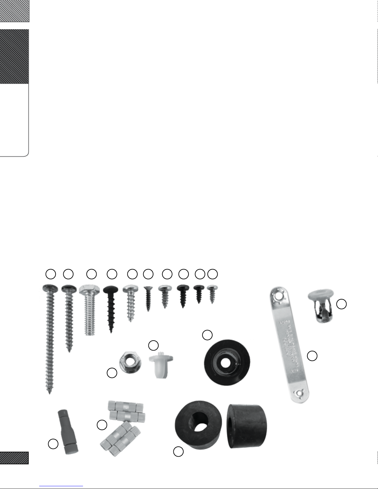
V. SOUNDSTAGE HARDWARE
9. Midrange Mounting Adapter (Pair)
10. Midwoofer Mounting Adapter (Pair)
11. #8 x 1/2” Midwoofer Mounting Screws (12)
12. #6 x 3/8” Midrange Mounting Screws (12)
13. Integral Audio Logo Badge (Pair)
VI. AMPLIFIER INSTALLATION & WIRING
14. Amplfier Power Wiring Harness (complete)
15. Threadlock Wire Splice Connectors (4) [HIFI/HK ONLY]
16. Threadlock Wire Tap (1)
17. Cable Ties (10)
18. 3M Electrical Tape
VII. AMPLIFIER MOUNTING (REAR AMP MOUNT)
19. Amplifier Mounting Bracket
20. M6 Flange Nut
21. Screw Grommet
22. #8 x ½” Truss Head Screw (1)
23. #6 x 3/8” Pan Head Screw (4)
VIII. FACTORY A-PILLAR TRIM W/TWEETER MOUNTS
Continued on the next page . . .

WHAT’S IN THE BOX
4
SOUNDSTAGE
I. SOUNDSTAGE SPEAKER PACKAGE
1. IASS-T 1” Silk Dome Tweeter (Pair)
2. IASS-4 4” Midrange (Pair)
3. IASS-6 6” Midwoofer (Pair)
II. SOUNDSTAGE CROSSOVER NETWORKS WITH
VEHICLE-SPECIFIC TUNING & EQUALIZATION
4. MCSS630MW Mid-Woofer Network (Pair)
5. MCSS630T Tweeter Network (Pair)
III. ARC AUDIO KS MINI AMPLIFIER (2CH W/
SOUNDSTAGE, 4CH W/SOUNDSTAGE + SUBWOOFER)
IV. SIGNAL & SPEAKER WIRING HARNESSES
6. Signal Wiring Harness (MCWH-SIG-R)
7. Mid-Woofer Connection Harness (Pair)
8. Tweeter Pigtail (Pair)
V. SOUNDSTAGE HARDWARE
9. Midrange Mounting Adapter (Pair)
10. Midwoofer Mounting Adapter (Pair)
11. #8 x 1/2” Midwoofer Mounting Screws (12)
12. #6 x 3/8” Midrange Mounting Screws (12)
13. Integral Audio Logo Badge (Pair)
VI. AMPLIFIER INSTALLATION & WIRING
14. Amplfier Power Wiring Harness (complete)
15. Threadlock Wire Splice Connectors (4) [HIFI/HK ONLY]
16. Threadlock Wire Tap (1)
17. Cable Ties (10)
18. 3M Electrical Tape
VII. AMPLIFIER MOUNTING (REAR AMP MOUNT)
19. Amplifier Mounting Bracket
20. M6 Flange Nut
21. Screw Grommet
22. #8 x ½” Truss Head Screw (1)
23. #6 x 3/8” Pan Head Screw (4)
VIII. FACTORY A-PILLAR TRIM W/TWEETER MOUNTS
Continued on the next page . . .
WHAT’S IN THE BOX
5
SUBWOOFER
IX. MC1101S SUBWOOFER ENCLOSURE
X. SB ACOUSTICS 10” SUBWOOFER
XI. SUBWOOFER COVER PANEL
XII. SUBWOOFER HARDWARE
24. Neutrik Speak-On Terminal & Gasket
25. #10 x 2.5” Pan Head Screw (3)
26. #10 x 1.5” Pan Head Screw (6)
27. ¼” x 1” Hex Head Bolt
28. #10 x 1” Black Pan Head Screw (8)
29. #10 x ¾” Pan Head Screw (8)
30. #4 x ½” Black Flathead Screw (2)
31. Threaded Insert (3)
32. Threaded Insert Installation Wrench
33. Cup Washer (6)
34. Rubber Stand-off (9)
35. Subwoofer Mounting Bracket (2)
36. Rosette Thumbscrew (2)
37. Connection Harness (Sub to Neutrik)
XIII. REMOTE LEVEL CONTROL
38. Integral Audio Remote Level Control
39. 3M VHB Double-Sided Mounting Tape (3in)
SeSelect Hardware for Identification:
2725 29
31
231211223028
33
21
20
16
34
32
15
26

TOOLS YOU WILL NEED
6Images Not to Scale
I. PLASTIC PANEL REMOVAL TOOLS
II. TORX BITS:
1. T25
2. T30
3. T40
4. T50
III. DRILL
IV. DRILL BIT:
5. 7/16” [MUST be correct size!]
V. WRENCHES OR SOCKETS:
6. 7/16”
7. 8mm
8. 10mm
9. 10mm Deep [optional}
10. 19mm
VI. ELECTRICIAN’S WIRE FISH
VII. SCISSORS
VIII. UTILITY KNIFE
IX. PLIERS
X. CENTER PUNCH [SUB ONLY]
XI. WIRE STRIPPER [HIFI/HK ONLY]
XII. PICK & HOOK SET [OPTIONAL]
XIII. MAGNETIC PARTS TRAY [OPTIONAL]

A.
PREP VEHICLE
7
1. REMOVE BATTERY COVER
Remove battery cover by turning the locking knob and lifting out
the cover.
2. DISCONNECT BATTERY NEGATIVE TERMINAL
Disconnect battery negative terminal with 10mm deep socket.
3. REMOVE TRUNK FLOOR PANEL
Remove the trunk oor panel.
4. REMOVE TRUNK CENTER BIN (STEP 1)
Locate the center pin of the expansion clip at the forward passen-
ger side corner of the liner.
5. REMOVE TRUNK CENTER BIN (STEP 2)
With a plastic panel removal tool, pry out center pin of the expan-
sion clip. Pry out clip base. Remove bin liner.
A.
PREP VEHICLE
8
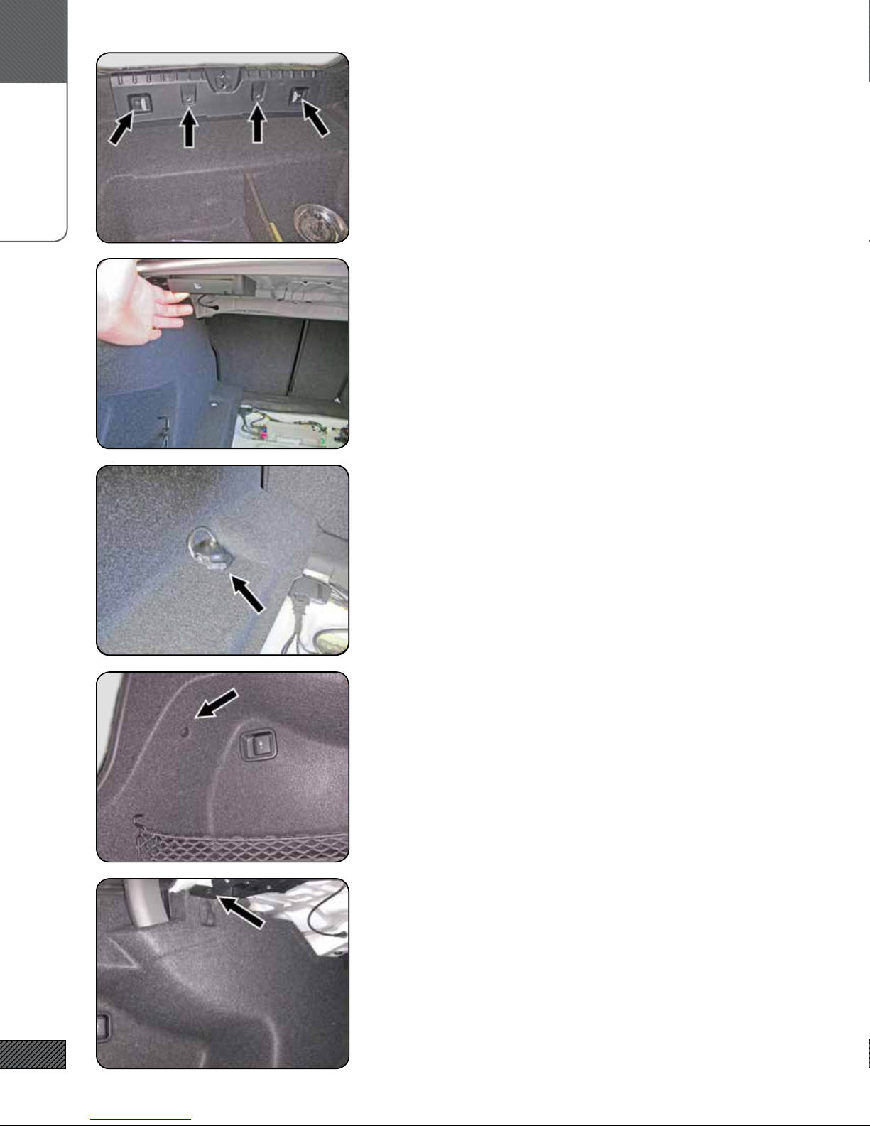
6. REMOVE TRUNK REAR SILL
Remove the trunk rear sill by removing the (4) center pin expan-
sion clips along the inner side. Lift the lower front edge of the sill
forward to clear the D-rings, then give a rm lift up to release the
friction clips holding the upper portion.
7. FOLD DOWN DRIVER SIDE REAR SEAT
Pull the rear seat release located in the trunk, fold down the driv-
er-side rear seat.
8. REMOVE DRIVER-SIDE REAR QUARTER PANEL TRIM (STEP 1)
Locate the luggage D-ring tie down at the forward driver-side of
the trunk. Pry off the black plastic cover. Remove the Torx T-40
screw. Lift out the D-ring assembly.
9. REMOVE DRIVER-SIDE REAR QUARTER PANEL TRIM (STEP 2)
There are (3) center-pin expansion clips that fasten the rear quar-
ter panel trim to the car - locate & remove the one in the upper
part of the rear cubby area.
10. REMOVE DRIVER-SIDE REAR QUARTER PANEL TRIM (STEP 3)
Then locate & remove the one on the side, under the parcel shelf
area. This one is attached to a plastic bracket. Remove the ex-
pansion clip on the upper portion of the bracket, and leave the
bracket attached to the quarter-panel trim.

B.
POWER & GROUND WIRING
9
11. REMOVE DRIVER-SIDE REAR QUARTER PANEL TRIM (STEP 4)
Then locate & remove the one on the forward edge of the panel,
by the rear seat back.
12. REMOVE DRIVER-SIDE REAR QUARTER PANEL TRIM (STEP 5)
Now remove the trim panel. Start at the forward edge. Lift clear/
free the forward edge from behind the trim at the sides of the
rear seat backs and pull the panel out 4-6 inches.
DO NOT COMPLETELY REMOVE YET!
13. REMOVE DRIVER-SIDE REAR QUARTER PANEL TRIM (STEP 6)
Free panel edge along area (1). Then carefully open the split in
the panel at area (2) by pulling the split directly apart (i.e. not
sideways) and free the panel from around the trunk support arm.
DO NOT COMPLETELY REMOVE YET!
14. REMOVE DRIVER-SIDE REAR QUARTER PANEL TRIM (STEP 7)
Disconnect the plug on the back of the 12V power outlet, then
remove the panel from the vehicle.
15. REMOVE PLASTIC COVER
Remove the nut fastening the plastic cover over the amp with a
10mm socket. Remove the cover.

C.
SIGNAL WIRING
10
16. REMOVE THE FACTORY AMPLIFIER & BRACKET
Using a 10mm socket, remove the nut fastening the factory am-
plier bracket to the vehicle. Slide the amplier bracket forward
to clear the mushroom studs and remove the amp and bracket.
17. DISCONNECT FACTORY AMPLIFIER HARNESS
Disconnect the factory wiring harness from the amplier by
pressing in the locking tab (1) and sliding the locking lever (2) to
the left as viewed in the image.
18. REMOVE THE FACTORY AMPLIFIER FROM THE BRACKET
Using an 8mm socket, remove the machine bolt that fastens the
factory amplier to the bracket. Slide the amplier off the brack-
et (you may need to gently use a screwdriver to free the amp from
the bracket).
19. RELOCATE FACTORY AMPLIFIER (STEP 1)
Loosen/free the 12V power outlet wire bundle by sliding the plas-
tic retaining clip off the mounting stud.
20. RELOCATE FACTORY AMPLIFIER (STEP 2)
Loosen/free the sound liner by removing the center pin expansion
clip. Pull the sound liner down and forward to access the area
behind it.

C.
SIGNAL WIRING
11
21. HARDWARE SELECTION
Locate the F30.AMP.RELO.KIT OEM Amplier Relocation Kit, which
contains the OEM_AMP_RELO_BRKT OEM Amp Relocation Bracket
and the hardware packet labeled F30.AMP.RELO.HW F30 OEM
Amplier Relocation Hardware.
22. RELOCATE FACTORY AMPLIFIER (STEP 3)
Slide one of the included clip-on nuts over the hole indicated at
area (1). The threads should be on the inside of the bracket. Slide
the Factory amplier onto the OEM_AMP_RELO bracket. Bend
the tabs on the factory amp at area if needed for a tight t. Se-
cure the amp to the bracket with one of the 10-24 x 1/2” Machine
Screws. Slide the remaining two clip-on nuts over the holes at
area (2). The tapped portion of the clip should be on the same
side as the amp.
23. HARDWARE SELECTION
Locate the Signal Wiring Harness [F30.WH.SIG]. Connector(s):
(1) plugs into the Factory Amplier; (2) plugs into the Factory
Signal Harness; (3) plugs into the USW crossover board; (4) is the
speaker output wiring, connects to ARC amplier speaker output
terminals; (5) the remote turn on lead connects to the ARC am-
plier; (6) RCAs connect to ARC amplier; and (7) and (8) are the
remote volume control and wiring.
24. RELOCATE FACTORY AMPLIFIER (STEP 4)
Pull out the foam sound liner (4). Connect the Signal Wiring
Harness to the factory amplier and lock the connector. Slide the
bracket over the coarse-threaded stud (2). Use the remaining two
#10-24 Truss Head Machine Screws from the hardware kit to secure
the bracket (3). Secure the bottom of the bracket with the thin
sheet metal Flange Nut.
NOTE: if you are installing the subwoofer, do not install the
Flange Nut yet..
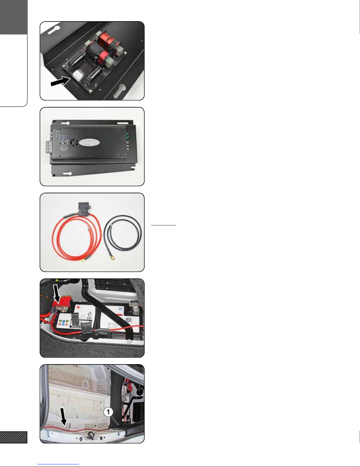
25. HARDWARE SELECTION
Locate the F30.SS.XO-T box and select the F30.XO.USW crossover
(item 1). Locate the F30.AMP.MNT.KIT F30 Amplier Mounting Kit
containing the USW.XO.MS (four #6-32 x 0.25”L Machine Screws
(item 2)), the AMP.MS.R (four #6 x 3/8” Black Sheet Metal Screws
(item 3), and the F30.AMP.BRACKET (4). Locate the ARC amplier.
C.
SIGNAL WIRING
12
26. MOUNT USW CROSSOVER TO AMPLIFIER BRACKET
Mount the F30.XO.USW crossover and to the threaded standoffs
on the underside of the F30.AMP.BRACKET using the four #6-32 x
0.25”L Machine Screws. Make sure the connector on the crossover
is oriented towards the near end of the amplier bracket.
27. MOUNT ARC AMPLIFIER TO BRACKET
Attach the ARC amplier to the F30.AMP.BRACKET using the four
#6 x 3/8” Black Sheet Metal Screws from the AMP.MS.R kit. Make
sure the speaker and RCA terminals are on the same end as the
USW.XO.USW crossover.
Place the completed assembly in the amplier well but do not
mount it to the vehicle yet.
28. HARDWARE SELECTION
Locate the F30.WH.PWR “Power Wiring Harness”.
REMOVE THE FUSE FROM THE FUSE HOLDER, IF PRESENT!
29. ATTACH POSITIVE TERMINAL TO BATTERY
Locate the terminal attachment point shown. Remove the nut
with a 10mm socket and attach the positive wire terminal to the
battery terminal. (You did remember to remove the fuse in the
last step, right?)
30. ROUTE POWER WIRE
Route the wire behind the trim panel (1), along the back edge of
the trunk, and over to the amplier location.

D.
SOUNDSTAGE
13
31. LOCATE COMMON GROUND TERMINAL
Locate the Common Ground point just forward of the amplier
mounting location, above the drivers-side rear wheel well.
32. ATTACH NEGATIVE TERMINAL TO COMMON GROUND
Use a 10mm socket to remove the nut and attach the ground wire
terminal on top of the common ground terminal.
Route the wire to the back of the amplier mounting area.
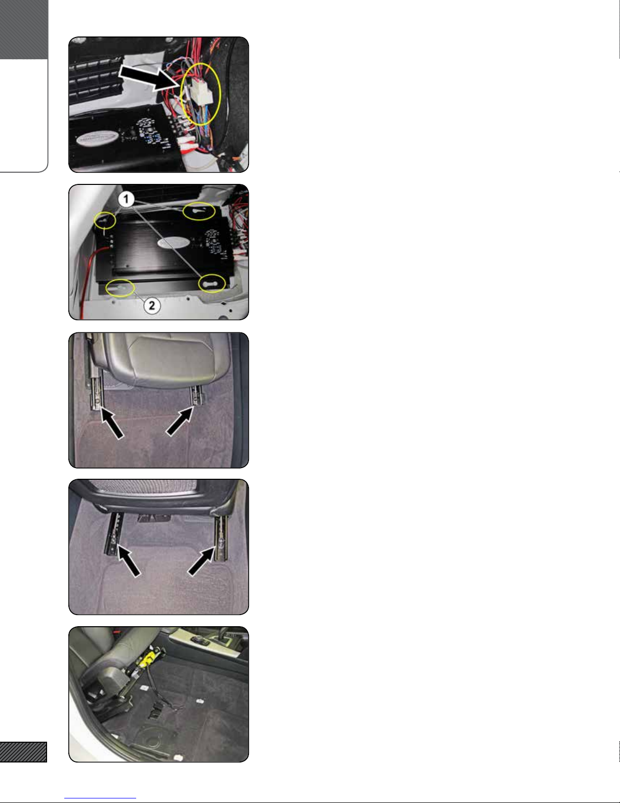
33. AMPLIFIER CONNECTIONS (USW CROSSOVER)
With the amplier in place (but still not mounted) so that you can
route the wires as needed, make the following wiring connec-
tions:
• Connect the 6-pole plug on the Signal Wiring harness (shown)
to the USW Crossover mounted underneath the ARC amplier
34. AMPLIFIER CONNECTIONS (POWER & RCA’S)
• Connect Remote Turn-on wire from the Signal Wiring harness
to the ARC amp Remote On
• Connect Positive & Ground power wires to ARC amp power
terminals
• Connect Front RCAs from Signal Wiring harness to ARC amp
Front RCA inputs
• Connect Subwoofer RCAs from Signal Wiring harness to the
ARC Rear RCA inputs
35. AMPLIFIER CONNECTIONS (SPEAKER OUTPUTS)
• Speaker Outputs from Signal harness to ARC amp. The wires
are labeled, “FL++” is Front Left Positive, “FL--” is Front Left
Negative, etc. There are two wires bundled together for EACH
output connection. Make sure that BOTH wires are securely
connected to the terminal.
D.
SOUNDSTAGE
14
36. AMPLIFIER CONNECTIONS (FACTORY PLUG)
Connect the plug that was originally disconnected from the facto-
ry amplier to the mating connector on the Signal Wiring har-
ness. Take care when connecting that the pins are aligned and do
not get bent. Slide and lock the locking lever.
37. MOUNT AMPLIFIER
Slide the amplier bracket over the mushroom studs (1) and then
rearwards to lock in place. Secure the amplier to the vehicle
with the nut removed earlier (2). NOTE: if you are also installing
the subwoofer, wait to secure the amplier until after you have
connected the subwoofer output wire (in a later step)
38. REMOVE UNDER-SEAT WOOFER (STEP 1)
Slide the passenger-side front seat all the way back Use a Torx
T-50 to remove the two bolts holding the front of the seat brack-
ets.
39. REMOVE UNDER-SEAT WOOFER (STEP 2)
Now slide the seat all the way forward. Remove the two bolts
holding the rear of the seat.
40. REMOVE UNDER-SEAT WOOFER (STEP 3)
Release seat back to the full forward position. You can now lean
the seat all the way back and it will stay in that position, giving
you access to the underseat area. You may have to move the seat
a little forward or backward to get it to stay. You do not need to
disconnect the airbag connecter (we advise against it), but just be
aware that it is there and take care with it.

D.
SOUNDSTAGE
15
41. REMOVE UNDER-SEAT WOOFER (STEP 4)
Remove the four Torx T-20 screws holding the USW cover and
remove the cover.
42. REMOVE UNDER-SEAT WOOFER (STEP 5)
Remove the Door Sill cover trim (1) by rmly pulling up to release
the four clips located underneath (2).
43. REMOVE UNDER-SEAT WOOFER (STEP 6)
Some or all of the plastic clips (1) may still be stuck to the vehicle,
remove them and put them back on the Door Sill cover trim. A
panel removal pry tool (2) works well.
44. REMOVE UNDER-SEAT WOOFER (STEP 7)
Pull up the carpet to access the USW enclosure. Use a 10mm
socket to remove the two nuts (1). Detach the wire bundle clip
attached to the top corner of the USW enclosure (2).
Remove the enclosure by lifting up the inner edge rst, then lift-
ing up and towards the middle of the vehicle. Unplug the wiring/
connector by depressing the locking tab in the connector. Remove
the USW enclosure from the vehicle.
45. REMOVE UNDER-SEAT WOOFER (STEP 8)
Place the USW enclosure on a workbench or other solid work sur-
face. Remove the four Torx T-10 screws (1). Starting at the stron-
gest point (2) carefully pry the woofer from the enclosure.
REPEAT THE PREVIOUS 8 STEPS FOR THE DRIVER SIDE

D.
SOUNDSTAGE
16
46. MOUNT IASS-8S TO ADAPTER PLATE
Locate the two IASS-8S Shallow Woofers and the F30.USW.HW-K IT
Underseat Woofer Hardware Kit. Mount each woofer to an Adapter
using eight of the #10 x 3/4” Black Screws.
47. HARDWARE SELECTION
Locate the two sets of F30.WH.USW Wiring Pigtails, the four #8-32 x
1” Machine Screws, the four #8 Nuts, and the eight #8 Flat Washers.
48. IASS-8S WIRING
Use the #8-32 x 1” Machine Screws to connect the inner and outer
wiring pigtails. The washers should be underneath the ring ter-
minals on both sides.
Connect the positive and negative wires to the speaker terminals
as shown.
49. INSTALL THE IASS-8S WOOFERS IN THE USW ENCLOSURE
Use the four #6 x 1.25” Pan Head Screws to mount the woofer to
the enclosure (these are the longer, thinner screws with a round-
ed head - don’t confuse them with the cover screws which are a
little thicker and shorter and have a at head).
50. RE-INSTALL THE USW ENCLOSURE
Re-install the enclosure in the vehicle. It may take a little wig-
gling to get the open end (the side towards the door sill) to slide
into its slot. Make sure all wiring is run clear. Replace the two
nuts removed previously and tighten with a 10mm socket.
Connect the USW plug to the factory connector. Replace the car-
pet.

D.
SOUNDSTAGAE
17
51. HARDWARE SELECTION
Select the remaining items from the F30.USW.MNT.KIT: the eight
Nylon Spacers and the eight #8 x 1” Flat Head Screws.
Make sure you are selecting the spacers from the correct kit!
52. INSTALL THE USW COVER GRILLE (STEP 1)
Place the spacers over the screw bosses as shown.
(enclosure shown removed for clarity)
53. INSTALL THE USW COVER GRILLE (STEP 2)
The raised “feet” on the cover grille t over the spacers and
should lock into place. Attach the cover with the four #8 x 1” at
head screws. Put the seat back in place, but do not re-bolt it yet!
(enlclosure shown removed for clarity)
REPEAT THE PREVIOUS 8 STEPS FOR THE OTHER SIDE
54. REMOVE THE DRIVERS SIDE DOOR TRIM (STEP 1)
Remove the window control unit by prying up on the front edge
with a plastic panel removal tool. Once the front edge is lifted,
release the clip (see next step image) and lift out.
55. REMOVE THE DRIVERS SIDE DOOR TRIM (STEP 2)
Disconnect the wiring connector by releasing the locking lever.
Remove the window control unit.
D.
SOUNDSTAGE
18
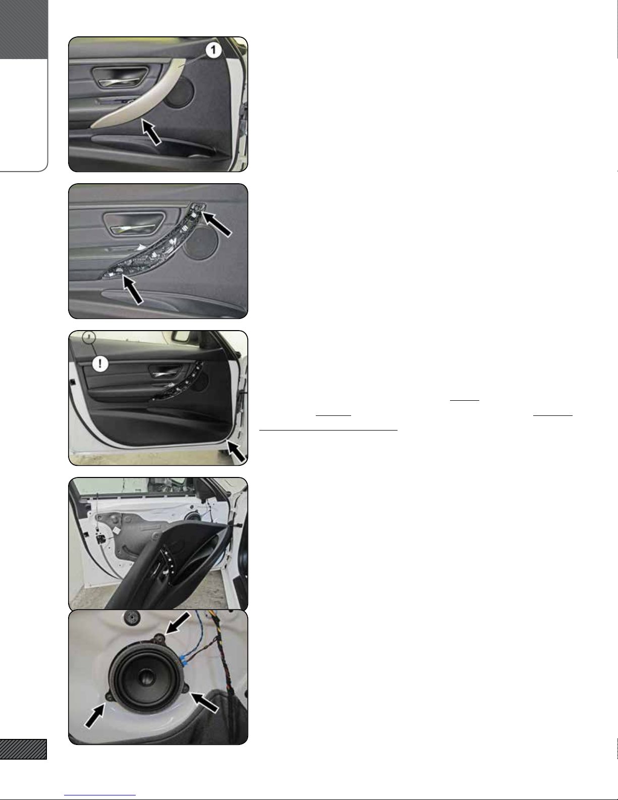
56. REMOVE THE DRIVERS SIDE DOOR TRIM (STEP 3)
Remove the door handle trim cover (1). Look for the small open-
ing indicated by the arrow and start there. Work your way
around the edge and remove the trim.
57. REMOVE THE DRIVERS SIDE DOOR TRIM (STEP 4)
Remove the two Torx T-25 screws shown at the arrows. You will
likely need a nut driver or socket extension to reach them.
58. REMOVE THE DRIVERS SIDE DOOR TRIM (STEP 5)
Remove the Door Trim Panel. Start where the arrow is pointing.
Insert your plastic panel removal tool between the door trim and
the door sheet metal. Pry up until the clips release and you can
get your ngers behind the panel. Pull rmly. Work your way
around the bottom of the door rst., then up to the top. Be care-
ful of the door lock indicator - lift the trim panel up and over the
lock indicator.
59. REMOVE THE DRIVERS SIDE DOOR TRIM (STEP 6)
You do not need to remove the door panel trim completely, but
you can if you want. You can leave it attached and prop up the
bottom, or you can disconnect the door handle release and the
remaining wiring and remove the panel completely.
60. REMOVE THE FACTORY MIDRANGE DRIVER
Remove the three Torx T-20 screws indicated. Unplug and remove
the midrange driver.
Retain the Torx T-20 screws, you will use them to mount the new
midrange.

E.
SUBWOOFER
19
61. HARDWARE SELECTION
Select the two F30.XO.MT Midrange/Tweeter Crossovers from the
F30.SS.XO-T Soundstage Crossovers & Tweeters box.
Select the four Nylon Spacers and the four #8 x 1/2” Large Head
Screws and the 4.5” x 2” Double-sided Foam Tape from the F30.XO-
MT.MNT.KIT (this kit is containted in the F30.MT-XO.HW.KIT)
62. MOUNT MIDRANGE/TWEETER CROSSOVERS (STEP 1)
Orient the Midrange/Tweeter Crossover in the lower rear portion of
the door trim so that the white electrical connector (1) is facing
up and the holes on the forward side of the crossover board (2)
align with the screw bosses on the door (3). Peel the backing
off one side of the 4.5” x 2” Double-sided Foam Tape and afx as
shown - do not cover the holes in the crossover board (2)!
63. MOUNT MIDRANGE/TWEETER CROSSOVERS (STEP 2)
Peel the remaining backing off the 4.5” x 2” Double-sided Foam
Tape and place the Midrange/Tweeter Crossover over the screw
bosses as shown. PRESS & HOLD rmly for 45 seconds.
64. MOUNT MIDRANGE/TWEETER CROSSOVERS (STEP 3)
Slide a Nylon Spacer over each screw boss and secure with a #8
x 1/2” Large Head Screws. Carefully tighten the screws - do not
overtighten!
65. HARDWARE SELECTION
Select the F30.WH.MT-XO Midrange-Tweeter Wiring Harness from
the F30.MT-XO.HW.KIT.
E.
SUBWOOFER
20
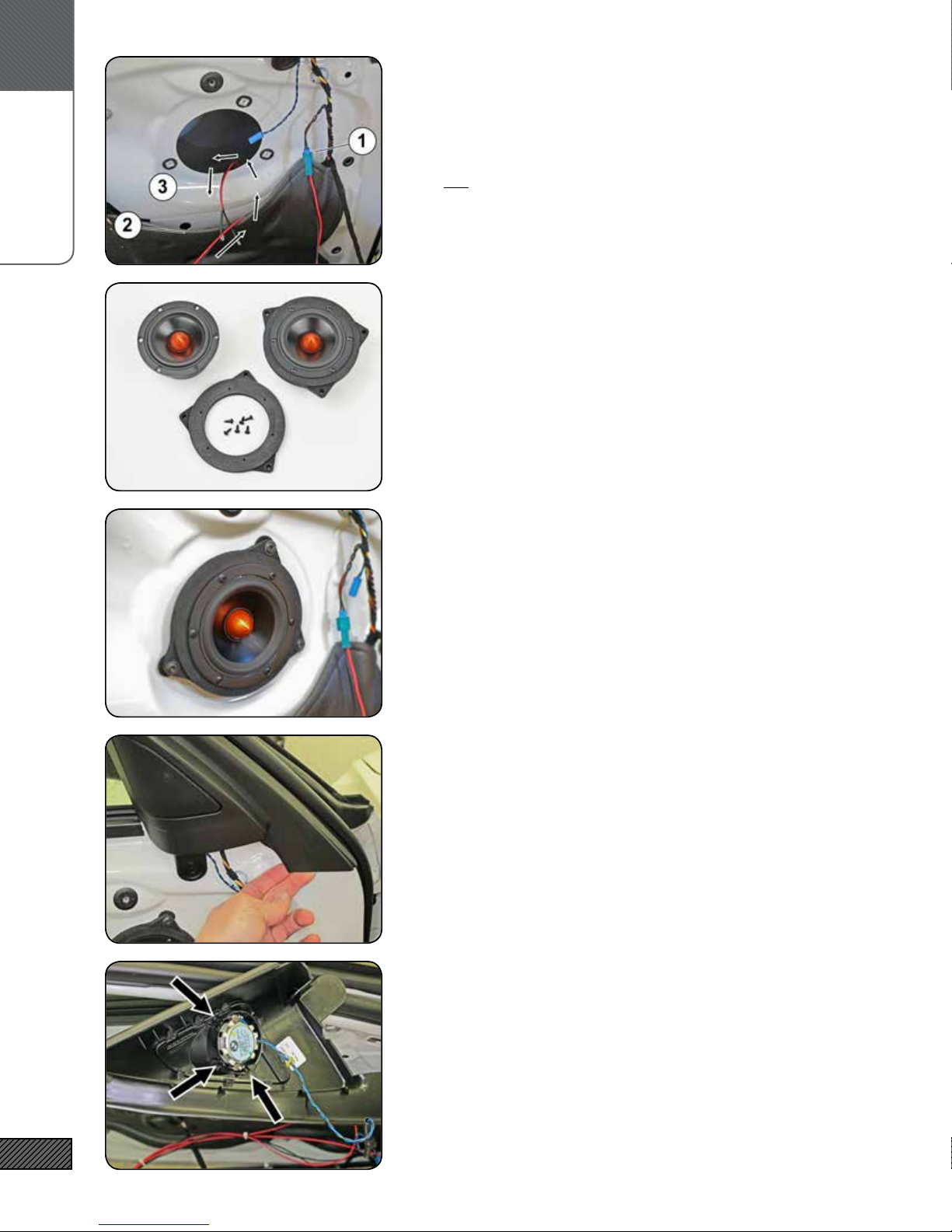
66. CONNECT & ROUTE MID-TWEET HARNESS
Connect the 6-pole plug of the Midrange-Tweeter Wiring Harness to
the mating plug on the crossover.
Connect the plug on the harness (1) to the mating plug on the ve-
hicle (not the tweeter!). Carefully pull open a section of the foam
door liner (2) and route the midrange branch of the harness into
the door and out the midrange speaker cutout.
67. MOUNT IASS-4 TO ADAPTER
Locate the F30.MID.ADAPTER and IASS-4-MS screws in the F30.
MT-XO.HW.KIT. Mount the IASS-4 midrange to the adapter using
the #6 x 3/8” Pan Head Screws.
68. MOUNT IASS-4 TO DOOR
Connect the wiring to the midrange terminals. Using the three
Torx T-20 screws removed earlier, mount the midrange to the
door.
Pull the slack from the midrange wires (just until snug), then
press/re-seal the foam door liner.
69. LOOSEN UPPER DOOR TRIM
Loosen the “mirror sail” portion of the upper door trim. Pull out
on the trim at the bottom of the mirror sail to release the forward
edge, then out and around to release the rear edge (by the win-
dow). You do not need to remove the trim completely, just loosen
enough to gain access to the tweeter behind.
70. REMOVE FACTORY TWEETER
Remove the foam insert. Remove the factory tweeter by releasing
the three plastic catches indicated by the arrows.
This manual suits for next models
1
Table of contents
Other Integral Audio Car Stereo System manuals


